RU2139129C1 - Gas cleaning reactor - Google Patents
Gas cleaning reactor Download PDFInfo
- Publication number
- RU2139129C1 RU2139129C1 RU98107976A RU98107976A RU2139129C1 RU 2139129 C1 RU2139129 C1 RU 2139129C1 RU 98107976 A RU98107976 A RU 98107976A RU 98107976 A RU98107976 A RU 98107976A RU 2139129 C1 RU2139129 C1 RU 2139129C1
- Authority
- RU
- Russia
- Prior art keywords
- gas
- shelves
- layer
- thickness
- row
- Prior art date
Links
- 238000004140 cleaning Methods 0.000 title claims abstract description 14
- 239000003054 catalyst Substances 0.000 claims abstract description 17
- 239000000945 filler Substances 0.000 claims abstract description 13
- 239000000126 substance Substances 0.000 claims abstract description 10
- 230000001154 acute effect Effects 0.000 claims abstract description 4
- 238000000746 purification Methods 0.000 claims description 10
- 238000010276 construction Methods 0.000 abstract 1
- 230000000694 effects Effects 0.000 abstract 1
- 238000000034 method Methods 0.000 abstract 1
- 231100000331 toxic Toxicity 0.000 abstract 1
- 231100000167 toxic agent Toxicity 0.000 abstract 1
- 230000002588 toxic effect Effects 0.000 abstract 1
- 239000003440 toxic substance Substances 0.000 abstract 1
- 239000007789 gas Substances 0.000 description 30
- 239000002657 fibrous material Substances 0.000 description 3
- 238000002485 combustion reaction Methods 0.000 description 2
- 238000010586 diagram Methods 0.000 description 2
- 238000010438 heat treatment Methods 0.000 description 2
- 238000005272 metallurgy Methods 0.000 description 2
- 238000006386 neutralization reaction Methods 0.000 description 2
- TXVHTIQJNYSSKO-UHFFFAOYSA-N benzo[e]pyrene Chemical class C1=CC=C2C3=CC=CC=C3C3=CC=CC4=CC=C1C2=C34 TXVHTIQJNYSSKO-UHFFFAOYSA-N 0.000 description 1
- 238000006243 chemical reaction Methods 0.000 description 1
- 239000000835 fiber Substances 0.000 description 1
- 239000000446 fuel Substances 0.000 description 1
- 239000012535 impurity Substances 0.000 description 1
- 238000009434 installation Methods 0.000 description 1
- 238000004519 manufacturing process Methods 0.000 description 1
- 238000009856 non-ferrous metallurgy Methods 0.000 description 1
- 239000002245 particle Substances 0.000 description 1
- 150000002989 phenols Chemical class 0.000 description 1
- 125000005575 polycyclic aromatic hydrocarbon group Chemical group 0.000 description 1
- 239000012261 resinous substance Substances 0.000 description 1
- 229910001220 stainless steel Inorganic materials 0.000 description 1
- 239000010935 stainless steel Substances 0.000 description 1
Images
Landscapes
- Exhaust Gas Treatment By Means Of Catalyst (AREA)
Abstract
Description
Изобретение относится к устройствам для очистки выбросов, содержащих вредные вещества, такие как смолистые вещества, полициклические ароматические углеводороды, бензопирены, фенолы и т.д., в частности к газоочистным реакторам и может быть использовано в различных областях промышленности, связанных с необходимостью обезвреживания выбросов, имеющих в своем составе вредные вещества. The invention relates to a device for cleaning emissions containing harmful substances, such as resinous substances, polycyclic aromatic hydrocarbons, benzopyrenes, phenols, etc., in particular to gas cleaning reactors and can be used in various industries related to the need to neutralize emissions, containing harmful substances.
Известен волокнистый фильтр в виде полок с волокнистым материалом, соединенных друг с другом зигзагообразно (С.Б. Старк Пылеулавливание и очистка газов в металлургии. М.: Металлургия, 1977, с.49). Known fiber filter in the form of shelves with fibrous material, connected to each other in a zigzag fashion (SB Stark Dust collection and purification of gases in metallurgy. M: Metallurgy, 1977, p. 49).
Недостатком известного фильтра является его низкая эффективность за счет того, что газы одноразово проходят через фильтрующий слой с низкой удельной поверхностью. A disadvantage of the known filter is its low efficiency due to the fact that the gases pass through the filter layer with a low specific surface area once.
Известно также устройство, выбранное в качестве прототипа, в виде реактора для обезвреживания газов - термокаталитического реактора, содержащего теплоизолированный корпус с камерами загрязненного и очищенного газов, между которыми размещены кассеты с входными и выходными полостями, чередующимися по высоте кассеты, причем каждая из кассет представляет собой рамку из нержавеющей стали, покрытую нержавеющей сеткой, на которой выложен фильтрующий слой из муллитокремнеземистого волокнистого материала (ж. Цветная металлургия, N 9, 1990, с. 29-30). Also known is a device selected as a prototype, in the form of a reactor for gas neutralization - a thermocatalytic reactor containing a thermally insulated casing with contaminated and purified gas chambers, between which cassettes are placed with inlet and outlet cavities alternating in height of the cassette, each of the cassettes being a stainless steel frame coated with a stainless mesh on which a filter layer of mullite-siliceous fibrous material is laid out (J. Non-ferrous metallurgy,
Недостатком прототипа является низкий коэффициент использования полезного объема реактора, что ведет либо к недостаточной очистке газов, либо к необходимости увеличения габаритных размеров реактора для увеличения поверхности контактирования. The disadvantage of the prototype is the low utilization of the useful volume of the reactor, which leads either to insufficient purification of gases, or to the need to increase the overall dimensions of the reactor to increase the contact surface.
3адачей, стоящей перед изобретением, является повышение степени очистки газов за счет увеличения площади контактирования газов с катализатором и/или активным наполнителем и как следствие, увеличение производительности реактора при его прежних габаритах. The task facing the invention is to increase the degree of gas purification by increasing the area of contact of the gases with the catalyst and / or active filler and, as a result, increasing the productivity of the reactor with its previous dimensions.
Предложен газоочистной реактор для очистки выбросов, содержащих вредные вещества, включающий теплоизолированный корпус с камерами загрязненного и очищенного газа, между которыми размещены кассеты с входными и выходными полостями, чередующимися по высоте кассеты, новым в котором является то, что кассеты выполнены в виде рядов перфорированных полок с расположенным на них катализатором и/или активным наполнителем, а дополнительно к ним установлен второй ряд полок, пересекающий первый под острым углом и образующий за счет этого замкнутые объемы. A gas cleaning reactor is proposed for cleaning emissions containing harmful substances, including a thermally insulated casing with contaminated and purified gas chambers, between which cassettes are placed with inlet and outlet cavities alternating in height of the cassette, which is new in that the cassettes are made in the form of rows of perforated shelves with a catalyst and / or active filler located on them, and in addition to them, a second row of shelves is installed, crossing the first at an acute angle and thereby forming closed volumes.
Новым является также то, что полки в каждом ряду установлены параллельно. Also new is the fact that the shelves in each row are installed in parallel.
Кроме того, новым является также то, что после пересечения полок по ходу движения газа определяют и устанавливают толщину слоя катализатора и/или наполнителя (активного) согласно формуле:
Bi = Bi-1 • (1+P),
где Bi - определяемая толщина слоя, мм;
Bi-1 - толщина предыдущего слоя, мм;
P = (Ci - Ci+1)/Ci - степень очистки газа с помощью слоя определяемой толщины;
Ci и Ci+1 - концентрация вредных веществ в газе перед и после определяемого слоя, мг/м3.In addition, it is also new that after crossing the shelves in the direction of gas movement, the thickness of the catalyst layer and / or filler (active) is determined and set according to the formula:
B i = B i-1 • (1 + P),
where B i is the determined layer thickness, mm;
B i-1 - the thickness of the previous layer, mm;
P = (C i - C i + 1 ) / C i is the degree of gas purification using a layer of determined thickness;
C i and C i + 1 - concentration of harmful substances in the gas before and after the determined layer, mg / m 3 .
Испытания предлагаемого устройства показали, что степень очистки газов, прошедших через него, резко возрастает при тех же, что и в прототипе, габаритах устройства, что объясняется увеличением полезной площадью контактирования за счет установки дополнительно одного или нескольких параллельных рядов перфорированных полок с катализатором и/или активным наполнителем. При пересечении под углом в 30o площадь контактирования возрастает в 2,1 раза даже с одним дополнительным рядом полок, а под углом в 60o она возрастает в 2,3 раза. Обезвреживание газов происходит в 2 или более этапов при попадании газов в замкнутые объемы, выполненные из перфорированных полок. Газы, проходя через первый слой катализатора и/или наполнителя, частично очищаются, затем вынуждены повторно проходить через слой катализатора, но уже большей толщины и т.д. вплоть до выхода из кассеты в камеру чистого воздуха.Tests of the proposed device showed that the degree of purification of gases passing through it increases sharply with the same dimensions of the device as in the prototype, which is explained by an increase in the useful contact area due to the installation of one or more parallel rows of perforated shelves with a catalyst and / or active filler. When crossing at an angle of 30 o contact area increases by 2.1 times even with one additional row of shelves, and at an angle of 60 o it increases by 2.3 times. The neutralization of gases occurs in 2 or more stages when gases enter the confined spaces made of perforated shelves. Gases passing through the first catalyst and / or filler layer are partially purified, then forced to re-pass through the catalyst layer, but of a larger thickness, etc. until you exit the cassette into the clean air chamber.
При проведении поиска по патентной и научно-технической информации не было обнаружено решений, содержащих совокупность предлагаемых признаков, что позволяет сделать вывод о соответствии критериям "новизна" и "существенные отличия". When conducting a search on patent and scientific and technical information, no solutions were found containing the totality of the proposed features, which allows us to conclude that the criteria of "novelty" and "significant differences" are met.
На фиг. 1 приведена схема газоочистного реактора для очистки выбросов, содержащих вредные вещества. In FIG. 1 is a diagram of a gas purification reactor for cleaning emissions containing harmful substances.
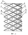
На фиг. 2 приведена схема одного из вариантов расположения полок в кассетах. In FIG. 2 shows a diagram of one of the options for the location of shelves in cassettes.
Предлагается, согласно изобретению, газоочистной реактор для очистки выбросов, содержащих вредные вещества, включающий теплоизолированный корпус 1 с камерами загрязненного 2 и очищенного газа 3, между которыми размещены кассеты 4 с входными 5 и выходными 6 полостями, чередующимися по высоте кассеты 4. Кассеты 4 выполнены в виде рядов перфорированных полок 7 с расположенным на них катализатором 8 и/или активным наполнителем 8 в виде формованных частиц, грубодисперсного или волокнистого материала. Дополнительно к полкам 7 установлен второй ряд полок 9, пересекающий первый по линии пересечения 10 под острым углом α и образующий за счет этого замкнутые объемы 11. Полки 7 и полки 9 расположены в соответствующих рядах параллельно сами себе. Толщину слоя катализатора 8 и/или активного наполнителя 8 после пересечения 10 определяют и устанавливают согласно формуле: Bi = Bi-1 • (1+P) (значения элементов формулы см.выше). В камере 2 загрязненного газа могут быть установлены топливосжигающие устройства 12 или электронагреватели 12 для сжигания вредных примесей и создания температуры, необходимой для дожигания с помощью катализатора 8 и/или активного наполнителя 8. Входной 13 и выходной 14 патрубки располагают в вертикальных или горизонтальных стенках корпуса 1.It is proposed, according to the invention, a gas purification reactor for cleaning emissions containing harmful substances, including a thermally insulated housing 1 with chambers of contaminated 2 and purified gas 3, between which there are
Устройство работает следующим образом. The device operates as follows.
Разогрев реактора и катализатора 8 и/или активного наполнителя 8 происходит за счет тепла очищаемых выбросов. Если этого тепла не достаточно, в качестве дополнительного источника может служить горение топлива в топливосжигающих устройствах 12 или же подогрев за счет электронагревателей 12 до температуры начала реакции между катализатором 8 и очищаемым газом. Загрязненные газы через патрубок 13 подают в камеру 2 загрязненного газа, где происходит частичное сгорание вредных веществ при помощи устройств 12, после чего газ попадает во входные 5 полости кассеты 4, доходит до места пересечения 10 со вторым рядом полок 9 проходит в замкнутые объемы 11, просачивается через полки 7 и 9 с расположенным на них катализатором 8 и через выходные полости 6 попадают, очистившись в камеру 3 очищенного газа. Проходя путь от камеры грязного 2 до камеры очищенного 3 газа по сложной траектории, образованной пересечением полок 7 и 9 с катализатором 8 газ, очистившись выходит в патрубок 14. The heating of the reactor and
Предлагаемый газоочистной реактор позволяет довести очистку газов до 99,9%, не меняя при этом габаритных размеров. Его изготовление несложно, технологично, устройство работает надежно в течение всего срока службы. The proposed gas purification reactor allows to bring the purification of gases to 99.9%, without changing the overall dimensions. Its manufacture is simple, technologically advanced, the device works reliably throughout the entire service life.
Claims (3)
Bi = Bi - 1 • (1 + P),
где Bi - определяемая толщина слоя, мм;
Bi - 1 - толщина предыдущего слоя, мм;
P = (Ci - Ci + 1)/Ci - степень очистки газа с помощью слоя определяемой толщины;
Ci и Ci + 1 - концентрация вредных веществ в газе перед и после определяемого слоя, мг/м3.3. The gas cleaning reactor according to claim 1, characterized in that after crossing the shelves along the gas, the thickness of the catalyst layer and / or active filler is determined and set according to the formula
B i = B i - 1 • (1 + P),
where B i is the determined layer thickness, mm;
B i - 1 - the thickness of the previous layer, mm;
P = (C i - C i + 1 ) / C i is the degree of gas purification using a layer of determined thickness;
C i and C i + 1 - concentration of harmful substances in the gas before and after the determined layer, mg / m 3 .
Priority Applications (1)
| Application Number | Priority Date | Filing Date | Title |
|---|---|---|---|
| RU98107976A RU2139129C1 (en) | 1998-04-21 | 1998-04-21 | Gas cleaning reactor |
Applications Claiming Priority (1)
| Application Number | Priority Date | Filing Date | Title |
|---|---|---|---|
| RU98107976A RU2139129C1 (en) | 1998-04-21 | 1998-04-21 | Gas cleaning reactor |
Publications (1)
| Publication Number | Publication Date |
|---|---|
| RU2139129C1 true RU2139129C1 (en) | 1999-10-10 |
Family
ID=20205303
Family Applications (1)
| Application Number | Title | Priority Date | Filing Date |
|---|---|---|---|
| RU98107976A RU2139129C1 (en) | 1998-04-21 | 1998-04-21 | Gas cleaning reactor |
Country Status (1)
| Country | Link |
|---|---|
| RU (1) | RU2139129C1 (en) |
Cited By (1)
| Publication number | Priority date | Publication date | Assignee | Title |
|---|---|---|---|---|
| RU2297273C2 (en) * | 2004-07-26 | 2007-04-20 | Александр Данилович Соколов | Device for cleaning waste gases containing organic agents (versions) |
Citations (7)
| Publication number | Priority date | Publication date | Assignee | Title |
|---|---|---|---|---|
| GB2047562A (en) * | 1979-04-20 | 1980-12-03 | Gen Motors Corp | Catalytic converters for internal combustion engine exhaust gases |
| US4278639A (en) * | 1979-03-19 | 1981-07-14 | Toyo Kogyo Co., Ltd. | Catalytic converter for purifying gases |
| DE3927895C1 (en) * | 1989-08-24 | 1990-09-13 | Leistritz Ag, 8500 Nuernberg, De | |
| SU1620118A1 (en) * | 1989-01-09 | 1991-01-15 | Центральное Проектно-Конструкторско-Технологическое Бюро "Электротехмонтаж" | Adsorber |
| DE4024015A1 (en) * | 1990-07-28 | 1992-02-06 | Boysen Friedrich Gmbh Co Kg | DEVICE FOR CATALYTIC CLEANING OR DISASSEMBLY OF HOT EXHAUST GAS |
| DE4039952A1 (en) * | 1990-12-14 | 1992-06-17 | Hasso Von Bluecher | Zeolite adsorber for exhaust catalytic converters - for emissions redn. during cold start=up period of diesel engines |
| RU2047328C1 (en) * | 1992-07-15 | 1995-11-10 | Товарищество с ограниченной ответственностью Фирма "Полимер" | Device for adsorption and desorption |
-
1998
- 1998-04-21 RU RU98107976A patent/RU2139129C1/en active
Patent Citations (7)
| Publication number | Priority date | Publication date | Assignee | Title |
|---|---|---|---|---|
| US4278639A (en) * | 1979-03-19 | 1981-07-14 | Toyo Kogyo Co., Ltd. | Catalytic converter for purifying gases |
| GB2047562A (en) * | 1979-04-20 | 1980-12-03 | Gen Motors Corp | Catalytic converters for internal combustion engine exhaust gases |
| SU1620118A1 (en) * | 1989-01-09 | 1991-01-15 | Центральное Проектно-Конструкторско-Технологическое Бюро "Электротехмонтаж" | Adsorber |
| DE3927895C1 (en) * | 1989-08-24 | 1990-09-13 | Leistritz Ag, 8500 Nuernberg, De | |
| DE4024015A1 (en) * | 1990-07-28 | 1992-02-06 | Boysen Friedrich Gmbh Co Kg | DEVICE FOR CATALYTIC CLEANING OR DISASSEMBLY OF HOT EXHAUST GAS |
| DE4039952A1 (en) * | 1990-12-14 | 1992-06-17 | Hasso Von Bluecher | Zeolite adsorber for exhaust catalytic converters - for emissions redn. during cold start=up period of diesel engines |
| RU2047328C1 (en) * | 1992-07-15 | 1995-11-10 | Товарищество с ограниченной ответственностью Фирма "Полимер" | Device for adsorption and desorption |
Non-Patent Citations (2)
| Title |
|---|
| В.М.Матерухин, В.П.Белов, Н.Т.Важенина, В.В.Косинов Очистка газов камеры обжига графитовых изделий. - Ж. "Цветная металлургия", 1990, N 9, с.29 - 30. * |
| С.Б.Старк Волокнистые фильтры. Пылеулавливание и очистка газов в металлургии. - М.: Металлургия, 1977, с.49. * |
Cited By (1)
| Publication number | Priority date | Publication date | Assignee | Title |
|---|---|---|---|---|
| RU2297273C2 (en) * | 2004-07-26 | 2007-04-20 | Александр Данилович Соколов | Device for cleaning waste gases containing organic agents (versions) |
Similar Documents
| Publication | Publication Date | Title |
|---|---|---|
| US4871515A (en) | Electrostatic filter | |
| US5935525A (en) | Air treatment method and apparatus for reduction of V.O.C.s, NOx, and CO in an air stream | |
| US5492677A (en) | Contaminated air purifying apparatus | |
| US7070744B2 (en) | Purification system of exhaust gases of an internal combustion engine | |
| US3476524A (en) | Apparatus and method for treating gaseous products of combustion | |
| JPH09217618A (en) | Exhaust emission control device | |
| CN103900132A (en) | Compound type cooking fume purifier with coupling function | |
| JPH0714459B2 (en) | Exhaust gas treatment method | |
| KR20190000735U (en) | Evacuator system conducting atmosphere purification function | |
| RU2139129C1 (en) | Gas cleaning reactor | |
| CN108844113B (en) | Fluidized bed type oil fume treatment equipment and application thereof | |
| US20060204408A1 (en) | Furification system of exhaust gases of an internal combustion engine | |
| JP2003222016A (en) | Dust removal equipment | |
| JP2591260B2 (en) | Engine exhaust purification device | |
| KR102588533B1 (en) | Apparatus for treating waste gas of electronics industry | |
| RU2171430C1 (en) | Device for thermocatalytic cleaning of ventilation effluents from painting chambers | |
| KR102428957B1 (en) | Air purifying apparatus | |
| RU2297273C2 (en) | Device for cleaning waste gases containing organic agents (versions) | |
| GB2303693A (en) | Gas treatment with liquid spray | |
| RU2130566C1 (en) | Reactor for cleaning off-gases | |
| KR19990011217A (en) | Incinerator Soot Purifier | |
| KR200291649Y1 (en) | Condensing and heat system | |
| RU16462U1 (en) | DEVICE FOR DESTROYING HARMFUL COMPONENTS OF SMOKE GAS | |
| JP2002028444A (en) | Activated carbon packed tower | |
| CN114251846B (en) | Coal-fired hot-air furnace |