RU2137723C1 - Furnace and method of bending glass - Google Patents
Furnace and method of bending glass Download PDFInfo
- Publication number
- RU2137723C1 RU2137723C1 RU94044525A RU94044525A RU2137723C1 RU 2137723 C1 RU2137723 C1 RU 2137723C1 RU 94044525 A RU94044525 A RU 94044525A RU 94044525 A RU94044525 A RU 94044525A RU 2137723 C1 RU2137723 C1 RU 2137723C1
- Authority
- RU
- Russia
- Prior art keywords
- furnace
- sheet
- screen
- heating
- bending
- Prior art date
Links
Images


Classifications
-
- C—CHEMISTRY; METALLURGY
- C03—GLASS; MINERAL OR SLAG WOOL
- C03B—MANUFACTURE, SHAPING, OR SUPPLEMENTARY PROCESSES
- C03B5/00—Melting in furnaces; Furnaces so far as specially adapted for glass manufacture
-
- C—CHEMISTRY; METALLURGY
- C03—GLASS; MINERAL OR SLAG WOOL
- C03B—MANUFACTURE, SHAPING, OR SUPPLEMENTARY PROCESSES
- C03B23/00—Re-forming shaped glass
- C03B23/02—Re-forming glass sheets
- C03B23/023—Re-forming glass sheets by bending
- C03B23/025—Re-forming glass sheets by bending by gravity
- C03B23/0258—Gravity bending involving applying local or additional heating, cooling or insulating means
-
- C—CHEMISTRY; METALLURGY
- C03—GLASS; MINERAL OR SLAG WOOL
- C03B—MANUFACTURE, SHAPING, OR SUPPLEMENTARY PROCESSES
- C03B23/00—Re-forming shaped glass
- C03B23/02—Re-forming glass sheets
- C03B23/023—Re-forming glass sheets by bending
- C03B23/0235—Re-forming glass sheets by bending involving applying local or additional heating, cooling or insulating means
-
- C—CHEMISTRY; METALLURGY
- C03—GLASS; MINERAL OR SLAG WOOL
- C03B—MANUFACTURE, SHAPING, OR SUPPLEMENTARY PROCESSES
- C03B29/00—Reheating glass products for softening or fusing their surfaces; Fire-polishing; Fusing of margins
- C03B29/04—Reheating glass products for softening or fusing their surfaces; Fire-polishing; Fusing of margins in a continuous way
- C03B29/06—Reheating glass products for softening or fusing their surfaces; Fire-polishing; Fusing of margins in a continuous way with horizontal displacement of the products
- C03B29/08—Glass sheets
Abstract
Description
Изобретение касается печи для изгибания стекла, т.е. печи, предназначенной для нагрева подлежащих изгибанию стеклянных листов, для изгибания стеклянных листов до сложной конфигурации, при котором требуется точный контроль профиля распределения температур по каждому листу стекла. Изобретение также касается способа изгибания стеклянных листов с использованием такой печи. The invention relates to a glass bending furnace, i.e. a furnace designed to heat glass sheets to be bent to bend glass sheets to a complex configuration, which requires precise control of the temperature distribution profile for each glass sheet. The invention also relates to a method for bending glass sheets using such a furnace.
На конфигурацию, в которую формуется стеклянный лист при любом изгибающем процессе, сильно влияет температура листа вследствие быстрых изменений вязкости стекла с изменением температуры. Кроме того, точно так же существенное влияние оказывают перепады температур внутри стеклянного листа. Поэтому весьма желательно точно контролировать профиль распределения температур по листу, чтобы успешно создавать конкретные формы, а также гарантировать воспроизводимость при массовом производстве. The configuration into which the glass sheet is molded in any bending process is greatly affected by the temperature of the sheet due to rapid changes in the viscosity of the glass with temperature. In addition, temperature differences inside the glass sheet also have a significant effect. Therefore, it is highly desirable to precisely control the temperature distribution profile over the sheet in order to successfully create specific forms, as well as guarantee reproducibility in mass production.
Из патента EP 504 117 известно управление профилем распределения температур по листу стекла в сочетании с этапом отжига, чтобы в дифференциальной форме закалить лист. From the patent EP 504 117 it is known to control the temperature distribution profile over a glass sheet in combination with an annealing step in order to temper the sheet in a differential form.
Простой способ воздействия на профиль распределения температур в подлежащем изгибу стеклянном листе заключается в размещении экранов на те части стеклянного листа, которые следует нагревать в меньшей степени, затеняя тем самым эти части, т.е. загораживая их от тепла. При эксплуатации эти экраны становятся горячими и сами становятся вторичными излучателями тепла, снижая их эффективность. В патенте США N 4.687.501, выданном фирме "PPG Индастриез Инк", сделана попытка уменьшить эту проблему посредством обеспечения изгибания под действием силы тяжести с помощью вторичных экранов для затенения стекла от горячих первичных экранов. Это неизбежно делает конструкцию до некоторой степени громоздкой, т.к. такие экраны будут загромождать оборудование автоматического манипулирования стеклом, обычно используемое на современных заводах для перемещения стеклянных листов от одного этапа процесса к следующему. A simple way of influencing the temperature distribution profile in the glass sheet to be bent is to place screens on those parts of the glass sheet that should be heated to a lesser extent, thereby obscuring these parts, i.e. blocking them from heat. During operation, these screens become hot and themselves become secondary heat emitters, reducing their effectiveness. US Pat. No. 4,687,501, issued to PPG Industries Inc., attempts to reduce this problem by providing bending due to gravity using secondary screens to shade glass from hot primary screens. This inevitably makes the construction somewhat cumbersome, as such screens will clutter up the automatic glass handling equipment commonly used in modern plants to move glass sheets from one process step to the next.
Такие экраны обычно прикрепляют к форме или другой опоре, которая несет стеклянный лист, так что экраны движутся со стеклянным листом через печь или даже через всю систему изгибания. Однако обычная система изгибания стекла такого типа, в которой стекло нагревается, когда оно находится на форме, содержит много форм, каждая из которых должна быть снабжена экранами, так что в общем требуется большое количество экранов, и любая регулировка экранов, требуемая на одной форме, может точно так же потребоваться на каждой другой форме. Поскольку эти экраны можно регулировать только когда форма находится вне печи, созданную картину затенения нельзя менять во время прохождения листа стекла через различные нагревательные участки в печи. Эта негибкость в настоящее время рассматривается как недостаток, так как при производстве все более сложных конфигураций стекла, требуемых современными конструкторами средств передвижения, желательно, чтобы можно было изменять профиль нагревания на разных участках нагрева для различных целей. Например, может появиться желание обеспечить дополнительное нагревание на углах стеклянного листа, но только тогда, когда лист в целом достигнет температуры изгибания. По самой своей природе экраны этого типа пригодны только для снижения степени нагрева, которую получает стеклянный лист, и причем только на относительно небольшой площади. Попыток направлять тепло, блокированное этими экранами на участок листа, на котором требуется увеличение нагрева, не производилось. Such screens are usually attached to a mold or other support that carries a glass sheet, so that the screens move with the glass sheet through the oven or even through the entire bending system. However, a conventional glass bending system of the type in which the glass is heated when it is on the mold contains many shapes, each of which must be provided with screens, so in general a large number of screens are required, and any adjustment of the screens required on one form, may just as well be required on every other form. Since these screens can only be adjusted when the shape is outside the furnace, the created shading pattern cannot be changed while the glass sheet passes through various heating sections in the furnace. This inflexibility is currently regarded as a disadvantage, since in the production of increasingly complex glass configurations required by modern vehicle designers, it is desirable that the heating profile can be changed at different heating sites for various purposes. For example, you may want to provide additional heating at the corners of the glass sheet, but only when the sheet as a whole reaches the bending temperature. By their very nature, screens of this type are only suitable for reducing the degree of heating that the glass sheet receives, and only in a relatively small area. Attempts to direct heat blocked by these screens to a portion of the sheet on which an increase in heating is required were not made.
Кроме того, поскольку обычно экраны также остаются на месте во время прохождения стекла через участки отжига изгибающей системы, экраны осуществляют охлаждение стекла. Это может создавать нежелательные структуры напряжений в стекле и проблемы оптического искажения. In addition, since typically the screens also remain in place during the passage of the glass through the annealing sections of the bending system, the screens cool the glass. This can create unwanted stress patterns in the glass and optical distortion problems.
Известно также использование поглотителей тепла, т.е. тел, помещенных рядом со стеклом, которые абсорбируют тепло от него, управляя профилем распределения температур в стеклянном листе. Однако эффективность поглотителей тепла также снижается, когда они достигают температуры окружающей среды, и поскольку их также обычно прикрепляют к форме или другой опоре стекла, их использование сопровождается также большим количеством недостатков дополнительно к недостаткам экранов. It is also known to use heat absorbers, i.e. bodies placed next to the glass, which absorb heat from it, controlling the temperature distribution profile in the glass sheet. However, the efficiency of heat absorbers also decreases when they reach ambient temperature, and since they are also usually attached to a mold or other glass support, their use is also accompanied by a large number of disadvantages in addition to the disadvantages of screens.
В патенте Великобритании GB 2.201.670A предлагают технику, противоположную использованию поглотителей тепла, а именно использование тела из термоизоляционного материала типа отражателя тепла; раскрыт лабораторный эксперимент, в котором такое тело помещено под участок стеклянного листа, где предпочтительно требуется его нагревать. В производственной печи такие отражатели также должны быть смонтированы на форме (или по крайней мере в ящиках или на тележках, которые несут форму) и, таким образом, они будут подвергаться тем же проблемам, которые описаны выше в отношении экранов и поглотителей тепла. British Patent GB 2.201.670A proposes a technique that is the opposite of using heat absorbers, namely the use of a body of heat-insulating material such as a heat reflector; A laboratory experiment is disclosed in which such a body is placed under a portion of a glass sheet where it is preferably required to be heated. In a production furnace, such reflectors must also be mounted on the mold (or at least in drawers or carts that carry the mold) and thus they will be subject to the same problems that are described above with respect to screens and heat absorbers.
Там, где требуется усиленный подвод тепла к локализованному участку, давно известно приложение дополнительного тепла к этому конкретному участку с помощью вспомогательных нагревателей, известных специалистам в данной области техники под названием "изгибаемые нагреватели". Патент Соединенного Королевства N UK 836.560 является одним из большого количества описаний, в которых описаны такие нагреватели, в этом варианте осуществления нагреватели подвешивают через прорези в кровле печи, но возможны другие формы поддерживания. Если необходимо ограничить участок стеклянного листа, нагреваемого изгибаемым нагревателем, соседние участки стеклянного листа можно затенять от него, как показано на фиг.10 патента EP 336.216 A2. Where an enhanced supply of heat to a localized area is required, it has long been known to apply additional heat to this specific area using auxiliary heaters known to those skilled in the art as “flexible heaters”. United Kingdom Patent No. UK 836.560 is one of a large number of descriptions describing such heaters, in this embodiment, the heaters are suspended through slots in the roof of the furnace, but other forms of support are possible. If it is necessary to limit a portion of a glass sheet heated by a bending heater, adjacent portions of the glass sheet can be shaded from it, as shown in FIG. 10 of EP 336.216 A2.
Хотя такие изгибаемые нагреватели служат полезной цели, они также имеют много недостатков, таких как загромождение пространство в печи выше стеклянных листов и склонность к повреждению и разрегулированности. Их нельзя использовать над серединой листа, где потребуется длинный поддерживающий кронштейн, который сам будет экранировать стекло. Из-за необходимости поддержания изгибаемые нагреватели нельзя делать достаточно большими для перекрытия существенных участков. Попытка уменьшить некоторые проблемы, например, автоматизирование регулировки и введения - изъятия изгибаемых нагревателей серводвигателями, влечет за собой большие расходы и риск ненадежности. Кроме того, они не подходят для создания нелокальных перепадов температур, таких как перепад от центра к кромке, управляемый на всем расстоянии от центра до кромки стеклянного листа. Although such bendable heaters serve a useful purpose, they also have many disadvantages, such as cluttering the space in the oven above the glass sheets and the tendency to damage and out of alignment. They can not be used above the middle of the sheet, where a long support bracket is required, which itself will shield the glass. Because of the need to maintain, bendable heaters cannot be made large enough to cover significant areas. An attempt to reduce some problems, for example, automation of adjustment and introduction - removal of bent heaters by servomotors, entails high costs and the risk of unreliability. In addition, they are not suitable for creating non-local temperature differences, such as a difference from the center to the edge, controlled at the entire distance from the center to the edge of the glass sheet.
Один способ управления профилем распределения температур по всему стеклянному листу заключается в устройстве в печи для изгибания стекла раздельного регулирования нагревателей для отдельных участков либо действительно отдельных нагревательных элементов. Например, в патенте EP 443,948 A1 раскрывается печь, которая в верхней части содержит группу электрических сопротивлений с независимо регулируемой температурой или мощностью в этих группах. Ориентация и расположение таких групп сопротивлений также обеспечивается так, чтобы оптимизировать управление профилем распределения температур в стеклянном листе. В такой печи можно управлять и температурным профилем по всему стеклянному листу. Целью может быть получение по возможности однородной температуры в листе или создание частичного перепада от центра к краю в соответствии с требованиями конкретной формы, которую подлежит создать. One way to control the temperature distribution profile over the entire glass sheet is to provide separate control of the heaters for individual sections or truly separate heating elements in a glass bending furnace. For example, EP 443,948 A1 discloses a furnace, which in the upper part contains a group of electrical resistances with independently controlled temperature or power in these groups. The orientation and arrangement of such resistance groups is also provided so as to optimize the control of the temperature distribution profile in the glass sheet. In such an oven, it is possible to control the temperature profile over the entire glass sheet. The goal may be to obtain as uniform a temperature as possible in the sheet or to create a partial drop from the center to the edge in accordance with the requirements of the particular form to be created.
Однако существуют ограничения по величине создаваемых таким образом перепадов температур. Если к конкретной группе элементов подведена высокая энергия для предпочтительного нагрева части стеклянного листа непосредственно ниже этой группы, смежные части листа также неизбежно будут получать дополнительный нагрев. Управлять этим можно только на некотором удалении путем снижения расстояния от элементов до стеклянного листа. Хотя уменьшение этого расстояния снижает нежелательный нагрев смежных частей стеклянного листа, оно может привести к оптическому искажению стеклянного листа, если расстояние станет слишком маленьким. Следовательно, остается потребность в решении дополнительных технических задач. However, there are limitations on the magnitude of the temperature differences thus created. If high energy is supplied to a particular group of elements to preferentially heat a portion of the glass sheet immediately below that group, adjacent parts of the sheet will also inevitably receive additional heating. This can be controlled only at some distance by reducing the distance from the elements to the glass sheet. Although decreasing this distance reduces undesirable heating of adjacent parts of the glass sheet, it can lead to optical distortion of the glass sheet if the distance becomes too small. Consequently, there remains a need for solving additional technical problems.
В патенте ЕР 443.948. A1 получено следующее управление профилем распределения температур путем обеспечения дополнительных нагревательных элементов в стенках печи. Например, в последнем абзаце описания раскрывается изготовление S-образного листового стекла и необходимость обеспечения явной разницы температур между отдельными частями стеклянного листа. Последнее изречение этого абзаца объясняет, что выгодно нагревать направленную вверх часть S-образного листового стекла с помощью стенных нагревателей, чтобы избежать перегрева средней части листа, но, конечно, обеспечение дополнительных нагревателей в стенках печи влечет за собой дополнительные расходы, может оказаться желательным получить дополнительное управление температурой, требуемое для некоторой продукции, используя нагревательные элементы только в кровле. In patent EP 443.948. A1 obtained the following control of the temperature distribution profile by providing additional heating elements in the walls of the furnace. For example, the last paragraph of the description discloses the manufacture of an S-shaped sheet glass and the need to provide a clear temperature difference between the individual parts of the glass sheet. The last statement of this paragraph explains that it is advantageous to heat the upward portion of the S-shaped sheet glass with wall heaters in order to avoid overheating of the middle part of the sheet, but, of course, providing additional heaters in the furnace walls entails additional costs, it may be desirable to obtain additional temperature control required for some products using heating elements only in the roof.
Легче управлять изгибанием стекла при так называемом "просто" изгибе, т. е. когда оси кривизны оказываются параллельными или только под небольшими углами друг к другу, и обычно так обстояло дело в прошлом. Однако все больше требуется стекло сложной формы, т.е. стекло, имеющее кривизну в двух по существу перпендикулярных направлениях, например, для применения в автомобилях, а это представляет дополнительные трудности. It is easier to control the bending of the glass with the so-called “simple” bending, that is, when the axis of curvature are parallel or only at small angles to each other, and this is usually the case in the past. However, glass of complex shape, i.e. glass having curvature in two essentially perpendicular directions, for example, for use in automobiles, and this presents additional difficulties.
Когда такое стекло делают с помощью процесса изгибания под действием силы тяжести или "провисания", трудность испытывают, например, при получении требуемого поперечного профиля кривизны. Под поперечным профилем кривизны понимают изменение кривизны в направлении, идущем от верхней до нижней части окна, например ветрового окна, если на него смотреть при установленном положении. Такая кривизна создается относительно одной или более по существу горизонтальных осей, простирающихся от одной стороны транспортного средства к другой. Часто требуется размерно круглый поперечный профиль кривизны, но на практике в средней части лобового стекла получается более плоский участок с большей кривизной около верхней и нижней частей. Это может привести к восприятию водителем нежелательного вторичного изобретения. В тех случаях, когда требуется увеличенная степень сложности кривизны и (или) высота ветрового стекла возрастает относительно его ширины, в середине ветрового стекла может появиться обратная поперечная кривизна, так что поперечное сечение оси симметрии начнет походить на перевернутую букву "W". Дополнительно к оптическим проблемам это приводит к плохому коэффициенту полезного действия стеклоочистителя. Чтобы обеспечить удовлетворительное изгибание таких форм, важно достигать более высокие температуры в центральной зоне стеклянного листа с более высокими перепадами температур между центром и дальним краем стеклянного листа, чем было возможно до сих пор. Следовательно, существует необходимость обеспечения способа достижения таких более высоких перепадов между центром и краем. When such glass is made using a bending process under the influence of gravity or "sagging", difficulty is experienced, for example, in obtaining the desired transverse profile of curvature. By the transverse profile of curvature is understood the change in curvature in the direction going from the top to the bottom of the window, for example a wind window, if you look at it when the position is set. Such curvature is created relative to one or more essentially horizontal axes extending from one side of the vehicle to the other. Often a dimensionally circular transverse profile of curvature is required, but in practice a flatter section with a greater curvature near the upper and lower parts is obtained in the middle part of the windshield. This may lead to the driver perceiving an undesirable secondary invention. In cases where an increased degree of complexity of curvature is required and / or the height of the windshield increases relative to its width, an inverse transverse curvature may appear in the middle of the windshield so that the cross section of the axis of symmetry begins to resemble the inverted letter “W”. In addition to optical problems, this leads to poor wiper efficiency. To ensure satisfactory bending of such shapes, it is important to achieve higher temperatures in the central zone of the glass sheet with higher temperature differences between the center and the far edge of the glass sheet than has been possible so far. Therefore, there is a need to provide a way to achieve such higher differences between the center and the edge.
Кроме того, для производства оконного стекла, имеющего асимметричный поперечный профиль кривизны, например S-образной формы, требуется создать по стеклянному листу асимметричный профиль распределения температур. Такая асимметрия может принимать форму смещенной максимальной температуры, т.е. расположенной где-то еще, а не в центре стеклянного листа. Кроме того, или в качестве альтернативы, асимметрии можно добиться в результате разных температур градиентов от точки максимальной температуры до двух дальних краев. In addition, for the production of window glass having an asymmetric transverse profile of curvature, for example an S-shape, it is required to create an asymmetric temperature distribution profile on the glass sheet. Such an asymmetry can take the form of a displaced maximum temperature, i.e. located somewhere else, and not in the center of the glass sheet. In addition, or alternatively, asymmetries can be achieved as a result of different temperature gradients from the point of maximum temperature to two far edges.
При других технологических процессах изгибания, например, при которых используют две формы или матрицы для формования стеклянного листа, желательно также обеспечить возможность более точно управлять профилем распределения температур, сообщаемых стеклянному листу на стадии нагревания, и посредством менее громоздких, более управляемых средств, чем использовались до сих пор, может далее оказаться желательным достигать более высокие перепады температур между частями стеклянного листа, чем было возможно прежде. In other bending processes, for example, in which two molds or dies are used to form a glass sheet, it is also desirable to provide the ability to more accurately control the temperature distribution profile communicated to the glass sheet during the heating step, and by means of less bulky, more controlled means than used before thus far, it may further be desirable to achieve higher temperature differences between the parts of the glass sheet than was previously possible.
Задачей изобретения является улучшение управления профилем распределения температур и повышения точности получения высоких перепадов температур в стеклянном листе и изгибания стекла путем использования средства, предназначенного для направления тепла, излучаемого нагревательными элементами печи. The objective of the invention is to improve the control of the temperature distribution profile and increase the accuracy of obtaining high temperature drops in the glass sheet and the bending of the glass by using means designed to direct the heat radiated by the heating elements of the furnace.
Поставленная задача решается тем, что в известной печи для изгибания стекла, включающей:
- множество излучающих основных нагревательных элементов для нагрева стеклянного листа до его температуры изгибания;
- по меньшей мере один экран для направления лучистой теплоты, причем экран расположен внутри печи на той же, где и основные элементы стороне положения, которое должен занять лист; и
- средство перемещения, предназначенное для продвижения листа по печи,
предусматривают дополнительно, по меньшей мере, одну зону S3, S4, в которой имеются основные элементы и экран, а в качестве основного нагревательного элемента используется нагревательный элемент, расположенный ближе всего к экрану.The problem is solved in that in a known furnace for bending glass, including:
- a plurality of radiating main heating elements for heating a glass sheet to its bending temperature;
- at least one screen for directing radiant heat, and the screen is located inside the furnace on the same side as the main elements side of the position that the sheet should occupy; and
- means of movement designed to advance the sheet through the furnace,
additionally provide at least one zone S3, S4, in which there are main elements and a screen, and the heating element closest to the screen is used as the main heating element.
Чаще всего экран расположен в центральной области основных нагревательных элементов. Most often, the screen is located in the central region of the main heating elements.
Однако можно располагать экран в периферийной области основных нагревательных элементов. However, it is possible to position the screen in the peripheral region of the main heating elements.
Обычно основные нагревательные элементы, расположенные рядом с экраном, имеют большую плотность энергии, чем основные нагревательные элементы, расположенные где-либо еще в зоне дифференциального нагрева. Typically, the main heating elements located next to the screen have a higher energy density than the main heating elements located elsewhere in the differential heating zone.
Желательно в качестве основных нагревательных элементов использовать электрические элементы. It is advisable to use electric elements as the main heating elements.
Экран обычно крепится - поддерживается конструкцией печи. The screen is usually attached - supported by the design of the furnace.
Возможно также, чтобы экран поддерживался сводом печи. It is also possible for the screen to be supported by the roof of the furnace.
Экран, по существу, расположен вертикально и простирается за пределы основных нагревательных элементов от соседней конструкции печи. The screen is essentially vertical and extends beyond the main heating elements from an adjacent furnace design.
В печи используют лист, имеющий ось зеркальной симметрии (А- А), и экран располагают в плоскости, по существу перпендикулярной указанной оси зеркальной симметрии (А-А). A sheet having an axis of mirror symmetry (A-A) is used in the furnace, and the screen is arranged in a plane substantially perpendicular to the specified axis of mirror symmetry (AA).
Желательно, чтобы печь включала средство регулирования для регулирования положения экрана с внешней стороны печи. Preferably, the furnace includes control means for adjusting the position of the screen on the outside of the furnace.
Обычно в печи, по меньшей мере, один нагревательный элемент, непосредственно примыкающий к экрану, проходит параллельно экрану, по меньшей мере, еще один нагревательный элемент в той же зоне проходит перпендикулярно к этому элементу. Typically, in an oven, at least one heating element directly adjacent to the screen extends parallel to the screen, at least one more heating element in the same zone extends perpendicular to this element.
Возможно, чтобы в печи пару стеклянных листов поддерживала кольцевая форма для изгибания под действием силы тяжести во время их продвижения через печь. It is possible that in the furnace a pair of glass sheets is supported by an annular shape for bending under the action of gravity as they move through the furnace.
Экран внутри зоны проходит, в основном, перпендикулярно направлению продвижения формы через указанную зону. The screen inside the zone passes mainly perpendicular to the direction of advancement of the form through the specified zone.
Печь может включать следующие один за другим участки нагрева, нагрева с изгибанием и отжига (S2-S5), при этом по крайней мере один из участков нагрева и нагрева с изгибанием (S3-S4) содержит, по меньшей мере, одну зону дифференциального нагрева, а печь включает также средство перемещения одного или более стеклянных листов через указанные следующие один за другим участки. The furnace may include successive heating, bending and annealing sections (S2-S5), wherein at least one of the heating and bending heating sections (S3-S4) contains at least one differential heating zone, and the furnace also includes means for moving one or more glass sheets through these successive sections.
Поставленная задача решается также благодаря тому, что в печь для изгибания стекла, имеющую по крайней мере, одну зону дифференциального нагрева, предусмотренную с множеством основных нагревательных элементов, вводят экран, связанный с печью и размещенный в зоне с той же стороны от подлежащего сгибанию стеклянного листа, что и нагревательные элементы, для направления тепла, излучаемого нагревательными элементами, благодаря чему можно добиться управляемого дифференциального нагрева стекла. The problem is also solved due to the fact that the screen associated with the furnace and placed in the area on the same side of the glass sheet to be bent is introduced into the glass bending furnace having at least one differential heating zone provided with a plurality of main heating elements as the heating elements, for directing the heat radiated by the heating elements, so that it is possible to achieve controlled differential heating of the glass.
Следующая задача изобретения решается за счет создания способа изгибания стеклянного листа, включающего продвижение листа через печь, предусмотренную с множеством излучающих основных нагревательных элементов, с одновременным нагреванием листа до его температуры изгибания в печи, включая дифференциальный нагрев листа, включающий направление лучистой теплоты от одного выбранного участка листа, подлежащего меньшему нагреву, к другому выбранному участку листа, подлежащего большому нагреву, с тем чтобы создать требуемый перепад температур между такими участками, и направление тепла с помощью, по крайней мере, одного экрана, расположенного внутри печи с той же стороны листа, что и основные элементы, изгибание листа до заранее заданной формы и охлаждение изогнутого листа стеклянного, в котором осуществляют направление лучистой теплоты от первого участка листа ко второму участку в зоне дифференциального нагрева, где предусмотрены основные элементы и экран, и осуществляют направление большей части лучистой теплоты, излучаемой тем основным нагревательным элементом, который расположен ближе всего к экрану. The next objective of the invention is solved by creating a method of bending a glass sheet, including moving the sheet through the furnace provided with a plurality of radiating main heating elements, while heating the sheet to its bending temperature in the furnace, including differential heating of the sheet, including the direction of radiant heat from one selected area of the sheet to be less heated to another selected portion of the sheet to be heated more, in order to create the required temperature difference a tour between such sections, and the direction of heat using at least one screen located inside the furnace on the same side of the sheet as the main elements, bending the sheet to a predetermined shape and cooling the curved glass sheet in which radiant heat is directed from the first section of the sheet to the second section in the differential heating zone, where the main elements and the screen are provided, and they direct most of the radiant heat radiated by that main heating element, which th is the closest to the screen.
При осуществлении способа обычно обеспечивают требуемую поперечную кривизну при изгибании листа за счет перепада температур, созданного между выбранными участками листа. When implementing the method, the required transverse curvature is usually provided when the sheet is bent due to the temperature difference created between selected sections of the sheet.
Как правило, направляют часть тепла, излучаемого основными нагревательными элементами, непосредственно на стеклянный лист. As a rule, part of the heat emitted by the main heating elements is directed directly to the glass sheet.
Изгибание листа выполняют с помощью технологического процесса изгибания под действием силы тяжести. Sheet bending is performed using a bending process by gravity.
Возможно включать в способ операцию, при которой лист подвергается изгибанию под давлением. It is possible to include in the method an operation in which the sheet is bent under pressure.
Предпочтительно, чтобы способ включал отжиг листа во время его охлаждения. Preferably, the method includes annealing the sheet while it is cooling.
Желательно также, чтобы при осуществлении использовали печь, включающую в себя, по крайней мере, одну зону дифференциального нагрева, в которой во время продвижения листа выполнялось периодическое круговое перемещение листа. It is also desirable that in the implementation of the use of the furnace, which includes at least one zone of differential heating, in which during the advancement of the sheet was performed periodic circular circular movement of the sheet.
Далее изобретение иллюстрируется, но не ограничивается нижеприведенным описанием некоторых предпочтительных вариантов осуществления изобретения со ссылкой на прилагаемые чертежи, на которых:
фиг. 1 представляет схематический вертикальный разрез печи для изгибания стекла, включающей в себя ряд зон нагрева, некоторые из которых используются для изгибания;
фиг. 2 представляет вид сверху стеклянного листа, который можно изгибать в соответствующей фиг.1 печи;
фиг. 3 представляет сильно увеличенный схематический вид сверху нагревательной системы соответствующей фиг.1 одной зоны, включающей шесть соответствующих изобретению экранов;
фиг. 4 (а) и (b) представляют схематические поперечные сечения небольшой части нагреваемой зоны;
фиг. 5 представляет вид сверху, аналогичный фиг. 3, другой нагревательной системы другой соответствующей фиг.1 зоны;
фиг. 6 представляет аналогичным образом увеличенное поперечное сечение, взятое в направлении стрелок VI-VI на фиг.3;
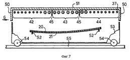
фиг. 7 представляет аналогичное поперечное сечение в направлении стрелок VII-VII фиг. 5;
фиг. 8 представляет вид механизма регулирования высоты экранов, показанных на фиг.7;
фиг. 9 иллюстрирует дополнительную часть этого механизма, не показанную на фиг. 8;
фиг. 10 представляет схематический график, на котором сравниваются перепады температур, полученные в результате измерений в известных туннельных печах и в соответствующей изобретению печи;
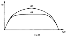
фиг. 11 представляет схематический график, на котором сравниваются поперечные профили кривизны стеклянных листов, изогнутых в соответствии с известным уровнем техники и в соответствии с предпочтительным вариантом осуществления изобретения;
фиг. 12 представляет вид сверху, аналогичный фиг. 3, но иллюстрирующий дополнительные экраны;
фиг. 13 представляет вид сверху, аналогичный фиг. 5, но иллюстрирующий дополнительные экраны.The invention is further illustrated, but not limited to the following description of some preferred embodiments of the invention with reference to the accompanying drawings, in which:
FIG. 1 is a schematic vertical sectional view of a glass bending furnace including a series of heating zones, some of which are used for bending;
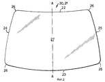
FIG. 2 is a plan view of a glass sheet that can be bent in the oven of FIG. 1;
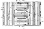
FIG. 3 is a greatly enlarged schematic top view of the heating system of FIG. 1 of one zone including six screens of the invention;
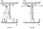
FIG. 4 (a) and (b) are schematic cross-sections of a small portion of a heated zone;
FIG. 5 is a plan view similar to FIG. 3, another heating system of another zone corresponding to FIG. 1;
FIG. 6 is a similarly enlarged cross-section taken in the direction of arrows VI-VI in FIG. 3;
FIG. 7 is a similar cross section in the direction of arrows VII-VII of FIG. 5;
FIG. 8 is a view of the screen height adjustment mechanism shown in FIG. 7;
FIG. 9 illustrates an additional part of this mechanism not shown in FIG. eight;
FIG. 10 is a schematic graph comparing temperature differences obtained from measurements in known tunnel kilns and in the furnace according to the invention;
FIG. 11 is a schematic graph comparing the transverse curvature profiles of glass sheets bent in accordance with the prior art and in accordance with a preferred embodiment of the invention;
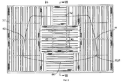
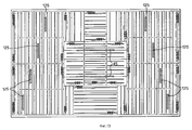
FIG. 12 is a plan view similar to FIG. 3, but illustrating additional screens;
FIG. 13 is a plan view similar to FIG. 5, but illustrating additional screens.
В показанной на фиг. 1 печи 1 для изгибания стекла стеклянные листы загружаются в кольцевые формы для изгибания под действием силы тяжести, нагреваются, изгибаются под воздействием силы тяжести (с дополнительным этапом давления или без него) так, чтобы согласоваться с конфигурацией кольцевой формы с требуемой степенью поперечной кривизны, отжигаются, дополнительно охлаждаются и выгружаются. На фиг.1 позицией S1 обозначен участок загрузки, S2 - участок равномерного нагревания, S3 - участок дифференциально излучаемого нагрева, S4 - участок нагрева с изгибающим дифференциально излучаемым нагревом, S5 - участок отжига, S6 - участок охлаждения и S7 - участок выгрузки. In the embodiment shown in FIG. 1 of the furnace 1 for bending glass, glass sheets are loaded into annular bending molds by gravity, heated, bent by gravity (with or without an additional pressure step) so as to conform to the configuration of the annular shape with the required degree of transverse curvature, annealed are additionally cooled and discharged. In Fig. 1, S1 denotes a loading section, S2 - a uniform heating section, S3 - a differentially radiated heating section, S4 - a heating section with bending differentially radiated heating, S5 - an annealing section, S6 - a cooling section, and S7 - a discharge section.
Каждый участок состоит из такого количества зон, которое необходимо, чтобы обеспечить требуемую пропускную способность и время цикла при условии, что каждая зона может держать одну кольцевую форму, а стеклянный лист (листы) на каждой форме должен оставаться на каждом участке в течение определенного периода времени. В этом типе печи стеклянные листы движутся не непрерывно, а последовательными этапами, так что форма, поддерживающая стеклянный лист (листы), остается неподвижной, точно расположенной в зоне в течение определенного интервалы времени до перемещения в следующую зону. Each section consists of as many zones as necessary to provide the required throughput and cycle time, provided that each zone can hold one annular shape, and the glass sheet (s) on each form must remain in each section for a certain period of time . In this type of furnace, glass sheets do not move continuously, but in successive steps, so that the shape supporting the glass sheet (s) remains stationary, precisely positioned in the zone for a certain amount of time before moving to the next zone.
Такая печь называется печью с периодической круговой подачей, а форма (и лист, поддерживаемый на форме), как полагают, должна индексироваться каждой последующей зоной по мере продвижения. При нормальной работе продвижение формы в такой печи осуществляется только в одном направлении, т.е. против часовой стрелки, если смотреть на фиг. 1. Such a furnace is called a periodic circular feed furnace, and the shape (and the sheet supported on the shape) is believed to be indexed by each subsequent zone as it moves. During normal operation, the advancement of the mold in such a furnace is carried out in only one direction, i.e. counterclockwise, as seen in FIG. 1.
Равномерный нагрев участка S2 по характеру может быть либо обычным, либо излучательным; цель заключается просто в том, чтобы энергия нагрева была по существу однородной от одной стороны каждой зоны до другой. The uniform heating of section S2 may be either conventional or radiative in nature; the goal is simply that the heating energy be substantially uniform from one side of each zone to the other.
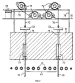
Кольцевые формы продвигаются через печь с помощью средства перемещения, которое дополнительно описывается в связи с фиг. 6. На каждом конце печи обеспечен механизм 10, 11, предназначенный для перемещения формы вместе со средством перемещения между верхним и нижним уровнями. The ring forms are advanced through the furnace by means of a conveyance, which is further described in connection with FIG. 6. At each end of the furnace, a mechanism 10, 11 is provided for moving the mold together with means for moving between the upper and lower levels.
Для перемещения на участие S3 или S4 можно использовать экраны и предпочтительные устройства, показанные на фиг.3-9, а также на фиг.12 и 13. To move to participation S3 or S4, you can use the screens and preferred devices shown in Fig.3-9, as well as in Fig.12 and 13.
На фиг. 2 показан стеклянный лист, который можно изогнуть в печи 1. Фактически, предпочтительный вариант осуществления соответствующей изобретению печи используют для изгибания стеклянных листов попарно, одного на другом, для изготовления сопряженной, вкладываемой одна в другое пары слоистого стекла, например, для ветрового стекла. Листы 20, 21 идентичны за исключением того, что верхний лист пары обычно несколько меньше для улучшения согласования после изгибания. Листы 20, 21 имеют длинные края 22, 23; короткие края 24, 25; углы 26 и среднюю часть 27. Листы имеют ось зеркальной симметрии А-А. Поперечная кривизна представляет кривизну в направлении от верхнего края 22 ("верхний" в отношении ветрового стекла, когда оно вставлено в автомобиль) к нижнему длинному краю 23, например, вдоль оси А-А. Конечно, изобретение не ограничено изгибанием листов показанной формы, в соответствии с изобретением можно изгибать листы любой формы. In FIG. 2 shows a glass sheet that can be bent in the furnace 1. In fact, a preferred embodiment of the invention according to the invention is used to bend glass sheets in pairs, one on top of the other, to make a pair of laminated glass that is inserted into one another, for example, for a windshield.
На фиг. 3 подробно иллюстрируется нагревательное устройство в зоне от участка S3 дифференциального нагревателя. Свод зоны оборудован удлиненными электрическими нагревательными элементами в различных нагревательных участках 30-34 в соответствии с длиной и ориентацией элементов, а среди элементов находится ряд экранов 35. Каждая область состоит из блоков, один из которых обозначен позицией 36, и каждый блок содержит от 1 до 4 элементов, причем выходную мощность каждого блока элементов можно регулировать отдельно. На чертежах контуры блоков показаны тонкими линиями, а нагревательные элементы 37 обозначены с помощью толстых линий, на нескольких из которых схематически показана намотка. Нагревательные элементы 37 могут быть любого удлиненного типа, подходящего для монтажа в изображенной конфигурации, и способные обеспечить требуемую плотность энергии. Например, элементы периферийных областей 30 и 31 имеют большую длину и меньшую плотность энергии, чем элементы центральной области 33, которые короче и имеют большую плотность энергии. Элементы областей 32 и 34 имеют промежуточные длину и плотность энергии относительно аналогичных параметров областей 30 и 31. Ссылаясь на уровни плотности энергии, принимают во внимание расположение элементов, а также их индивидуальный размер и номинальное значение энергии. Можно показать, что элементы с большей плотностью энергии предпочтительно используют рядом с экранами. In FIG. 3 illustrates in detail a heating device in an area from a differential heater portion S3. The arch of the zone is equipped with elongated electric heating elements in various heating sections 30-34 in accordance with the length and orientation of the elements, and among the elements there is a series of
Обычно используемый тип элемента имеет керамический сердечник с проволочным сопротивлением, намотанным вокруг этого сердечника. Там, где требуется большая мощность, можно использовать элементы с трубчатыми кварцевыми сердечниками, а там, где желательно упаковывать элементы плотно друг к другу, спиральную проволоку можно располагать внутри кварцевой трубки. A commonly used type of element has a ceramic core with a wire resistance wound around this core. Where high power is required, elements with tubular quartz cores can be used, and where it is desirable to pack the elements tightly together, the spiral wire can be placed inside the quartz tube.
Поскольку выходная мощность каждого блока регулируется независимо, там, где используются более короткие элементы, можно осуществить более точное управление мощностью, например, в 15 блоках образуют центральную область 33, потому что независимо регулируемые площади имеют меньший размер. Since the output power of each unit is independently regulated, where shorter elements are used, it is possible to carry out more precise power control, for example, in 15 blocks they form a
Направление движения стеклянных листов через зону показано стрелкой G. Когда стеклянные листы нагреваются или изгибаются для изготовления ветровых стекол или задних окон, ориентировать их предпочтительно необходимо так, чтобы их ось симметрии А-А была параллельна стрелке G, а контур листов 20, 21 показан в их индексированном местоположении, т.e. когда они неподвижны. Нашли, что при таких обстоятельства выгодно располагать элементы областей 30 и 31 параллельно этой оси симметрии, а элементы областей 32, 33 и 34 - под прямым углом к ней. Это помогает управлять подводом тепла к участкам, примыкающим к двум длинным краям 22, 23 листа, и, следовательно, управлять перепадами температур между центрами 27 листа и его длинными краями, чтобы получить требуемый поперечный профиль кривизны в стеклянном листе рядом с этими краями. The direction of movement of the glass sheets through the zone is indicated by arrow G. When the glass sheets are heated or bent to make windshields or rear windows, it is preferable to orient them so that their axis of symmetry AA is parallel to arrow G, and the outline of
В целях пояснения на фиг. 4 (a) и (b) схематически показан один основной нагревательный элемент 37 и один экран 35. Кроме того, показаны части листов 20, 21, включающие в себя первый выбранный участок 46, подлежащий нагреву до более высокой температуры, чем второй участок 47. Как показано на фиг. 4 (a), лучистая теплота, испускаемая элементом 37 в направлении K и L, падает прямо на первый выбранный участок 46 верхнего стеклянного листа 20 и значительная часть его передается нижнему листу 21. Однако тепло, излучаемое в направлении М, падает на экран и большей частью отражается и (или) рассеивается, как показано на рисунке. Тепло, излучаемое в направлении М, не достигает второго выбранного участка 47, как это было бы в противном случае. Поэтому экран 35 направляет тепло путем двойного действия экранирования выбранного участка 47, подлежащего меньшему нагреву, и отражения (рассеивания) тепла по направлению к выбранному участку 46, подлежащему большему нагреву. For purposes of explanation, in FIG. 4 (a) and (b) schematically shows one
На фиг. 4 (b) показаны разные расстояния, на которые будет производиться ссылка во время описания предпочтительных размеров и конфигураций экранов. Линия B-B представляет уровень основных нагревательных элементов; расстояние "x" является расстоянием от уровня элементов до (верхнего) стеклянного листа в его изогнутом состоянии; расстояние "y" представляет участок экрана, который расположен между основными нагревательными элементами и стеклянным листом, т.е. рабочий участок, и расстояние "y" является расстоянием от ближайшего к стеклянному листу края экрана до листа. Очевидно, что x = y + z. In FIG. 4 (b) shows the different distances that will be referenced during the description of the preferred screen sizes and configurations. Line B-B represents the level of the main heating elements; the distance "x" is the distance from the level of the elements to the (upper) glass sheet in its curved state; the distance "y" represents a portion of the screen that is located between the main heating elements and the glass sheet, i.e. work area, and the distance "y" is the distance from the edge of the screen closest to the glass sheet to the sheet. Obviously, x = y + z.
Количество экранов 35 может меняться от одного в общем до одного на нагревательный элемент 37 - в зависимости от характера профиля распределения температур, который нужно получить. Подобно этому распределение экранов внутри зоны можно делать симметричным или асимметричным. Ориентация экрана определяется практически путем ориентации нагревательных элементов, рядом с которыми должен быть размещен экран. Как объяснялось выше, ориентацию нагревательных элементов можно менять в соответствии с тем, какой профиль распределения температур пытаются создать. В примере стеклянного листа для ветрового стекла часто оказывается необходимым определять профиль распределения температур от одного длинного края листа через центр до другого длинного края, постольку это влияет на получаемый поперечный профиль кривизны. The number of
Там, где желательно получить большой перепад температур между центром и краем стеклянного листа, требуется больше экранов для направления тепла, излучаемого элементами центральной области 33 (фиг. 3) по направлению к центральной части стекла, и предотвращения попадания тепла на более холодные края. Поэтому в этой ситуации вначале размещают экран в центральной области 33, а дополнительные экраны обычно необходимо размещать только в периферийных областях, например, в областях 32 и 34, когда область 33 окажется заполненной. Каждый экран эффективно уменьшает площадь стеклянного листа, нагреваемую элементами рядом с экраном, т.е. снижает эффективный угол излучения тепла от соседних элементов. Where it is desirable to obtain a large temperature difference between the center and the edge of the glass sheet, more screens are required to direct the heat radiated by the elements of the central region 33 (FIG. 3) towards the central part of the glass and to prevent heat from reaching the colder edges. Therefore, in this situation, the screen is first placed in the
Исходя из этого на участке 3, где желательны относительно высокие перепады температур между центром и краями в 40-55oC, используются шесть экранов 35 и только два используются на участке изгибания 4, потому что к этому моменту требуемый перепад температур в стеклянном листе в основном создан.Based on this, in
Ясно, что экраны (независимо от участка, в котором их используют) нужно делать из теплостойкого материала, достаточно прочного, способного обеспечить достаточный срок службы, и предпочтительно достаточно жесткого, чтобы сохранять свою форму (особенно если он размещен под углом к вертикали), хотя подвешенные к кровле печи экраны можно делать из теплостойкой ткани. Подходящим материалом является материал "Фиберфракс Дюраборд" (товарный знак), изготавливаемый компанией "Карборундум резистант материалу Лтд.", г. Рейнфорд, о. Святой Елены, граф. Морсисайд, Соединенное Королевство. Это жесткая, высокотермостойкая пластина, сделанная из алюмосиликатных волокон и органических связующих агентов. Подобная продукция имеется у других изготовителей огнеупорных экранов. Низкая плотность и легкость разрезания помогают быстро и легко устанавливать экраны. Однако для обеспечения более длительного срока службы предпочитают использовать составной экран, состоящий из сердечника из прочного материала типа кварцевого стекла, карбида кремния или нитрида кремния либо металла типа стали, облицованной бумагой "Фиберфракс" (товарный знак) для малоэффективной тепловой массы. В качестве альтернативы, экраны, сделанные из aлюмосиликатных панелей типа "Фиберфракс Дюраборд" можно сделать более жесткими и прочными путем нанесения укрепляющих растворов типа "Ригидизер W", также имеющимися у компании "Карборундум резистант материалз Лтд.". It is clear that the screens (regardless of the area in which they are used) need to be made of heat-resistant material, strong enough to provide a sufficient service life, and preferably rigid enough to maintain its shape (especially if it is placed at an angle to the vertical), although screens suspended from the roof of the oven can be made of heat-resistant fabric. Suitable material is Fiberfrax Durabord (trademark) material manufactured by Carborundum Resistance to Material Ltd., Rhinford, about. St. Helena, Count. Morsyside, United Kingdom. It is a tough, highly heat-resistant plate made of aluminosilicate fibers and organic binders. Other refractory screen manufacturers have similar products. Low density and ease of cutting help to quickly and easily install screens. However, to ensure a longer service life, it is preferable to use a composite screen consisting of a core made of a durable material such as quartz glass, silicon carbide or silicon nitride, or a metal such as steel coated with Fiberfrax paper (trademark) for an ineffective thermal mass. Alternatively, screens made from aluminosilicate panels of the Fiberfrax Dyurabord type can be made more rigid and durable by applying reinforcing solutions of the Rigidizer W type, also available from Carborundum Resistance Materials Ltd.
Кроме того, можно управлять перепадами температур с помощью изменения лучепоглотительной способности используемого материала. Материал с низкой лучепоглощательной способностью типа "Фиберфракс Дюраборд" отражает большую часть падающего на него теплового излучения, чем материал с более высокой лучепоглощательной способностью типа стали. Следовательно, экран с поверхностью из материала "Дюраборд" более эффективен при направляющем тепле и таким образом вызывает больший перепад температур для данного размера и местоположения экрана, чем экран со стальной поверхностью. In addition, temperature differences can be controlled by changing the absorbance of the material used. Fiberfrax Durabord type material with a low radiation absorption reflects a greater part of the thermal radiation incident on it than a material with a higher radiation absorption type like steel. Therefore, a screen with a surface made of Durabord material is more effective in directing heat and thus causes a greater temperature difference for a given size and location of the screen than a screen with a steel surface.
На фиг.5 показана зона участка изгибания 4. Применимы те же соображения относительно размера, типа, плотности энергии и распределения нагревательных элементов, как описано относительно фиг.3. Элементы аналогичным образом расположены в периферийных областях 40, 41, 42, 44 и центральной области 43. Благотворное влияние экранов, предотвращающих излучение тепла на центральную область 43, означает, что на практике нет необходимости устанавливать, особенно в этой зоне, такую высокую выходную энергию элементов, что, в свою очередь, имеет преимущества, особенно в отношении оптических свойств изготавливаемого стекла. FIG. 5 shows the area of the bending portion 4. The same considerations apply for the size, type, energy density and distribution of the heating elements, as described with respect to FIG. 3. The elements are similarly located in the
Вышеприведенные комментарии относительно количества, расположения и типа экранов применимы также к участку 4. Поскольку перепады температуры между центром и краями уже в основном достигнуты в стеклянном листе, т.е. центр листа уже значительно горячее, чем края, нет необходимости делать перепады на участке 4 такими же большими, как на участке 3, обычно составляющими здесь 30- 40oC, и достаточно двух экранов 45. Они помещены близко к краю центральной области 43 для предотвращения излучения тепла на участки стеклянного листа ниже периферийных областей 42 и 44.The above comments regarding the number, location and type of screens are also applicable to section 4. Since the temperature differences between the center and the edges are already mainly achieved in the glass sheet, i.e. the center of the sheet is already much hotter than the edges, there is no need to make the differences in section 4 as large as in
На фиг. 6 показан поперечный разрез фиг.3 по линии VI-VI. На ней показаны перегородки 50 между соседними зонами, часть конструкции печи, включающую в себя свод печи 51, и элементы областей 32, 33 и 34 вместе с экранами 35. На фиг.6 также показано предпочтительное средство перемещения в виде ящика 53, содержащее кольцевую форму 52 и обеспеченное четырьмя колесами 64 (из которых показаны два), которые движутся по рельсам 55, идущим вдоль печи. Для приведения в движение ящиков по рельсам обеспечен также подходящий обычный приводной механизм (не показанный). Кольцевая форма 52 представляет обычную кольцевую форму для изгибания под действием силы тяжести и показана здесь в поперечном разрезе. Верхняя поверхность кольцевой формы определяет местоположение, которое должна занимать пара стеклянных листов, а на фиг.7 показана пара листов 20, 21, занимающих такое положение, поддерживаемых формой. На фиг.6 листы 20, 21 еще плоские и поэтому они только соприкасаются с кольцевой формой в областях, соседних с короткими краями 24, 25 листов. Эти области, конечно, не показаны на фиг.6, на которой изображен поперечный разрез по осевой линии печи; отсюда между листами и формой на фиг.6 показан зазор. In FIG. 6 is a cross-sectional view of FIG. 3 along line VI-VI. It shows
Не важно, что экраны 35 проходят между соседними нагревательными элементами: рабочий участок можно подвешивать ниже элементов. Однако экран удобно располагать между элементами к своду 51 для того, чтобы поддерживать экраны без необходимости применения другого средства подвешивания. Длину экранов 35 можно изменять на любом участке в соответствии с требуемым перепадом температур между центром и краем. Предпочтительно иметь возможность осуществлять регулирование протяжения, до которого должны простираться экраны за пределы элементов, с внешней стороны печи, чтобы можно было управлять создаваемым профилем распределения температур в стеклянном листе, управляя таким образом и позволяя осуществлять оптимизирование получаемого в результате профиля изгиба, и все это без прерывания прохождения стеклянных листов через систему. В общем, чем дальше экраны проходят за пределы элементов, тем достигается более локализованный нагрев и получается больший перепад температур между центром и краем. После получения оптимизированных установок для различной изготавливаемой продукции такая возможность регулирования позволяет быстро изменять установки и, следовательно, быстро перенастраиваться с одного изделия на другое. It does not matter that the
Расстояние между основными элементами и полностью изогнутыми стеклянными листами в центральных местоположениях экрана фиг.6 равно 330 мм. Конечно, в других местоположениях экрана будут получены несколько иные расстояния из-за меняющейся кривизны листа. Кроме того, расстояние будет другим, если измерение произведено во время действительного процесса изгибания до того, как стеклянный лист примет свою окончательную форму. Рабочий участок экрана может простираться на 30 мм (9% от 330 мм) для начального действия направления тепла. Для более высокого действия рабочий участок может простираться на 90 мм (27% от 330 мм), 150 мм (45% от 330 мм), 230 мм (70% от 330 мм) или на любую промежуточную величину. На практике, в случае автоматизирования регулирования экрана, как будет описано ниже, возможно выполнение еще большего рабочего участка. The distance between the main elements and the fully curved glass sheets at the central locations of the screen of FIG. 6 is 330 mm. Of course, in other locations of the screen, slightly different distances will be obtained due to the changing curvature of the sheet. In addition, the distance will be different if the measurement is taken during the actual bending process before the glass sheet takes its final shape. The working portion of the screen can extend 30 mm (9% of 330 mm) for the initial action of the direction of heat. For higher performance, the work area can extend over 90 mm (27% from 330 mm), 150 mm (45% from 330 mm), 230 mm (70% from 330 mm) or any intermediate value. In practice, in the case of automating the adjustment of the screen, as will be described below, it is possible to perform an even larger work area.
Как упоминалось выше, с точки зрения монтажа удобно, когда экран проходит вверх, в свод печи. Однако не имеет существенного значения, каким образом рабочий участок экрана подвешивать с помощью, например, стержней или проволок. В этом случае верхняя часть экрана предпочтительно находится на уровне элементов. Но и здесь это не важно, поскольку все же получается действие направления тепла, когда между уровнем элементов и уровнем вершины экрана имеется промежуток. Этот промежуток может составлять 50 мм (15% от 330 мм), 100 мм (30% от 330 мм) или любую промежуточную величину. As mentioned above, from the point of view of installation, it is convenient when the screen goes up into the arch of the furnace. However, it does not matter how to suspend the working portion of the screen using, for example, rods or wires. In this case, the upper part of the screen is preferably at the element level. But here it is not important, since the effect of the direction of heat is obtained when there is a gap between the level of elements and the level of the top of the screen. This gap may be 50 mm (15% of 330 mm), 100 mm (30% of 330 mm) or any intermediate value.
На фиг. 7 показан поперечный разрез фиг.5 по линии VIII-VIII и он принципиально отличается от фиг.6 тем, что вместо шести экранов 35 показаны два экрана 45. Комментарии в отношении фиг.6 применимы к фиг.7 с соответствующими изменениями. На стадии, показанной на этом чертеже, пара стеклянных листов 20, 21 провисает по существу единообразно с кольцевой формой 52. In FIG. 7 is a cross-sectional view of FIG. 5 along line VIII-VIII and is fundamentally different from FIG. 6 in that instead of six
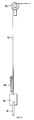
Вышеупомянутый предпочтительный способ обеспечения возможности регулирования экранов с внешней стороны печи показан на фиг. 8 и 9. The aforementioned preferred method of enabling screens to be controlled from the outside of the furnace is shown in FIG. 8 and 9.
На фиг. 8 изображена центральная часть фиг.7, т.е. поперечный разрез через зону на участке изгибания 4, но более подробно и с добавлением одного возможного механизма регулирования. Экраны 45 подвешены на тросах 70, которые проходят сквозь свод 51 через расточенные отверстия 74 и вокруг шкивов 71, которые размещены на раме 75. Поскольку сами экраны могут быть очень легкими, к каждому тросу можно также подвесить груз 72. После прохождения вокруг шкивов 71 тросы 70 проходят вокруг следующих, горизонтально ориентированных шкивов 76 (показан только один из них), так что каждый трос движется под прямым углом и выходит из плоскости чертежа к следующей части механизма, показанной на фиг. 9. В своде 51 обеспечены прорези 73 так, что экраны 45 можно при необходимости втягивать. In FIG. 8 shows the central part of FIG. 7, i.e. cross-section through the zone in the bending section 4, but in more detail and with the addition of one possible regulation mechanism. The
Остальная часть механизма показана на фиг.9. Эта часть механизма обычно может находиться на боковой стороне соответствующего участки, т.е. плоскость фиг.9 находится под прямым углом к фиг.6. Трос 70 проходит вокруг шкива 80 и направляется к механизму наматывания 31. The rest of the mechanism is shown in Fig.9. This part of the mechanism can usually be on the side of the corresponding sections, i.e. the plane of FIG. 9 is at right angles to FIG. 6. A
Обеспечен противовес 82, который имеет шкалу и указатель 83, по которым можно устанавливать положение экрана относительно элементов в зоне нагрева. Для каждого регулируемого экрана обеспечен соответствующий механизм. A
В качестве альтернативы регулирование любого экрана можно автоматизировать с помощью серводвигателя. Не говоря об удобстве и экономии труда, это имеет дополнительное преимущество, обеспечивая практическую возможность использования экранов очень близко к стеклянному листу. Постоянное расположение экрана так близко к стеклянному листу, чтобы он оказался ниже периферии кольцевой формы, может привести к загораживанию экраном формы при продвижении формы от одной зоны в следующую. Механизированное устройство регулирования с управлением от микропроцессора можно запрограммировать на поднятие экранав при каждом перемещении формы и возвращение его для следующего стеклянного листа. Таким способом можно использовать экраны, простирающиеся до 85% от расстояния элементов до полностью изогнутого стеклянного листа, т.е. до расстояния в пределах 50 мм от стеклянного листа и 280 мм от элементов. Alternatively, the control of any screen can be automated with a servomotor. Not to mention the convenience and economy of labor, this has an additional advantage, providing the practical possibility of using screens very close to the glass sheet. The constant location of the screen so close to the glass sheet so that it is below the periphery of the annular shape, can lead to screen obstruction of the form when moving the form from one zone to the next. A mechanized control device controlled by a microprocessor can be programmed to raise the screen every time the mold is moved and return it for the next glass sheet. In this way, you can use screens that extend up to 85% of the distance of the elements to a fully curved glass sheet, i.e. up to a distance of 50 mm from the glass sheet and 280 mm from the elements.
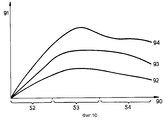
Действие регулирования протяженности рабочего участка экранов показано на фиг.10, на которой ось x 90 представляет зоны нагрева участков S2, S3, и S4, а ось Y 91 представляет перепады температуры, получаемые между центром и длинным краем стеклянного листа. Линия 92 показывает результаты, полученные в известной печи без экранов (фактически в описанной выше печи, но с изъятыми экранами), тогда как линия 93 показывает результаты, полученные в описанной выше печи, когда рабочий участок простирается на 90 мм ниже нагревательных элементов с расстоянием 240 мм между экранами и стеклянным листом. Линия 94 снова показывает результаты, полученные в соответствующей изобретению печи, где протяженность рабочего участка увеличена до 150 мм при расстоянии между экранами и стеклянным листом 180 мм. Были получены перепады температуры между центром и краем вплоть до 55oC с шестью экранами на участке S3 и вплоть до 40oC с двумя экранами на участке S4. Принимая во внимание, что в случае самого последнего состояния существующей техники обычно можно достигнуть перепадов температур 20 - 25oC, как это представлено линией 92, перепады, получаемые с помощью изобретения, удивительно высокие, и полезные улучшения в отношении перепада температур между центром и краем получены в случае рабочих участков длиной до 30 мм. Поэтому изобретение представляет значительный прогресс по сравнению с известным уровнем техники и обеспечило возможность изгибать, например, стеклянные листы для ветровых стекол сложный формы с поперечной кривизной до 25 мм при удовлетворительном поперечном профиле кривизны, сильно улучшая тем самым плохие характеристики стеклоочистителя и оптическое искажение, получаемое из-за плоской или обратной кривизны. Конечно, для каждой различной формы стекла могут оказаться необходимыми разные распределения экранов и протяженности рабочих участков и в целях оптимизации настроек для каждой формы стекла желательно некоторое первоначальное экспериментирование.The action of adjusting the length of the working section of the screens is shown in Fig. 10, in which the x-axis represents the heating zones of sections S2, S3, and S4, and the Y-
Пример улучшения формы, полученной с использованием изобретения, показан на фиг.11, на которой ось x 100 представляет расстояние вдоль образца стеклянного листа, измеряемое от длинного края, в качестве которого может быть нижний край, если бы лист был частью установленного ветрового стекла, по направлению к противоположному длинному краю. Ось y 101 представляет полученный уровень поперечной кривизны, а кривая 102 иллюстрирует полученный поперечный профиль кривизны в стеклянном листе, изогнутом в соответствии с известным уровнем техники. Явно видна плоская средняя часть стеклянного листа. С помощью описанного выше соответствующего использования экранов на участках дифференциального нагрева S3 и S4 печи был произведен изгиб стеклянного листа, на котором произведено измерение поперечного профиля кривизны 103. Плоская средняя область была установлена, а полученный профиль оказался близким к заданному однообразно цилиндрическому поперечному профилю кривизны. An example of an improvement in shape obtained using the invention is shown in FIG. 11, in which the x 100 axis represents the distance along the sample of the glass sheet, measured from the long edge, which could be the lower edge if the sheet were part of an installed windshield, towards the opposite long edge.
Хотя изобретение полезно для применения при улучшении цилиндрического профиля поперечной кривизны, это не означает, что оно ограничивается им и его можно также использовать, например, в изготовлении S-образной поперечной кривизны. В этой ситуации профиль поперечной кривизны ветрового стекла поворачивается на 180o по направлению к его нижнему краю, т.е. к капоту автомобиля; другими словами существует точка перегиба. Создание такого профиля поперечной кривизны требует точного управления профилем распределения температур в стеклянном листе с обеих сторон от точки перегиба во время изгибания: это является ситуацией, при которой уместен тщательный выбор асимметричного распределения экранов.Although the invention is useful for improving the cylindrical profile of transverse curvature, this does not mean that it is limited to it and can also be used, for example, in the manufacture of S-shaped transverse curvature. In this situation, the profile of the transverse curvature of the windshield is rotated 180 o in the direction of its lower edge, i.e. to the hood of the car; in other words, there is an inflection point. Creating such a profile of transverse curvature requires precise control of the temperature distribution profile in the glass sheet on both sides of the inflection point during bending: this is a situation in which careful selection of asymmetric distribution of screens is appropriate.
Другая ситуация, при которой может оказаться полезно использовать изобретение, возникнет тогда, когда ветровое стекло необходимо согласовывать с контуром крыши кузова транспортного средства, т. е. самая верхняя часть ветрового стекла, по существу, оказывается параллельной контуру крыши кузова в точке соприкосновения. Это требует изменения радиуса поперечной кривизны в верхней части ветрового стекла, что в свою очередь требует особого профиля распределения температур во время нагревания и изгибания и в этом случае подходит асимметричное распределение экранов. Another situation in which it may be useful to use the invention will arise when the windshield needs to be matched with the contour of the roof of the vehicle body, i.e. the uppermost part of the windshield is essentially parallel to the contour of the roof of the body at the point of contact. This requires a change in the radius of transverse curvature in the upper part of the windshield, which in turn requires a special temperature distribution profile during heating and bending, in which case an asymmetric distribution of screens is suitable.
Изобретение можно также использовать для сообщения избыточного тепла коротким краям ветрового стекла, например, потому, что требуется более глубокий изгиб рядом с опорой А. На фиг.12 показана зона от участки S3 дифференциального предварительного нагрева, в которой добавлено восемь дополнительных экранов 115, смонтированных таким образом, чтобы предотвратить доступ дополнительного тепла от нагревателей, находящихся рядом с короткими краями, по направлению к центру ветрового стекла. На фиг.12 показано обычное расположение экранов, т.е. не предназначенное для конкретной формы лобового стекла, для распределения нагрева, не особенного критического на этой стадии. The invention can also be used to communicate excess heat to the short edges of the windshield, for example, because deeper bending is required next to the support A. FIG. 12 shows the area from the differential preheating sections S3 in which eight
В качестве сравнения на фиг.13 показана зона от участка S4 изгибания (с дифференциальным нагревом), в которой добавлено восемь дополнительных экранов 125 при таком расположении, которое приспосабливается для конкретной формы ветрового стекла. На этой стадии, более поздней, когда происходит активное изгибание, может появиться желание обеспечить по существу больше тепла на коротких краях, а специально приспособленное расположение позволяет точнее управлять этим дополнительным теплом, ограничивая его попадание на краевые части стеклянного листа. As a comparison, FIG. 13 shows a region from a bending portion S4 (with differential heating) in which eight
Показанное на фиг.13 расположение полезно также в тех случаях, когда появляется нежелательная инверсия кривизны по направлению к углам стеклянного листа, потому что стеклянный лист не провисает на самих углах во время изгибания. Это можно облегчить путем повышения температуры этой части стеклянного листа на последующей стадии в процессе изгибания. The arrangement shown in FIG. 13 is also useful in cases where an undesirable inversion of curvature appears towards the corners of the glass sheet because the glass sheet does not sag at the corners themselves during bending. This can be alleviated by raising the temperature of this part of the glass sheet in a subsequent step in the bending process.
Путем использования точно расположенных экранов требуемое дополнительное тепло можно направить точнее, чем в случае, если бы была просто увеличена выходная мощность нагревательных элементов над этой частью стеклянного листа. Это также является состоянием, когда особенно полезно использование регулируемых экранов, поскольку протяженность рабочего участка можно увеличивать в соответствующее время в процессе изгибания. By using precisely arranged screens, the required additional heat can be directed more accurately than if the output of the heating elements above this part of the glass sheet was simply increased. This is also a condition where the use of adjustable screens is particularly useful, since the length of the working section can be increased at an appropriate time during the bending process.
Настоящее изобретение облегчает многие из проблем, присущих известной технике. Оборудовать таким образом необходимо только конкретные зоны нагрева в печах, в которых действительно требуются экраны. Таким образом устраняются расходы на оборудование каждой формы или другого поддерживающего средства для стеклянных листов устройствами типа известных экранов или поглотителей тепла. Кроме того, поскольку соответствующие настоящему изобретению экраны связаны только с конкретными зонами нагрева печи, где они необходимы, они не создают описанных выше имеющихся в других местах проблем загрузки или отжига. The present invention alleviates many of the problems inherent in the prior art. It is only necessary to equip in this way only specific heating zones in furnaces in which screens are really required. This eliminates the cost of equipment of each form or other supporting means for glass sheets by devices such as known screens or heat absorbers. In addition, since the screens of the present invention are only associated with specific heating zones of the furnace where they are needed, they do not create the loading or annealing problems described above at other places.
Возможно лучшее управление профилем распределения температур по всему стеклянному листу, и достигаются более высокие перепады температур между центром и краем, чем можно было получить до сих пор обычным способом. Perhaps better control of the temperature distribution profile over the entire glass sheet, and higher temperature differences are achieved between the center and the edge than could be obtained so far in the usual way.
Claims (22)
Applications Claiming Priority (2)
| Application Number | Priority Date | Filing Date | Title |
|---|---|---|---|
| GB939326288A GB9326288D0 (en) | 1993-12-23 | 1993-12-23 | Glass bending system |
| GB9326288.9 | 1993-12-23 |
Publications (2)
| Publication Number | Publication Date |
|---|---|
| RU94044525A RU94044525A (en) | 1996-10-27 |
| RU2137723C1 true RU2137723C1 (en) | 1999-09-20 |
Family
ID=10747091
Family Applications (1)
| Application Number | Title | Priority Date | Filing Date |
|---|---|---|---|
| RU94044525A RU2137723C1 (en) | 1993-12-23 | 1994-12-22 | Furnace and method of bending glass |
Country Status (19)
| Country | Link |
|---|---|
| US (1) | US5656052A (en) |
| EP (1) | EP0659697B1 (en) |
| JP (1) | JPH07277754A (en) |
| KR (1) | KR950017775A (en) |
| CN (1) | CN1070824C (en) |
| AT (1) | ATE192422T1 (en) |
| AU (1) | AU686682B2 (en) |
| BR (1) | BR9405196A (en) |
| CA (1) | CA2138620A1 (en) |
| DE (1) | DE69424266D1 (en) |
| FI (1) | FI110606B (en) |
| GB (1) | GB9326288D0 (en) |
| NZ (1) | NZ270138A (en) |
| PL (1) | PL177000B1 (en) |
| RO (1) | RO111359B1 (en) |
| RU (1) | RU2137723C1 (en) |
| TR (1) | TR28068A (en) |
| TW (1) | TW267995B (en) |
| ZA (1) | ZA9410291B (en) |
Cited By (2)
| Publication number | Priority date | Publication date | Assignee | Title |
|---|---|---|---|---|
| RU2753297C2 (en) * | 2016-11-30 | 2021-08-12 | Сэн-Гобэн Гласс Франс | Thin glass forming |
| US11964896B2 (en) | 2017-06-29 | 2024-04-23 | Saint-Gobain Glass France | Bending of glass sheets comprising localized cooling |
Families Citing this family (21)
| Publication number | Priority date | Publication date | Assignee | Title |
|---|---|---|---|---|
| FI97292C (en) * | 1995-04-04 | 1996-11-25 | Tamglass Eng Oy | Method for transferring glass sheet transport carts in a glass sheet bending furnace and a glass sheet bending furnace |
| US6240746B1 (en) * | 1997-04-04 | 2001-06-05 | Asahi Glass Company Ltd. | Glass plate bending method and apparatus |
| FI106256B (en) * | 1998-02-18 | 2000-12-29 | Tamglass Ltd Oy | Method and apparatus for directing the heating in a curing oven for glass sheets |
| DE60039774D1 (en) * | 1999-08-26 | 2008-09-18 | Agc Flat Glass Europe Sa | COMPOSITE GLASS |
| JP4457438B2 (en) * | 1999-09-27 | 2010-04-28 | 旭硝子株式会社 | Glass plate bending apparatus and method |
| FI109199B (en) * | 2001-02-28 | 2002-06-14 | Tamglass Ltd Oy | Arrangement for bending glass plates |
| US20050092028A1 (en) * | 2003-11-05 | 2005-05-05 | William Blanc | Light weight gravity bending ring |
| DE102006024484B3 (en) | 2006-05-26 | 2007-07-19 | Saint-Gobain Sekurit Deutschland Gmbh & Co. Kg | Device for heating or bending glass panes has furnace section with controllable heating elements to form heating zones matching dimensions of glass panes passing through in transport moulds on transport carriage |
| JP5359887B2 (en) | 2007-12-28 | 2013-12-04 | 旭硝子株式会社 | Glass plate forming heating apparatus and glass plate bending method |
| US20110265515A1 (en) * | 2008-12-22 | 2011-11-03 | Alberto Hernandez Delsol | Method and system for bending glass sheets with complex curvatures |
| FR2944345B1 (en) * | 2009-04-08 | 2013-03-22 | Saint Gobain | OVEN COMPRISING A THERMAL BARRIER |
| EP2457881B1 (en) | 2010-11-30 | 2019-05-08 | Corning Incorporated | Method and apparatus for bending a sheet of material into a shaped article |
| JP2015501274A (en) * | 2011-10-10 | 2015-01-15 | コーニング インコーポレイテッド | Apparatus and method for forming a bend without slack in a thin glass sheet |
| US8816252B2 (en) * | 2011-11-22 | 2014-08-26 | Corning Incorporated | Methods and apparatus for localized heating and deformation of glass sheets |
| KR101495762B1 (en) * | 2012-04-09 | 2015-02-25 | 주식회사 엘지화학 | Float bath and glass manufacturing apparatus |
| CN102757169B (en) * | 2012-07-20 | 2014-08-20 | 福耀玻璃工业集团股份有限公司 | Bending furnace and method for bending glass plate |
| FI127228B2 (en) | 2013-05-23 | 2022-11-15 | Taifin Glass Machinery Oy | Method for heating glass sheets, and glass tempering furnace |
| JP2016525059A (en) * | 2013-07-16 | 2016-08-22 | コーニング インコーポレイテッド | Apparatus and method for bending thin glass |
| EP3145881B1 (en) | 2014-05-23 | 2019-07-31 | Corning Incorporated | Radiation shield for shaping thin glass |
| KR102368787B1 (en) * | 2015-10-08 | 2022-03-03 | 삼성디스플레이 주식회사 | Thermoforming method and thermoforming apparatus |
| US11702356B2 (en) * | 2019-04-15 | 2023-07-18 | Corning Incorporated | Assemblies and methods for bending glass |
Family Cites Families (16)
| Publication number | Priority date | Publication date | Assignee | Title |
|---|---|---|---|---|
| BE544819A (en) * | 1955-02-14 | |||
| US2794300A (en) * | 1956-01-31 | 1957-06-04 | Pittsburgh Plate Glass Co | Glass bending lehrs |
| BE595770A (en) * | 1959-10-09 | |||
| US3249415A (en) * | 1964-12-24 | 1966-05-03 | Permaglass | Apparatus for heat treating glass sheets |
| US3457060A (en) * | 1966-03-23 | 1969-07-22 | Libbey Owens Ford Co | Glass bending furnace with partitions defining separate longitudinally disposed heating areas |
| US4111676A (en) * | 1977-06-27 | 1978-09-05 | Ppg Industries, Inc. | Adaptation of glass shaping means for tempering flat glass |
| US4687501A (en) * | 1986-04-21 | 1987-08-18 | Ppg Industries, Inc. | Lightweight bending iron heat shields for glass bending molds |
| GB2201670B (en) * | 1987-02-27 | 1991-09-18 | Electricity Council | Glass forming apparatus |
| EP0338216B1 (en) * | 1988-02-25 | 1994-11-23 | Asahi Glass Company Ltd. | Method of and an apparatus for bending glass plates for a laminated glass |
| JPH01252886A (en) * | 1988-03-31 | 1989-10-09 | Central Glass Co Ltd | Heat working furnace and heat treatment effected thereby |
| US5176733A (en) * | 1988-12-27 | 1993-01-05 | Ford Motor Company | Method and apparatus for directed energy glass heating |
| FR2658808B1 (en) * | 1990-02-21 | 1993-05-14 | Saint Gobain Vitrage Int | OVEN FOR BOMBING GLASS SHEETS BY COLLAPSE ON A BOMBING FRAME AND ITS APPLICATION TO THE PRODUCTION OF GLAZES OF COMPLEX FORM. |
| EP0486952B1 (en) * | 1990-11-19 | 1995-10-18 | Tamglass Engineering Oy | Method for heating and bending a glass sheet |
| US5085580A (en) * | 1990-11-30 | 1992-02-04 | Glasstech, Inc. | Preheater for flat glass sheets |
| IT1246032B (en) * | 1991-03-08 | 1994-11-07 | Poppi Spa | HARDENING OVEN, IN PARTICULAR FOR GLASS AND SIMILAR SHEETS. |
| EP0592862B1 (en) * | 1992-10-15 | 1997-03-12 | Tamglass Engineering Oy | Method and furnace for bending glass sheets |
-
1993
- 1993-12-23 GB GB939326288A patent/GB9326288D0/en active Pending
-
1994
- 1994-12-14 NZ NZ270138A patent/NZ270138A/en unknown
- 1994-12-15 AU AU80479/94A patent/AU686682B2/en not_active Ceased
- 1994-12-16 AT AT94309435T patent/ATE192422T1/en not_active IP Right Cessation
- 1994-12-16 DE DE69424266T patent/DE69424266D1/en not_active Expired - Lifetime
- 1994-12-16 EP EP94309435A patent/EP0659697B1/en not_active Expired - Lifetime
- 1994-12-16 TW TW083111766A patent/TW267995B/zh active
- 1994-12-20 RO RO94-02060A patent/RO111359B1/en unknown
- 1994-12-20 US US08/360,083 patent/US5656052A/en not_active Expired - Fee Related
- 1994-12-20 CA CA002138620A patent/CA2138620A1/en not_active Abandoned
- 1994-12-20 PL PL94306396A patent/PL177000B1/en unknown
- 1994-12-21 BR BR9405196A patent/BR9405196A/en not_active IP Right Cessation
- 1994-12-21 TR TR01342/94A patent/TR28068A/en unknown
- 1994-12-22 CN CN94119190A patent/CN1070824C/en not_active Expired - Fee Related
- 1994-12-22 RU RU94044525A patent/RU2137723C1/en not_active IP Right Cessation
- 1994-12-22 JP JP6320469A patent/JPH07277754A/en active Pending
- 1994-12-22 ZA ZA9410291A patent/ZA9410291B/en unknown
- 1994-12-22 KR KR1019940036680A patent/KR950017775A/en not_active Application Discontinuation
- 1994-12-23 FI FI946087A patent/FI110606B/en active
Cited By (2)
| Publication number | Priority date | Publication date | Assignee | Title |
|---|---|---|---|---|
| RU2753297C2 (en) * | 2016-11-30 | 2021-08-12 | Сэн-Гобэн Гласс Франс | Thin glass forming |
| US11964896B2 (en) | 2017-06-29 | 2024-04-23 | Saint-Gobain Glass France | Bending of glass sheets comprising localized cooling |
Also Published As
| Publication number | Publication date |
|---|---|
| JPH07277754A (en) | 1995-10-24 |
| RO111359B1 (en) | 1996-09-30 |
| KR950017775A (en) | 1995-07-20 |
| DE69424266D1 (en) | 2000-06-08 |
| TW267995B (en) | 1996-01-11 |
| ATE192422T1 (en) | 2000-05-15 |
| EP0659697B1 (en) | 2000-05-03 |
| RU94044525A (en) | 1996-10-27 |
| ZA9410291B (en) | 1995-06-23 |
| EP0659697A3 (en) | 1996-01-10 |
| US5656052A (en) | 1997-08-12 |
| FI110606B (en) | 2003-02-28 |
| AU686682B2 (en) | 1998-02-12 |
| PL177000B1 (en) | 1999-09-30 |
| NZ270138A (en) | 1996-10-28 |
| GB9326288D0 (en) | 1994-02-23 |
| CA2138620A1 (en) | 1995-06-24 |
| AU8047994A (en) | 1995-06-29 |
| BR9405196A (en) | 1995-08-01 |
| TR28068A (en) | 1996-01-02 |
| CN1121052A (en) | 1996-04-24 |
| PL306396A1 (en) | 1995-06-26 |
| CN1070824C (en) | 2001-09-12 |
| FI946087A (en) | 1995-06-24 |
| FI946087A0 (en) | 1994-12-23 |
| EP0659697A2 (en) | 1995-06-28 |
Similar Documents
| Publication | Publication Date | Title |
|---|---|---|
| RU2137723C1 (en) | Furnace and method of bending glass | |
| FI94126C (en) | Oven for convex glass sheets by lowering them onto a convex frame | |
| US3881906A (en) | Heat treating glass sheets | |
| KR100692936B1 (en) | Bending apparatus for glass sheet and method of bending glass sheet | |
| CA1090575A (en) | Method and apparatus for bending a sheet of vitreous material | |
| FI90759C (en) | Apparatus and method for tempering glass sheets | |
| US4824464A (en) | Process and apparatus for heating glass sheets | |
| US3340037A (en) | Glass bending furnace with burner blast guide tubes | |
| CA1270649A (en) | Manufacture of curved glass | |
| CA1275568C (en) | Lightweight bending iron heat shields | |
| AU1559402A (en) | Apparatus for bending glass panels | |
| US4043783A (en) | Press shaping glass sheets | |
| US3356480A (en) | Method for bending glass sheets | |
| US4470837A (en) | Split ring-like support member of adjustable length for shaping glass sheets | |
| US3457060A (en) | Glass bending furnace with partitions defining separate longitudinally disposed heating areas | |
| US3431095A (en) | Glass bending furnace | |
| US3236621A (en) | Apparatus for bending and tempering glass sheets | |
| US3088300A (en) | Treating glass sheets | |
| IT9021436A1 (en) | PROCEDURE TO REDUCE RESIDUAL LOADS IN THE WINDSCREEN | |
| US4488892A (en) | Pivotal shaped auxiliary gas heater for glass sheet shaping molds | |
| CZ211795A3 (en) | Fixture for hot bending safety glass |
Legal Events
| Date | Code | Title | Description |
|---|---|---|---|
| MM4A | The patent is invalid due to non-payment of fees |
Effective date: 20031223 |