RU2124657C1 - Disk brake - Google Patents
Disk brake Download PDFInfo
- Publication number
- RU2124657C1 RU2124657C1 RU95118884A RU95118884A RU2124657C1 RU 2124657 C1 RU2124657 C1 RU 2124657C1 RU 95118884 A RU95118884 A RU 95118884A RU 95118884 A RU95118884 A RU 95118884A RU 2124657 C1 RU2124657 C1 RU 2124657C1
- Authority
- RU
- Russia
- Prior art keywords
- brake
- support
- profile
- disk
- shoe
- Prior art date
Links
Images


Classifications
-
- F—MECHANICAL ENGINEERING; LIGHTING; HEATING; WEAPONS; BLASTING
- F16—ENGINEERING ELEMENTS AND UNITS; GENERAL MEASURES FOR PRODUCING AND MAINTAINING EFFECTIVE FUNCTIONING OF MACHINES OR INSTALLATIONS; THERMAL INSULATION IN GENERAL
- F16D—COUPLINGS FOR TRANSMITTING ROTATION; CLUTCHES; BRAKES
- F16D55/00—Brakes with substantially-radial braking surfaces pressed together in axial direction, e.g. disc brakes
- F16D55/02—Brakes with substantially-radial braking surfaces pressed together in axial direction, e.g. disc brakes with axially-movable discs or pads pressed against axially-located rotating members
- F16D55/22—Brakes with substantially-radial braking surfaces pressed together in axial direction, e.g. disc brakes with axially-movable discs or pads pressed against axially-located rotating members by clamping an axially-located rotating disc between movable braking members, e.g. movable brake discs or brake pads
- F16D55/224—Brakes with substantially-radial braking surfaces pressed together in axial direction, e.g. disc brakes with axially-movable discs or pads pressed against axially-located rotating members by clamping an axially-located rotating disc between movable braking members, e.g. movable brake discs or brake pads with a common actuating member for the braking members
-
- F—MECHANICAL ENGINEERING; LIGHTING; HEATING; WEAPONS; BLASTING
- F16—ENGINEERING ELEMENTS AND UNITS; GENERAL MEASURES FOR PRODUCING AND MAINTAINING EFFECTIVE FUNCTIONING OF MACHINES OR INSTALLATIONS; THERMAL INSULATION IN GENERAL
- F16D—COUPLINGS FOR TRANSMITTING ROTATION; CLUTCHES; BRAKES
- F16D65/00—Parts or details
- F16D65/02—Braking members; Mounting thereof
- F16D65/04—Bands, shoes or pads; Pivots or supporting members therefor
- F16D65/092—Bands, shoes or pads; Pivots or supporting members therefor for axially-engaging brakes, e.g. disc brakes
- F16D65/095—Pivots or supporting members therefor
- F16D65/097—Resilient means interposed between pads and supporting members or other brake parts
Abstract
Description
Изобретение относится к дисковому тормозу для самодвижущегося транспортного средства, включающему неподвижную относительно транспортного средства первую опору, вторую опору, выполненную в виде хомута и закрепленную скользящим образом относительно первой, тормозные колодки, каждая из которых удерживается одной из опор для оказания сопротивления приводным усилиям, которые действуют на нее при торможении, и тормозной привод, соединенный со второй опорой и приводимый в действие с целью приложения усилия этих тормозных колодок на диск согласно движению, фактически перпендикулярному диску, при этом каждая тормозная колодка имеет центральную зону трения и два боковых конца, первый из которых смещен относительно центральной зоны в направлении вращения диска, а второй представляет по меньшей мере приводной профиль, причем опора тормозной колодки выполняет роль удерживающего профиля, взаимодействующего с приводным профилем с целью удерживания тормозной колодки, когда она вовлекается в направление вращения диска приводными усилиями, а первый конец по меньшей мере каждой тормозной колодки представляет внешнюю контактную поверхность, пригодную для упора с соответствующей внутренней контактной поверхностью первой опоры, расположенной на опорной поверхности тормозной колодки. The invention relates to a disc brake for a self-propelled vehicle, including a first support, fixed relative to the vehicle, a second support, made in the form of a clamp and mounted in a sliding manner relative to the first, brake pads, each of which is held by one of the supports to resist driving forces that act on it during braking, and a brake drive connected to the second support and driven to apply the force of these brake pads to the disc with according to the movement, which is actually perpendicular to the disk, each brake shoe has a central friction zone and two lateral ends, the first of which is offset from the central zone in the direction of rotation of the disk, and the second represents at least a drive profile, and the brake shoe bearing acts as a holding profile interacting with the drive profile in order to hold the brake pad when it is involved in the direction of rotation of the disk by drive forces, and the first end of at least each The brake shoe represents an external contact surface suitable for abutment with a corresponding internal contact surface of a first support located on a bearing surface of the brake shoe.
Из предыдущих изобретений уже давно известны дисковые тормоза такого типа, примером может служить патент США 4044864. Of the previous inventions, disc brakes of this type have long been known, for example, US Pat. No. 4,044,864.
С теоретической точки зрения эти тормоза имеют прежде всего преимущество, заключающееся в том, что они позволяют тормозной колодке, на которую действуют приводные усилия при торможении, передавать эти усилия на удерживающую ее на месте опору, т.е. обычно на первую опору, называемую "обоймой", через каждый из обоих концов тормозной колодки, из которых один работает таким образом на тягу, а другой - на опору. From a theoretical point of view, these brakes primarily have the advantage that they allow the brake shoe, on which the drive forces act when braking, to transfer these forces to a support holding it in place, i.e. usually on the first support, called the "cage", through each of both ends of the brake pads, of which one works in this way for traction and the other for support.
Однако, конкретно, ситуация складывается отличной и намного менее выгодной, учитывая то, что практически тяговое и толкающее усилия никогда не достигаются одновременно. However, specifically, the situation is excellent and much less profitable, given that almost traction and pushing efforts are never achieved at the same time.
Действительно, в известных тормозах указанного типа распределение тягового и толкающего усилий очень зависит одновременно от размеров тормозной колодки и принимающей ее опоры, при этом данные размеры в свою очередь подвержены не только колебаниям в результате допусков на обработку, но также переменным деформациям тормоза под действием более или менее интенсивных тормозных усилий и/или более или менее значительными повышениями температуры. Indeed, in known brakes of the indicated type, the distribution of traction and pushing forces very much depends on the dimensions of the brake shoe and the bearings that receive it, and these sizes, in turn, are subject not only to fluctuations as a result of processing tolerances, but also to variable deformations of the brake under the influence of more or less intense braking forces and / or more or less significant temperature increases.
В этом контексте цель изобретения заключается в описании дискового тормоза с плавающей скобой, в котором передача на опору тормозной колодки, полученной ею усилий может осуществляться на обоих концах тормозной колодки, избегая сильного влияния нежелательных параметров, которые только что были названы. In this context, the purpose of the invention is to describe a floating brake disc brake in which the brake pad support received by it can be applied to both ends of the brake pad, avoiding the strong influence of the undesired parameters that have just been named.
С этой целью дисковый тормоз по изобретению отличается, главным образом, тем, что одна из двух контактных поверхностей вогнутая, а другая - выпуклая, контактная поверхность имеет закругленный профиль, а вогнутая контактная поверхность обращена в направлении, перпендикулярном радиусу диска, проходящему через центральную зону трения тормозной колодки, и имеет профиль в форме двугранного угла, правильного многоугольника или скругленный, при отсутствии приводных усилий каждая тормозная колодка прижата к своей опоре под действием упругого усилия, создаваемого пружиной, в нескольких точках, при этом между вогнутой и выпуклой контактными поверхностями образованы радиальный зазор и тангенциальный зазор, причем усилие включает по меньшей мере одну составляющую, направленную вдоль радиуса диска, проходящего через центральную зону трения тормозной колодки, и вторую составляющую, перпендикулярную упомянутому радиусу, и направленную в направлении вращения диска, в результате чего контактные поверхности прижаты друг к другу в упомянутых точках с неравной нулю опорной реакцией при неработающем тормозе. To this end, the disc brake according to the invention is mainly distinguished by the fact that one of the two contact surfaces is concave and the other convex, the contact surface has a rounded profile and the concave contact surface is facing in a direction perpendicular to the radius of the disk passing through the central friction zone brake pad, and has a profile in the form of a dihedral angle, a regular polygon or rounded, in the absence of drive forces, each brake pad is pressed to its support under the action of an elastic the force generated by the spring at several points, while between the concave and convex contact surfaces, a radial clearance and a tangential clearance are formed, the force including at least one component directed along the radius of the disk passing through the central friction zone of the brake shoe and a second component, perpendicular to said radius and directed in the direction of rotation of the disk, as a result of which the contact surfaces are pressed against each other at said points with a non-zero support reaction When the brake inoperative.
Несмотря на то, что применение вогнутой и выпуклой контактных поверхностей описано в европейских патентах B-O 002 399 и A-357 469, каждый из этих предшествующих документов описывает тормоз, в котором тормозная колодка опирается исключительно на одну щеку обоймы, при этом, следовательно, по технической инструкции этих документов размер обоймы должен быть таким, чтобы она могла поглотить полноту тормозного момента. Despite the fact that the use of concave and convex contact surfaces is described in European patents BO 002 399 and A-357 469, each of these previous documents describes a brake in which the brake shoe rests solely on one cheek of the cage, and therefore, according to technical the instructions of these documents, the size of the clip must be such that it can absorb the full braking torque.
Согласно простому способу исполнения изобретения, обе контактные поверхности имеют закругленный профиль, причем радиус кривизны каждой вогнутой контактной поверхности больше радиуса кривизны соответствующей выпуклой поверхности. According to a simple embodiment of the invention, both contact surfaces have a rounded profile, the radius of curvature of each concave contact surface being greater than the radius of curvature of the corresponding convex surface.
Например, приводной профиль может включать паз, расположенный на тормозной колодке и открывающийся к внутренней стороне диска. For example, the drive profile may include a groove located on the brake pad and opening to the inside of the disc.
Расположенная на тормозной колодке внешняя контактная поверхность может быть выпуклой или вогнутой, а первая составляющая упругого усилия может быть центробежной или центростремительной. The external contact surface located on the brake shoe may be convex or concave, and the first component of the elastic force may be centrifugal or centripetal.
Кроме того, упругое усилие представляет, предпочтительно, вторую составляющую, перпендикулярную радиусу диска, проходящему через центральную зону тормозной колодки, и направленную по ходу вращения диска. In addition, the elastic force is preferably a second component perpendicular to the radius of the disc passing through the central zone of the brake pad and directed along the rotation of the disc.
В случае, если нужно, чтобы автомобиль тормозил с большой эффективностью не только при движении вперед, но также и при заднем ходе, то каждая тормозная колодка имеет внешнюю контактную поверхность и приводной профиль на каждом ее конце. If you want the car to brake with great efficiency, not only when moving forward, but also when reversing, then each brake shoe has an external contact surface and a drive profile at each end.
Другие характеристики и преимущества изобретения будут очевидны из нижеследующего описания, приводимого в качестве примера и не ограниченного этим, со ссылкой на прилагаемые фигуры, на которых:
фиг. 1 - частичный разрез дискового тормоза в соответствии с изобретением;
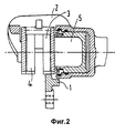
фиг. 2 - разрез изображенного на фиг. 1 дискового тормоза по линии II-II;
фиг. 3 - схема, представляющая принцип изобретения в дисковом тормозе согласно первому варианту исполнения;
фиг. 4 - схема, представляющая принцип изобретения в дисковом тормозе согласно второму варианту исполнения;
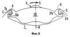
фиг. 5 - схема, представляющая принцип изобретения в дисковом тормозе согласно третьему варианту исполнения;
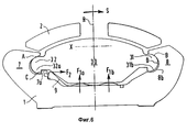
фиг. 6 представляет вариант изображенного на фиг. 3 тормоза;
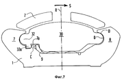
фиг. 7 - другой вариант изображенного на фиг. 3 тормоза.Other characteristics and advantages of the invention will be apparent from the following description, given by way of example and not limited to this, with reference to the accompanying figures, in which:
FIG. 1 is a partial sectional view of a disc brake in accordance with the invention;
FIG. 2 is a sectional view of FIG. 1 disc brake on the line II-II;
FIG. 3 is a diagram showing a principle of the invention in a disc brake according to a first embodiment;
FIG. 4 is a diagram showing a principle of the invention in a disc brake according to a second embodiment;
FIG. 5 is a diagram showing a principle of the invention in a disc brake according to a third embodiment;
FIG. 6 is a variation of FIG. 3 brakes;
FIG. 7 is another embodiment of FIG. 3 brakes.
В общем плане изобретение касается дисковых тормозов с плавающей скобой, предназначенных для оснащения самоходных транспортных средств. In General terms, the invention relates to disc brakes with a floating bracket, designed to equip self-propelled vehicles.
Такие тормоза включают первую опору 1, называемую "обоймой", закрепленную неподвижно относительно транспортного средства, вторую опору 2, выполненную в виде скобы и закрепленную скользящим образом относительно первой, тормозную колодку 3, 4, каждая из которых поддерживается одной из опор, обычно обоймой 1, чтобы оказывать сопротивление приводным усилиям, которые действуют на нее при торможении, и тормозной привод 5, соединенный со второй опорой 2 и приводимый в действие, чтобы вызвать наложение тормозной колодки 3, 4 на диск 6 в соответствии с движением, фактически перпендикулярным диску. Such brakes include a
Каждая тормозная колодка 3, 4 представляет классическим образом центральную зону, такую, как зона 30, и два боковых конца 31, 32, первый 31 из которых выступает по отношению к центральной зоне 30 в направлении вращения S диска 6, а второй 32 представляет по меньшей мере приводной профиль 32a. Each brake pad 3, 4 represents in a classical manner a central zone, such as
Со своей стороны, опора тормозной колодки, например обойма 1, представляет удерживающий профиль 7a, взаимодействующий с приводным профилем 32a тормозной колодки 3, чтобы удерживать последнюю, когда она вовлекается во вращение диска б в направлении S под действием приводных усилий. For its part, the brake shoe support, for example a
Кроме того, первый конец 31 по меньшей мере каждой тормозной колодки, например колодки 3, представляет внешнюю контактную поверхность 31b для упора в соответствующую контактную поверхность 8b, расположенную на элементе 8 опоры 1 тормозной колодки. In addition, the
Согласно изобретению, одна из двух контактных поверхностей 31b, 8b вогнутая, а другая - выпуклая, при этом выпуклая контактная поверхность имеет закругленный профиль. According to the invention, one of the two
Вогнутая контактная поверхность может иметь форму двугранного угла, правильного многоугольника или быть закругленной. The concave contact surface may be in the form of a dihedral angle, a regular polygon, or be rounded.
При отсутствии приводных усилий каждая тормозная колодка прижата к своей опоре под действием упругого усилия F, создаваемого пружиной 9 в нескольких точках, при этом между вогнутой и выпуклой контактными поверхностями 31b, 8b образованы радиальный зазор J и тангенциальный зазор K. In the absence of drive forces, each brake shoe is pressed against its support under the action of the elastic force F created by the
Усилие F включает по меньшей мере одну составляющую F1, направленную вдоль радиуса R диска 6, проходящего через центральную зону трения 30 тормозной колодки, и вторую составляющую F2, перпендикулярную упомянутому радиусу и направленную в направлении S вращения диска 6, в результате чего контактные поверхности прижаты друг к другу в упомянутых точках с неравной нулю опорной реакцией при неработающем тормозе. The force F includes at least one component F1 directed along the radius R of the disk 6 passing through the
Благодаря этим характеристикам контактные поверхности 31b, 8b взаимодействуют друг с другом с неравной нулю опорной реакцией и несмотря на наличие необходимых зазоров. Due to these characteristics, the
Вогнутая поверхность может принимать форму правильного многоугольника и даже, при случае, форму входящего двугранного угла. A concave surface can take the form of a regular polygon and even, if necessary, the shape of an incoming dihedral angle.
Однако предпочтительно, обе контактные поверхности 31b, 8b имеют закругленный профиль, как это показано на фиг. 1 и 3-6, при этом радиус кривизны каждой вогнутой контактной поверхности больше радиуса кривизны соответствующей выпуклой поверхности. However, it is preferred that both
Расположенный на тормозной колодке приводной профиль 32a может принимать форму паза, открывающегося к внешней стороне диска, как показано на фиг. 3 и 4, или форму паза, открывающегося к внешней стороне диска, как показано на фиг. 5. The
Внешняя контактная поверхность 31b тормозной колодки может быть выпуклой (фиг. 3 и 6), или она может представлять вогнутую контактную поверхность (фиг. 4 и 5). Кроме того, первая составляющая F1 упругого усилия является, предпочтительно, центробежной, т.е. повернутой к внутренней стороне диска 6. The
В любом случае желательно, чтобы упругое усилие F, производимое пружиной 9, представляло вторую составляющую F2, перпендикулярную радиусу R диска б, который проходит через центральную зону 30, и направленную по ходу вращения S диска. In any case, it is desirable that the elastic force F produced by the
Пружина 9, расположенная между тормозной колодкой 3 и его опорой 1 (фиг. 1, 3 и 6), может производить распределяющие усилия, как показано на фиг. 6, которая представляет вариант исполнения, в котором составляющие F1 и F2 упругого усилия осуществляются раздельно, при этом первая составляющая F1 сама состоит из двух подсоставляющих F1a и F1b. A
Как показано на фиг. 7, приводной профиль 32a тормозной колодки и каждый удерживающий профиль 7a снабжены дополнительными поверхностями закругленной формы, расположенные друг напротив друга для уменьшения локальных напряжений. As shown in FIG. 7, the brake
Наконец, как показано на фиг. 3 - 5, каждая тормозная колодка может включать внешнюю контактную поверхность 31b, 32b и приводной профиль 31a, 32a на каждом из двух концов 31 и 32, взаимодействующие с внутренними поверхностями 8b, 7b и удерживающими профилями 8a, 7a соответствующих опор 8, 7. Благодаря этим характеристикам тормозная колодка 30 и ее опора 1 (фиг. 3 - 6) соприкасаются друг с другом в точках A, B и C в состоянии покоя тормоза и в точках C и D в случае торможения транспортного средства, достаточно интенсивного, чтобы вызвать максимальную деформацию тормоза, при этом второй конец 32 тормозной колодки 3 оказывается всегда зацепленным в точке C, а первый конец этого башмака находит в любом случае опору на опорной поверхности 1 в точке B, в точке D или же в любой промежуточной точке, расположенной между точками B и D, расположение которых зависит от функциональных зазоров J и K, но присутствие которых не обусловлено параметрами изготовления (допусками) или применения (тепловые расширения, деформации), которым подвергаются эти зазоры. Finally, as shown in FIG. 3 to 5, each brake shoe may include an
Claims (7)
Applications Claiming Priority (3)
| Application Number | Priority Date | Filing Date | Title |
|---|---|---|---|
| FR9304392 | 1993-04-15 | ||
| FR9304392A FR2704034B1 (en) | 1993-04-15 | 1993-04-15 | Disc brake using a sliding shoe pulling pad. |
| PCT/FR1994/000174 WO1994024452A1 (en) | 1993-04-15 | 1994-02-17 | Disk brake using a slidingly abutting drawn pad |
Publications (2)
| Publication Number | Publication Date |
|---|---|
| RU95118884A RU95118884A (en) | 1997-10-20 |
| RU2124657C1 true RU2124657C1 (en) | 1999-01-10 |
Family
ID=9446063
Family Applications (1)
| Application Number | Title | Priority Date | Filing Date |
|---|---|---|---|
| RU95118884A RU2124657C1 (en) | 1993-04-15 | 1994-02-17 | Disk brake |
Country Status (12)
| Country | Link |
|---|---|
| US (1) | US5551537A (en) |
| EP (1) | EP0694131B1 (en) |
| JP (1) | JPH08508813A (en) |
| BR (1) | BR9406159A (en) |
| DE (1) | DE69403649T2 (en) |
| DK (1) | DK0694131T3 (en) |
| ES (1) | ES2105648T3 (en) |
| FR (1) | FR2704034B1 (en) |
| PL (1) | PL173022B1 (en) |
| RU (1) | RU2124657C1 (en) |
| TR (1) | TR28526A (en) |
| WO (1) | WO1994024452A1 (en) |
Families Citing this family (21)
| Publication number | Priority date | Publication date | Assignee | Title |
|---|---|---|---|---|
| FR2735195B1 (en) * | 1995-06-08 | 1998-01-30 | Alliedsignal Europ Services | DISC BRAKE USING A ROTATING LOADED PAD |
| US6259937B1 (en) * | 1997-09-12 | 2001-07-10 | Alfred E. Mann Foundation | Implantable substrate sensor |
| US5915505A (en) * | 1997-09-16 | 1999-06-29 | Chrysler Corporation | Disc brake system with unitary support |
| US5909785A (en) * | 1997-12-10 | 1999-06-08 | Chrysler Corporation | Twin ramp brake pad reaction member |
| FR2774733B1 (en) * | 1998-02-12 | 2000-04-21 | Bosch Syst Freinage | DISC BRAKE WITH BALANCED REACTION |
| FR2776352B1 (en) * | 1998-03-23 | 2000-05-19 | Bosch Syst Freinage | DISC BRAKE DAMPED BY SHEAR |
| US6039155A (en) * | 1998-03-27 | 2000-03-21 | Robert Bosch Technology Corporation | Disc brake |
| JP2001304311A (en) * | 2000-04-27 | 2001-10-31 | Akebono Brake Ind Co Ltd | Floating caliper type disc brake |
| DE10108973A1 (en) * | 2001-02-24 | 2002-09-05 | Bosch Gmbh Robert | Brake pad holder for a disc brake |
| US7128809B2 (en) * | 2002-11-05 | 2006-10-31 | The Procter & Gamble Company | High caliper web and web-making belt for producing the same |
| US6755233B2 (en) | 2002-11-05 | 2004-06-29 | Haldex Brake Corporation | Method and apparatus for positioning an end of a push rod of a brake actuator |
| JP2004353815A (en) * | 2003-05-30 | 2004-12-16 | Advics:Kk | Disk brake |
| US20050023090A1 (en) * | 2003-07-30 | 2005-02-03 | Mackiewicz John Edmund | Disc brake |
| US6782977B1 (en) | 2003-09-23 | 2004-08-31 | Robert Bosch Corporation | Disc brake |
| GB0422909D0 (en) * | 2004-10-15 | 2004-11-17 | Delphi Tech Inc | Brake pad |
| DE102005015774A1 (en) * | 2004-10-26 | 2006-05-04 | Knorr-Bremse Systeme für Nutzfahrzeuge GmbH | Disc brake, in particular for a commercial vehicle |
| US6991074B1 (en) | 2005-02-17 | 2006-01-31 | Robert Bosch Gmbh | Disc Brake |
| US20070119665A1 (en) * | 2005-11-28 | 2007-05-31 | Manuel Barbosa | Outer pad abutment design for frame type calipers |
| US20070151814A1 (en) * | 2006-01-05 | 2007-07-05 | Xavier Delayre | Multi-disc brake with fixed center brake pad assembly |
| US9328785B2 (en) * | 2013-03-15 | 2016-05-03 | Hb Performance Systems, Inc. | Tensioned brake pad |
| US20150267763A1 (en) * | 2014-03-20 | 2015-09-24 | Akebono Brake Industry Co., Ltd. | Brake torque abutment |
Family Cites Families (12)
| Publication number | Priority date | Publication date | Assignee | Title |
|---|---|---|---|---|
| JPS5211374A (en) * | 1975-07-17 | 1977-01-28 | Tokico Ltd | Disc brake |
| BE835306A (en) * | 1975-11-06 | 1976-03-01 | DISC BRAKE | |
| FR2410178A1 (en) * | 1977-11-29 | 1979-06-22 | Dba | DISC BRAKE |
| DE2804808B2 (en) * | 1978-02-04 | 1981-04-16 | Alfred Teves Gmbh, 6000 Frankfurt | Brake shoe holder for a partially lined disc brake, in particular for motor vehicles |
| DE2838921C2 (en) * | 1978-09-07 | 1986-09-04 | Alfred Teves Gmbh, 6000 Frankfurt | Floating caliper disc brake |
| DE2926818A1 (en) * | 1979-07-03 | 1981-03-12 | Alfred Teves Gmbh, 6000 Frankfurt | PARTIAL DISC BRAKE. |
| FR2478761A1 (en) * | 1980-03-18 | 1981-09-25 | Dba | DISC BRAKE |
| GB8828231D0 (en) * | 1988-01-07 | 1989-01-05 | Teves Gmbh Alfred | Spot-type disc brake |
| FR2635842B1 (en) * | 1988-08-29 | 1990-10-19 | Bendix France | DISC BRAKE SPRING AND DISC BRAKE COMPRISING SAME |
| DE3815733A1 (en) * | 1988-05-07 | 1989-11-16 | Teves Gmbh Alfred | PARTIAL PAD DISC BRAKE |
| FR2638498B1 (en) * | 1988-10-28 | 1993-04-09 | Bendix France | BRAKE WITH TWO FIXED GAP DISCS |
| DE4027563A1 (en) * | 1990-08-31 | 1992-03-05 | Teves Gmbh Alfred | FLOATING SADDLE AND BRAKE PAD FOR PARTIAL DISC BRAKES |
-
1993
- 1993-04-15 FR FR9304392A patent/FR2704034B1/en not_active Expired - Fee Related
-
1994
- 1994-02-17 ES ES94907585T patent/ES2105648T3/en not_active Expired - Lifetime
- 1994-02-17 DK DK94907585.7T patent/DK0694131T3/en active
- 1994-02-17 DE DE69403649T patent/DE69403649T2/en not_active Expired - Fee Related
- 1994-02-17 BR BR9406159A patent/BR9406159A/en not_active IP Right Cessation
- 1994-02-17 EP EP94907585A patent/EP0694131B1/en not_active Expired - Lifetime
- 1994-02-17 PL PL94311120A patent/PL173022B1/en unknown
- 1994-02-17 WO PCT/FR1994/000174 patent/WO1994024452A1/en active IP Right Grant
- 1994-02-17 RU RU95118884A patent/RU2124657C1/en not_active IP Right Cessation
- 1994-02-17 JP JP6522809A patent/JPH08508813A/en not_active Ceased
- 1994-02-17 US US08/204,248 patent/US5551537A/en not_active Expired - Lifetime
- 1994-04-04 TR TR00289/94A patent/TR28526A/en unknown
Also Published As
| Publication number | Publication date |
|---|---|
| JPH08508813A (en) | 1996-09-17 |
| PL311120A1 (en) | 1996-02-05 |
| DE69403649T2 (en) | 1997-11-13 |
| EP0694131B1 (en) | 1997-06-04 |
| US5551537A (en) | 1996-09-03 |
| EP0694131A1 (en) | 1996-01-31 |
| FR2704034B1 (en) | 1995-05-19 |
| PL173022B1 (en) | 1998-01-30 |
| DK0694131T3 (en) | 1997-12-22 |
| ES2105648T3 (en) | 1997-10-16 |
| TR28526A (en) | 1996-10-01 |
| DE69403649D1 (en) | 1997-07-10 |
| BR9406159A (en) | 1996-01-02 |
| WO1994024452A1 (en) | 1994-10-27 |
| FR2704034A1 (en) | 1994-10-21 |
Similar Documents
| Publication | Publication Date | Title |
|---|---|---|
| RU2124657C1 (en) | Disk brake | |
| EP0710778B1 (en) | Disc brake | |
| US6296085B1 (en) | Disk brake | |
| US5125482A (en) | Disc brake elastic pressing members having unequal pressing forces | |
| US9897152B2 (en) | Wear optimized pad design | |
| RU2123626C1 (en) | Disk brake for automobile | |
| RU95118884A (en) | DISK BRAKE | |
| KR100477779B1 (en) | Disk brake and brake shoe set for a disk brake | |
| JPH0389033A (en) | Disc brake | |
| JP4698147B2 (en) | Disc brake assembly | |
| RU95118886A (en) | DISC BRAKE FOR CAR | |
| US4915198A (en) | Friction pad support mechanism for disc brake | |
| US4013147A (en) | Segmented friction disc for brakes | |
| US4969540A (en) | Center loop anti-rattle spring | |
| US3460652A (en) | Anti-noise disk brake | |
| US4027751A (en) | Noise-reducing spring for a disc brake | |
| WO2008079087A1 (en) | Method and device for disc brakes and vehicle | |
| US9976610B2 (en) | Wear optimized pad design | |
| JP3700064B2 (en) | Disc brake | |
| US6206146B1 (en) | Disc brake assembly | |
| JP2649933B2 (en) | Disc brake friction pad support mechanism | |
| US5915505A (en) | Disc brake system with unitary support | |
| JPH07103268A (en) | Disk brake device | |
| JPH01224532A (en) | Supporting mechanism for friction pad of disc brake | |
| CA1295954C (en) | Friction pad support mechanism for disc brake |
Legal Events
| Date | Code | Title | Description |
|---|---|---|---|
| MM4A | The patent is invalid due to non-payment of fees |
Effective date: 20110218 |