RU2115137C1 - Range-finding method of location and components of vector of velocity of objects by radio signals of spacecraft of satellite radio navigation systems - Google Patents
Range-finding method of location and components of vector of velocity of objects by radio signals of spacecraft of satellite radio navigation systems Download PDFInfo
- Publication number
- RU2115137C1 RU2115137C1 RU94018148A RU94018148A RU2115137C1 RU 2115137 C1 RU2115137 C1 RU 2115137C1 RU 94018148 A RU94018148 A RU 94018148A RU 94018148 A RU94018148 A RU 94018148A RU 2115137 C1 RU2115137 C1 RU 2115137C1
- Authority
- RU
- Russia
- Prior art keywords
- ranges
- differences
- range
- navigation
- satellite
- Prior art date
Links
Images


Landscapes
- Position Fixing By Use Of Radio Waves (AREA)
Abstract
Description
Изобретение относится к области космической радионавигации, геодезии и может быть использовано для определения координат местоположения и составляющих вектора скорости объектов. The invention relates to the field of space radio navigation, geodesy and can be used to determine location coordinates and components of the velocity vector of objects.
Известен доплеровский разностно-дальномерный способ определения координат местоположения и составляющих вектора скорости объектов по навигационным радиосигналам космических аппаратов (КА) спутниковых радионавигационных систем (СРНС), основанный на измерениях разностей топоцентрических расстояний между объектом и двумя положениями одного и того же навигационного КА (НКА) в последовательные моменты времени (П.С. Волосов, Ю.С. Дубенко и др. Судовые комплексы спутниковой навигации. Л.: Судостроение, 1976). The known Doppler difference-ranging method for determining the coordinates of the location and components of the velocity vector of objects from the navigation radio signals of spacecraft (SC) of satellite radio navigation systems (SRNS), based on measurements of the differences of topocentric distances between the object and two positions of the same navigation spacecraft (NSC) in successive moments of time (P.S. Volosov, Yu.S. Dubenko and others. Ship complexes of satellite navigation. L .: Sudostroenie, 1976).
Практической реализацией известного способа являются российская СРНС "Цикада" и американская СРНС "Транзит" - навигационные системы первого поколения. В нем интегрирование доплеровского смещения частоты принятых за интервал времени ΔT от навигационного искусственного спутника Земли (НИСЗ) радиосигналов позволяет определить число длин волн, укладывающихся в разность расстояний от фазового центра антенны приемного устройства объекта до двух положений НИСЗ (двух положений фазового центра антенны НИСЗ):

где
t1 и t2 - время передачи временных меток НИСЗ;
R1(t1) и R2(t2) - расстояния между фазовыми центрами антенн объекта и НИСЗ;
c - скорость света;
fп - частота принимаемого сигнала;
fо - частота опорного сигнала,
fп= fи±Δfи+Δfио+Δfтр+Δfгр+Δfдр,
где
fи - частота сигнала, излучаемого НИСЗ;
±Δfи - нестабильность частоты излучаемого сигнала;
Δfио,Δfтр - неизвестные сдвиги частоты, обусловленные распространением сигналов в ионосфере, тропосфере;
Δfгр - неизвестный сдвиг частоты, обусловленный гравитационными силами;
Δfдр - неизвестные сдвиги частоты, обусловленные другими факторами,
fo= fи±Δf+Δfo, ,
где
Δfo - известный постоянный сдвиг частоты (частотная подставка);
±Δf - нестабильность частоты опорного сигнала.The practical implementation of the known method is the Russian SRNS "Cicada" and the American SRNS "Transit" - navigation systems of the first generation. In it, integration of the Doppler frequency offset of the radio signals received over the time interval ΔT from the navigation artificial satellite of the Earth (NESA) allows us to determine the number of wavelengths that fit into the difference in distance from the phase center of the antenna of the receiving device of the object to two positions of the NISS (two positions of the phase center of the NISS antenna):
Where
t 1 and t 2 - the transmission time of the time stamps of the NLHA;
R 1 (t 1 ) and R 2 (t 2 ) - the distance between the phase centers of the antennas of the object and the NHA;
c is the speed of light;
f p - frequency of the received signal;
f about the frequency of the reference signal
f p = f and ± Δf and + Δf io + Δf tr + Δf gr + Δf dr ,
Where
f and - the frequency of the signal emitted by the NHA;
± Δf and - instability of the frequency of the emitted signal;
Δf io , Δf tr - unknown frequency shifts due to the propagation of signals in the ionosphere, troposphere;
Δf gr - unknown frequency shift due to gravitational forces;
Δf dr - unknown frequency shifts due to other factors,
f o = f and ± Δf + Δf o ,,
Where
Δf o - known constant frequency shift (frequency stand);
± Δf is the instability of the frequency of the reference signal.
С учетом изложенного выражение примет вид

Из выражения видно, что интегральный доплеровский сдвиг частоты определяется двумя слагаемыми. Первое слагаемое - погрешности измерений, обусловленные условиями распространения радиоволн, гравитационным полем Земли, нестабильностью частоты излучения опорного генератора и другими факторами. Они войдут в навигационное уравнение как неизвестные. Второе слагаемое является прямым измерением изменения наклонной дальности в длинах волн опорной частоты определяющегося объекта.Based on the foregoing, the expression will take the form
It can be seen from the expression that the integral Doppler frequency shift is determined by two terms. The first term is the measurement error due to the propagation conditions of the radio waves, the Earth's gravitational field, the instability of the radiation frequency of the reference generator and other factors. They will enter the navigation equation as unknowns. The second term is a direct measurement of the change in the slant range in the wavelengths of the reference frequency of the determined object.
Ошибка сложения системы слежения за несущей (ССР), которая отсутствует в рассмотренном навигационном уравнении, также входит в ошибку измерения радионавигационного параметра (РНП). Отслеживаемая функция времени - несущая частоты имеет ненулевые производные высокого порядка. Следовательно, помимо случайных ошибок (шумовых) реальный следящий контур с астатизмом конечного порядка будет иметь динамические ошибки, обусловленные наличием производных входного воздействия более высокого порядка, чем порядок астатизма системы. Уменьшение случайной ошибки системы фазовой автоподстройки частоты (ФАПЧ) ССН требует применения более инерционного контура обратной связи (сужение полосы пропускания фильтра низкой частоты), но при этом возрастают динамические ошибки ССР и наоборот. The addition error of the carrier tracking system (SSR), which is absent in the considered navigation equation, is also included in the measurement error of the radio navigation parameter (RNP). Tracked function of time - the carrier frequency has non-zero derivatives of high order. Therefore, in addition to random errors (noise), a real tracking circuit with finite-order astatism will have dynamic errors due to the presence of derivatives of the input action of a higher order than the system astatism order. Reducing the random error of the phase-locked loop (PLL) SSN requires the use of a more inertial feedback loop (narrowing the passband of the low-pass filter), but the dynamic errors of the SSR increase and vice versa.
Выражая дальности через координаты прямоугольной геоцентрической системы координат, навигационное уравнение примет вид

где
x1, y1, z1, x2, y2, z2 - координаты фазового центра антенны спутника в моменты времени t2 и t1 соответственно;
x0, y0, z0 -неизвестные координаты фазового центра антенны определяющегося объекта.Expressing the distance through the coordinates of a rectangular geocentric coordinate system, the navigation equation takes the form
Where
x 1 , y 1 , z 1 , x 2 , y 2 , z 2 are the coordinates of the phase center of the satellite antenna at time t 2 and t 1, respectively;
x 0 , y 0 , z 0 are the unknown coordinates of the phase center of the antenna of the detected object.
Как видно, три измерения разностей дальностей в четырех последовательных положениях спутника на орбите позволяют определить координаты объекта x0, y0, z0. В процессе измерений необходимо ждать, пока дальность до НИСЗ изменится на достаточную величину.As you can see, three measurements of the differences of ranges in four consecutive positions of the satellite in orbit make it possible to determine the coordinates of the object x 0 , y 0 , z 0 . In the process of measurement, it is necessary to wait until the range to the NLHA changes by a sufficient amount.
Разностно-дальномерный способ проявляет свои достоинства на таких расстояниях (базах) между положениями НИСЗ на орбите, когда они соизмеримы с расстояниями между НКА и определяющимся объектом. The difference-rangefinder method shows its advantages at such distances (bases) between the positions of the NLHA in orbit when they are comparable with the distances between the spacecraft and the determined object.
В соответствии с изложенным недостатками известного способа являются
ошибки, обусловленные ССР;
ошибки за счет нестабильности частоты излучения НКА и опорного генератора;
ошибки, обусловленные условиями распространения радиоволн в ионосфере, тропосфере и другими факторами;
систематические и случайные ошибки;
низкая точность определения координат местоположения и составляющих вектора скорости объектов при использовании НИСЗ на средневысоких и высоких орбитах.In accordance with the above disadvantages of the known method are
errors due to SSR;
errors due to the instability of the radiation frequency of the spacecraft and the reference generator;
errors due to propagation conditions in the ionosphere, troposphere and other factors;
systematic and random errors;
low accuracy in determining the coordinates of the location and components of the velocity vector of objects when using the NISS in medium-high and high orbits.
Известен также дальномерный способ, который принят в качестве прототипа. Практической реализацией этого способа являются СРНС второго поколения - российская Global Orbiting Navigation Sattellite System (ГЛОНАСС) и американская Global Positioning System (GPS). Геометрическим эквивалентом конечного алгоритма этого способа решения навигационной задачи является построение относительно используемых навигационных искусственных спутников Земли (НИСЗ) совокупности поверхностей положения, точка пересечения которых и является искомым положением объекта (Бортовые устройства спутниковой радионавигации. /Под ред. В.С. Шебшаевича. М.: Транспорт, 1988). A rangefinder method is also known, which is adopted as a prototype. The practical implementation of this method is the second generation SRNS - the Russian Global Orbiting Navigation Sattellite System (GLONASS) and the American Global Positioning System (GPS). The geometric equivalent of the final algorithm for this method of solving the navigation problem is the construction of a set of position surfaces with respect to the used navigation artificial earth satellites (NISS), the intersection point of which is the desired position of the object (Airborne devices of satellite radio navigation. / Ed. By V.S.Shebshaevich. M. : Transport, 1988).
Для решения навигационной задачи минимально необходимый объем функциональных зависимостей должен быть равен числу оцениваемых параметров. Определение координат местоположения объекта сводится к решению системы уравнений

где
R1, . . . , R4 - результаты измерений наклонных дальностей, полученные с помощью следящей системы за задержкой (ССЗ);
x, y, z - координаты объекта в геометрической прямоугольной системе координат;
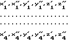
x1, y1, z1 .... x4, y4, z4 - координаты четырех путников, передаваемые в навигационном сообщении;
ΔRт - разница между истинной дальностью объекта-спутника и измеренной, обусловленной сдвигом шкалы времени объекта относительно шкалы времени НИСЗ;
ΔR1,...,ΔR4 - погрешности измерений, обусловленные атмосферой, ионосферой, другими факторами.To solve the navigation problem, the minimum required amount of functional dependencies should be equal to the number of estimated parameters. Determining the coordinates of the location of an object is reduced to solving a system of equations
Where
R 1 ,. . . , R 4 - slant range measurements obtained using a delay tracking system (CVD);
x, y, z - coordinates of the object in a geometric rectangular coordinate system;
x 1 , y 1 , z 1 .... x 4 , y 4 , z 4 are the coordinates of the four travelers transmitted in the navigation message;
ΔR t is the difference between the true range of the satellite object and the measured, due to the shift of the object’s time scale relative to the NISS time scale;
ΔR 1 , ..., ΔR 4 - measurement errors due to the atmosphere, ionosphere, and other factors.
Для определения координат местоположения объекта необходимо, чтобы в поле зрения объекта находились одновременно четыре спутника. В результате решения этой системы уравнений определяются четыре известные: три координаты местоположения объекта (x, y, z) и поправка ΔRт к его шкале времени (поправка к часам).To determine the coordinates of the location of the object, it is necessary that four satellites are simultaneously in the field of view of the object. As a result of solving this system of equations, four known are determined: three coordinates of the object’s location (x, y, z) and correction ΔR t to its time scale (correction to hours).
Аналогичным образом, с использованием результатов измерений с помощью ССН, определяются три составляющие вектора скорости ![]()
![]()

где
![]()
![]()

![]()
![]()
![]()
![]()
Where
![]()
![]()
![]()
![]()
Измерение дальности в аппаратуре объекта осуществляется путем измерения временного интервала между временными отметками принимаемого от спутника кода и местного кода объекта. The range measurement in the equipment of the object is carried out by measuring the time interval between the time stamps of the code received from the satellite and the local code of the object.
Эффективность данного метода определяется в основном шумовой погрешностью измерения РНП, поскольку именно шумовая погрешность ограничивает эффект компенсации сильнокоррелированных погрешностей. Для оценки шумовой погрешности используется (Бортовые устройства спутниковой радионавигации. /Под ред. В.С. Шебшаевича. М.: Транспорт, 1988) выражение

где
ε
Δ - длительность элемента дальномерного кода;
c/N0 - отношение мощности сигнала к спектральной плотности мощности шума на входе приемника;
ΔBССЗ - односторонняя ширина полосы ССЗ;
ΔBПЧ - односторонняя ширина полосы УПЧ дискриминатора;
K1, K2 - постоянные параметры, зависящие от выбранного технического решения.The effectiveness of this method is mainly determined by the noise error of the measurement of RNP, since it is the noise error that limits the effect of compensation for highly correlated errors. To assess the noise error is used (On-board devices of satellite radio navigation. / Under the editorship of VS Shebshaevich. M .: Transport, 1988) expression
Where
ε
Δ is the duration of the element of the ranging code;
c / N 0 is the ratio of signal power to spectral density of noise power at the input of the receiver;
ΔB CVD - one-sided bandwidth of the CVD;
ΔB IF - one-way bandwidth of the IF amplifier;
K 1 , K 2 - constant parameters, depending on the selected technical solution.
Измерение доплеровского сдвига частоты основано на измерении приращения дальности на частоте несущей с использованием ССН. The measurement of the Doppler frequency shift is based on measuring the range increment at the carrier frequency using CCH.
Оценка точности измерения приращения дальности определяется выражением для дисперсии фазы ε

где
λ - длина волны несущей;
BССН - ширина полосы схемы слежения за несущей.The estimation of the accuracy of measuring the increment of range is determined by the expression for the phase dispersion ε
Where
λ is the carrier wavelength;
B CCH is the bandwidth of the carrier tracking circuit.
Шумовая погрешность измерений приращений дальностей на частоте несущей практически на порядок меньше шумовой погрешности измерений дальностей с использованием дальномерных кодов. The noise error of measuring increments of ranges at the carrier frequency is almost an order of magnitude smaller than the noise error of measurements of ranges using rangefinding codes.
Дальномерный способ не позволяет, например, из-за различий в СРНС ГЛОНАСС и GPS совместно их использовать. The rangefinder method does not allow, for example, due to differences in the GLONASS and GPS ARNS to share them.
Таким образом, недостатками известного способа, прототипа, являются
ошибки следящей системы за задержкой от отношения сигнал/шум;
ошибки следящей системы за несущей от отношения сигнал/шум;
ошибки, обусловленные условиями распространения радиоволн в ионосфере, тропосфере и другими факторами;
ошибки, обусловленные сдвигом шкалы времени объекта относительно шкал времени НИСЗ за счет нестабильности частот генераторов спутников и опорного генератора объекта;
невозможность совместного использования источников радиоизлучений систем различного назначения.Thus, the disadvantages of the known method, prototype, are
errors of the tracking system for the delay from the signal-to-noise ratio;
carrier tracking errors from the signal-to-noise ratio;
errors due to propagation conditions in the ionosphere, troposphere and other factors;
errors caused by the shift of the object’s time scale relative to the NIEW time scales due to the instability of the frequencies of the satellite generators and the reference generator of the object;
the impossibility of sharing sources of radio emission systems for various purposes.
Для устранения ионосферной задержки в известных способах используется аппаратурная компенсация с помощью двухчастотных измерений и компенсация с помощью поправок, рассчитываемых по априорным данным. To eliminate the ionospheric delay in the known methods, apparatus compensation using two-frequency measurements and compensation using corrections calculated using a priori data are used.
Известный способ (прототип) характеризуется следующей совокупностью действий над принимаемыми спутниковыми радионавигационными сигналами:
прием N-канальным приемным устройством двухчастотных радиосигналов N НИСЗ;
определение дальностей от объекта до каждого спутника путем измерения временных сдвигов кодовых последовательностей, формируемых генераторами спутников относительно кодовой последовательности, формируемой генератором объекта;
измерение приращений дальностей путем измерения приращений фаз несущих;
определение координат местоположения объекта;
определение составляющих вектора скорости объекта.The known method (prototype) is characterized by the following set of actions on received satellite radio navigation signals:
the reception by the N-channel receiver of two-frequency radio signals N NLH;
determining the distances from the object to each satellite by measuring the time shifts of the code sequences generated by the satellite generators relative to the code sequence generated by the object generator;
measuring increments of ranges by measuring increments of the phases of the carriers;
determination of the coordinates of the location of the object;
determination of the components of the velocity vector of the object.
Целью изобретения является повышение точности определения координат местоположения, составляющих вектора скорости определяющегося объекта по навигационным радиосигналам КА СРНС и с использованием радиосигналов наземных воздушных источников радиоизлучений, а также с использованием радиоизлучений КА других систем и их имитаторов. The aim of the invention is to improve the accuracy of determining the coordinates of the location of the components of the velocity vector of the determined object from the navigation radio signals of the SRNS spacecraft and using the radio signals of ground-based air sources of radio emissions, as well as using the radio emissions of the spacecraft of other systems and their simulators.
Цель достигается тем, что по предлагаемому способу в N-канальном приемном устройстве, один из которых является ведущим, а другие - ведомыми каналами, производят определение разности дальностей между дальностями, измеренными ведомыми приемными устройствами, и дальностью, измеренной ведущим приемным устройством, а также определение разностей скоростей изменения дальностей между скоростями изменения дальностей, вычисленными по измерениям доплеровских сдвигов частоты ведомыми приемными устройствами, и скоростью изменения дальности, вычисленной по измерению доплеровского сдвига частоты ведущим приемным устройством, затем производят определение двойных разностей дальностей и двойных разностей скоростей изменения дальностей путем взаимного вычитания друг из друга разностей дальностей и разностей скоростей изменения дальностей. The goal is achieved by the fact that according to the proposed method, in the N-channel receiving device, one of which is the master, and the other by the slave channels, the distance difference between the ranges measured by the slave receiving devices and the range measured by the master receiving device is determined, as well as the determination the differences in the rates of change of ranges between the rates of change of ranges calculated from measurements of Doppler frequency shifts by slave receiving devices and the rate of change of range, techniques, are to measure the Doppler frequency shift of the leading receiving device, then a determination is made of double-difference and double difference ranges rates of change of distances by mutual subtraction from each other by difference distances and range rate difference.
Дополнительными отличиями предлагаемого способа являются следующие. Additional differences of the proposed method are as follows.
Ведущим и приемным устройствами определение разностей дальностей производят между объектом и двумя положениями спутников, определяемыми мерным интервалом путем измерения приращений фаз несущих с использованием фазовых автоподстроек частот систем слежения за несущими навигационных радиосигналов спутников. The leading and receiving devices determine the difference in ranges between the object and the two positions of the satellites, determined by the measured interval by measuring the increments of the phases of the carriers using phase-locked loop frequency tracking systems tracking the navigation radio signals of the satellites.
Определение двойных разностей дальностей производят между объектом и двумя положениями спутников, определяемыми мерным интервалом, путем измерения разностей частот Доплера, принятых приемными устройствами с использованием квадратурных фазовых детекторов, умножив их средние значения на мерный интервал. The determination of double range differences is made between the object and the two positions of the satellites, determined by the measured interval, by measuring the differences of the Doppler frequencies received by the receiving devices using quadrature phase detectors, multiplying their average values by the measured interval.
Приемное устройство ведущего канала принимает сигналы имитатора спутниковых сигналов. The receiver of the master channel receives signals of a satellite signal simulator.
Выделение сигналов с частотами Доплера производят путем возведения принимаемых сигналов в квадрат с последующим возвратом частот на искомые с использованием делителей частот. The selection of signals with Doppler frequencies is carried out by squaring the received signals into a square with the subsequent return of the frequencies to the desired using frequency dividers.
Геометрическая интерпретация предлагаемого способа поясняется на примере созвездия четырех КА ГЛОНАСС и одного КА GPS, фиг. 1. The geometric interpretation of the proposed method is illustrated by the example of a constellation of four GLONASS spacecraft and one GPS satellite, FIG. one.
Принимаемый приемным устройством навигационный радиосигнал КА GPS является ведущим сигналом, а канал приема приемным устройством сигналов КА ГЛОНАСС - ведомым. Соответственно навигационные сигналы КА ГЛОНАСС, приемное устройство КА являются ведомыми. The GPS satellite navigation radio signal received by the receiver is the master signal, and the receiving channel of the GLONASS satellite signals receiver is the slave. Accordingly, the navigation signals of the GLONASS spacecraft, the spacecraft receiving device are slaves.
В соответствии с вышеизложенным
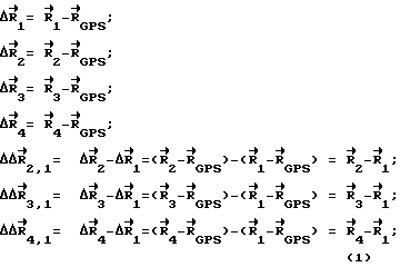
где

![]()
Where
![]()
Геометрическая интерпретация определения координат и составляющих вектора скорости по разностям приращений дальностей и двойных разностям приращений, измеренных с использованием приращений фаз несущих, поясняется на примере двух КА: ведущего КА и одного ведомого КА ГЛОНАСС, фиг. 2. The geometric interpretation of the determination of the coordinates and components of the velocity vector from the differences in the increments of ranges and the double differences of the increments measured using the increments of the phases of the carriers is illustrated by the example of two spacecraft: the leading spacecraft and one slave spacecraft GLONASS, Fig. 2.
Точками t1, t*, t2 обозначены положения НИСЗ на орбите, являющиеся границами отсчетов навигационного параметра (мерный интервал).Points t 1 , t * , t 2 denote the position of the NLHA in orbit, which are the boundaries of the readings of the navigation parameter (measured interval).
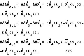
Разности приращений дальностей запишутся следующим образом соответственно:

Двойные разности приращений дальностей примут вид
Разности дальностей в квадратных скобках системы уравнений (1) проявляют свои достоинства, как это было показано выше на таких расстояниях (базах) между положениями НИСЗ на орбите, когда они соизмеримы с расстоянием между НКА и определяющимся объектом. В нашем примере базы незначительны. Для выполнения этого условия систему уравнений (2) преобразуют в тождественную систему уравнений, у которой данное условие выполняется:

Таким образом, из системы разностей дальностей для орбит НКА с тождественными параметрами орбит для созвездия из 5 НКА один GPS - ведущий, четыре ГЛОНАСС - ведомые.Differences in increments of ranges are written as follows, respectively:
Double differences of increments of ranges will take the form
The range differences in square brackets of the system of equations (1) show their advantages, as was shown above at such distances (bases) between the positions of the NESA in orbit when they are commensurate with the distance between the spacecraft and the determined object. In our example, the bases are negligible. To fulfill this condition, the system of equations (2) is transformed into an identical system of equations for which this condition is satisfied:
Thus, from the system of range differences for the orbits of the spacecraft with identical orbital parameters for the constellation of 5 spacecraft, one GPS is the master, four GLONASS are the followers.
Окончательные системы уравнений для двойных разностей дальностей (1) и для двойных разностей приращений дальностей (3), выраженные через координаты в геометрической прямоугольной системе координат, примут вид
для двойных разностей дальностей

Для двойных разностей приращений дальностей


где
for double range differences
For double range increment differences
Where
Аналогично с использованием результатов измерений с помощью ССН определяются составляющие вектора скорости:


где

Where
Анализируя системы навигационных уравнений двойных разностей дальностей (4), двойных разностей приращений дальностей (5) и скоростей (6) с использованием ведущего, ведомых радиосигналов НИСЗ и соответствующих приемных устройств, каналов, видим, что в уравнениях компенсируются координаты ведущего НИСЗ GPS, компенсируются также погрешности, обусловленные расхождением шкал времени и частот GPS, ГЛОНАСС относительно шкалы времени, частоты объекта. Analyzing the systems of navigation equations of double range differences (4), double differences of range increments (5) and speeds (6) using the master, slave radio signals of the NISS and the corresponding receiving devices, channels, we see that the coordinates of the master NISS GPS are compensated in the equations, they are also compensated errors due to the discrepancy between the time scales and GPS, GLONASS frequencies relative to the time scale, object frequency.
Если в навигационных уравнениях известного способа присутствуют погрешности, обусловленные ионосферой, тропосферой, то в уравнениях предлагаемого способа с использованием двойных разностей дальностей присутствуют их разности. If in the navigation equations of the known method there are errors due to the ionosphere, troposphere, then in the equations of the proposed method using double range differences, their differences are present.
Для обеспечения высокой точности решения навигационной задачи, обусловленной геометрическим фактором определения положения в пространстве, положение КА в пространстве выбирается таким, при котором один КА находится в зените (обеспечивая высокую точности определения положения по вертикали), а остальные КА - в горизонтальной плоскости в направлениях, отличающихся друг от друга на 120 - 180o (обеспечивая высокую точность определения положения по горизонтали) в зависимости от количества используемых КА.To ensure high accuracy in solving the navigation problem due to the geometrical factor of determining the position in space, the position of the spacecraft in space is chosen such that one spacecraft is at its zenith (providing high accuracy in determining the vertical position), and the rest of the spacecraft are in the horizontal plane in the directions differing from each other by 120 - 180 o (providing high accuracy of determining the horizontal position) depending on the number of used spacecraft.
Таким образом, предлагаемый способ, несмотря, например, на серьезные различия в ГЛОНАСС и GPS, в способах задания эфемерид, в компоновке суперкадров и структур кадров служебной информации, в неидентичности используемых систем отсчета пространственных координат и различии шкал времени, формируемые от различных эталонов частоты и времени, позволяет совместное их использование, не проводя их в требуемое соответствие, т.е. без всяких организационных материальных доработок и доработок математического обеспечения систем. Thus, the proposed method, despite, for example, serious differences in GLONASS and GPS, in the methods for setting the ephemeris, in the arrangement of superframes and frame structures of service information, in the non-identity of the reference systems of spatial coordinates and the difference in time scales generated from different frequency standards and time, allows their joint use, without putting them into the required correspondence, i.e. without any organizational material modifications and improvements to the mathematical support of systems.
Принимая радионавигационные сигналы КА ГЛОНАСС и GPS параллельно или последовательно, используя мультиплексное приемное устройство или многоканальное, а также беря в одной серии измерений в качестве ведущих КА GPS, а в качестве ведомого КА ГЛОНАСС и наоборот в другой серии, можно определить координаты и составляющие вектора скорости объекта как в координатно-временной системе GPS, так и в координатно-временной системе ГЛОНАСС, не приводя их в соответствие. By receiving the GLONASS and GPS spacecraft navigation signals in parallel or sequentially, using a multiplex receiver or multichannel, and taking GPS as the master spacecraft in one series, and as a slave GLONASS spacecraft and vice versa in another series, it is possible to determine the coordinates and components of the velocity vector object both in the coordinate-time system GPS, and in the coordinate-time system GLONASS, without bringing them into line.
Совместное использование систем обеспечит определенную универсальность навигационных определений, надежность и достоверную обсервацию за счет сравнения результатов определений по разным системам для выявления случаев нарушения функционирования одной из систем. Joint use of systems will provide a certain universality of navigation definitions, reliability and reliable observation by comparing the results of definitions for different systems to identify cases of malfunctioning of one of the systems.
Под надежностью навигационного обеспечения понимается способность навигационной системы в любой момент времени обеспечить объект информацией для определения местоположения с точностью, гарантированной для рабочей зоны. Reliability of navigation support is understood as the ability of the navigation system at any time to provide the object with information for determining the location with an accuracy guaranteed for the working area.
Под достоверностью понимается способность навигационной системы выявлять отклонения в своем функционировании, приводящие к ухудшению точности определения координат и составляющих вектора скорости объекта за пределы заданных допустимых значений. Reliability is understood as the ability of the navigation system to detect deviations in its functioning, leading to a deterioration in the accuracy of determining the coordinates and components of the velocity vector of the object beyond the specified acceptable values.
Если система навигационных уравнений двойных разностей предлагаемого способа с использованием измерений с помощью дальномерных кодов (1) является по сути системой уравнений разностей дальностей, то система навигационных уравнений двойных разностей приращений дальностей, измеренных с помощью приращений фаз несущих на мерном интервале (2), является системой уравнений двойных разностей дальностей и также позволяет решить навигационную задачу - определить координаты местоположения и составляющие вектора скорости объекта. Поскольку, как это было показано выше, точность измерений двойных разностей приращений фаз на несущих частотах на порядок выше точности измерений разностей временных сдвигов кодовых последовательностей, то и точность решения навигационной задачи с использованием приращений фаз также выше точности решения с использованием разностей дальностей. If the system of navigation equations of double differences of the proposed method using measurements using range-finding codes (1) is essentially a system of equations of range differences, then the system of navigation equations of double differences of range increments, measured using phase increments of the carriers on the measuring interval (2), is a system equations of double range differences and also allows you to solve the navigation problem - to determine the coordinates of the location and the components of the velocity vector of the object. Since, as was shown above, the accuracy of measurements of double differences of phase increments at carrier frequencies is an order of magnitude higher than the accuracy of measurements of differences in time shifts of code sequences, the accuracy of solving a navigation problem using phase increments is also higher than the accuracy of solutions using range differences.
В целях дальнейшего повышения точности решения навигационной задачи с использованием приращений фаз на несущих частотах за счет исключений из измерений погрешности, обусловленной ССН, двойные разности приращений дальностей производятся путем выделения из принятых сигналов с частотами, равными разностям частот Доплера, с использованием квадратурных фазовых детекторов, на первые выходы которых поступают сигнал ведущего, а на вторые входы - сигналы ведомых приемных устройств, затем производятся определение разностей приращений фаз путем умножения средних значений разностей частот Доплера на мерный интервал и определения двойных разностей приращений фаз путем их взаимного вычитания. In order to further improve the accuracy of solving the navigation problem using phase increments at carrier frequencies due to exceptions from measurements of errors due to SSN, double range increment differences are produced by extracting from the received signals with frequencies equal to the Doppler frequency differences using quadrature phase detectors, the first outputs of which are the signal of the master, and the second inputs are the signals of the slave receiving devices, then the differences in the phase increments of the put are determined We multiply the average values of the Doppler frequency differences by the measuring interval and determine the double differences of the phase increments by their mutual subtraction.
Изложенное соответствует аппаратурной реализации, блок-схема которой приведена на фиг. 3. Выделение сигналов с частотами Доплера при приеме фазомодулированных сигналов с подавленными несущими производится путем возведения их в квадрат и фильтрации с последующим возвратом частот на искомые с использованием делителей частот. The foregoing corresponds to a hardware implementation, a block diagram of which is shown in FIG. 3. The selection of signals with Doppler frequencies when receiving phase-modulated signals with suppressed carriers is performed by squaring them and filtering them, followed by returning the frequencies to the desired ones using frequency dividers.
Сигналы с выходов устройств свертки, которые поступают на системы ФАПЧ ССН приемных устройств фиг. 3, в режиме синхронизма по задержкам дальномерных кодов являются значительно узкополосными сигналами - восстановленные несущие, промодулированные цифровой информацией. Диапазоны изменения значений несущих определяются в основном доплеровским смещением (≈ ± 50 кГц на частотах КА GPS, ГЛОНАСС), а ширина спектра сигнала - спектром цифровой информации (≈ 100 Гц). The signals from the outputs of the convolution devices, which are fed to the PLL systems of the receiving devices of FIG. 3, in the mode of synchronism with respect to the delays of range-finding codes, they are significantly narrow-band signals — reconstructed carriers modulated by digital information. The ranges of changes in the carrier values are mainly determined by the Doppler shift (≈ ± 50 kHz at the GPS, GLONASS satellite frequencies), and the signal spectrum width is determined by the digital information spectrum (≈ 100 Hz).
Сигналы ФАПЧ могут отслеживать сигналы, соответствующие только одной из двух боковых полос, и, следовательно, обладают энергетическими потерями, равными 3 дБ. Поэтому подключение устройств выделения из принятых навигационных сигналов, равных разностям частот Доплера предлагаемого способа фиг. 3, исключающих вторые боковые полосы, не вносит дополнительные энергетические потери. PLL signals can track signals corresponding to only one of the two sidebands, and therefore have an energy loss of 3 dB. Therefore, the connection of the separation devices from the received navigation signals equal to the Doppler frequency differences of the proposed method of FIG. 3, excluding the second side bands, does not introduce additional energy losses.
Принятые и преобразованные спутниковые навигационные радиосигналы, поступающие на квадратурные фазовые детекторы, несут уже в себе сдвиги частот, обусловленные нестабильностями генераторов КА, объекта, обусловленные условиями распространения радиоволн (ионосфера, тропосфера), сдвиги, обусловленные приемными трактами и другими факторами. Поэтому в процессе выделений колебаний с частотами, равными разностям частот Доплера предлагаемого способа, перечисленные частотные отклонения частично компенсируют друг друга. И уже при тройных разностях вклад их в точность навигационных определений будет незначительным. The received and converted satellite navigation radio signals arriving at the quadrature phase detectors already carry frequency shifts caused by the instabilities of the spacecraft generators, the object, due to the propagation conditions of the radio waves (ionosphere, troposphere), shifts due to receiving paths and other factors. Therefore, in the process of isolating vibrations with frequencies equal to the Doppler frequency differences of the proposed method, the listed frequency deviations partially cancel each other out. And even with triple differences, their contribution to the accuracy of navigation definitions will be insignificant.
При использовании для решений навигационной задачи приращения фаз влияния приращений фаз на точность за счет ионосферы, тропосферы для крайних точек мерного интервала отличаются мало и при образовании вторых разностей практически устраняются. Особым отличительным признаком предлагаемого способа является то, что при измерениях разностей приращений фаз с использованием колебаний, равных разностям частот Доплера, в качестве ведущего сигнала можно использовать сигнал любого источника излучения: наземного, воздушного базирования или излучения КА других систем. В этом случае основное требование к приемному устройству определяющегося объекта это возможность принять сигнал и преобразовать его таким образом, чтобы он обеспечил работу блока квадратурных фазовых детекторов. Причем координаты источников излучения, их временные системы, нестабильности частот и приращения частот за счет распространения радиоволн знать не требуется. Они компенсируются в процессе навигационных измерений. When the phase increments are used for solving the navigation problem, the influence of phase increments on accuracy due to the ionosphere, the tropospheres for the extreme points of the measured interval differ little and are practically eliminated when the second differences are formed. A special distinguishing feature of the proposed method is that when measuring differences in phase increments using oscillations equal to the Doppler frequency differences, the signal of any radiation source can be used as a leading signal: ground, air-based or spacecraft radiation of other systems. In this case, the main requirement for the receiver of the detected object is the ability to receive the signal and convert it in such a way that it ensures the operation of the block of quadrature phase detectors. Moreover, the coordinates of the radiation sources, their temporary systems, frequency instability and frequency increment due to the propagation of radio waves do not need to know. They are compensated during navigation measurements.
Самым оптимальным вариантов аппаратурной реализации предлагаемого способа является вариант, когда в качестве ведущего сигнала приемного устройства объекта используются сигналы несущих, промодулированные дальномерными кодами имитаторов. Имитаторы позволяют оптимизировать скорость изменения частот конкретно для каждого типа навигационных систем и тем самым обеспечить их оптимальную работу с точки зрения получения потенциально возможной точности определения координат местоположения и составляющие вектора скорости объекта. The most optimal version of the hardware implementation of the proposed method is the option when the carrier signals modulated by the rangefinder codes of the simulators are used as the leading signal of the receiving device of the object. Simulators can optimize the rate of change of frequencies specifically for each type of navigation system and thereby ensure their optimal operation in terms of obtaining the potential accuracy of determining the coordinates of the location and the components of the velocity vector of the object.
Отличительные признаки предложенного способа:
прием N-канальным приемным устройством навигационных радиосигналов N спутников, один из каналов которого является ведущим, а другие - ведомыми;
определение разностей приращений дальностей и разностей дальностей путем вычитания из измеренных приращений фаз несущих и временных сдвигов кодовых последовательностей ведомыми приемными устройствами приращения фазы несущих и временного сдвига кодовой последовательности, измеренных ведущим приемным устройством;
определение двойных разностей дальностей приращений дальностей и дальностей путем взаимного вычитания разностей двойных разностей приращений фаз несущих и разностей временных сдвигов кодовых последовательностей в последовательности, определяемой геометрическим фактором определения положения в пространстве;
использование разностей двойных разностей приращений фаз несущих для определения координат и составляющих вектора скорости объекта;
измерение двойных разностей приращений дальностей путем выделения сигналов с частотами, равными разностям частот Доплера, принятых ведущим и каждым ведомым каналами приемного устройства с использованием квадратурных фазовых детекторов, на первые входы которых поступают сигналы ведущего канала, а на вторые входы - сигналы ведомых, и умножением их средних значений на мерный интервал;
прием ведущим каналом приемного устройства радиосигналов наземных, воздушных источников радиоизлучений и радиоизлучения космических аппаратов других систем;
использование ведущими каналами приемного устройства в качестве сигнала имитаторов;
выделение сигналов с частотами Доплера при приеме фазомоделированных сигналов с подавленными несущими путем возведения их в квадрат и фильтрации с последующим возвратом частот на искомые с использованием делителей частот.Distinctive features of the proposed method:
the reception by the N-channel receiver of the navigation radio signals of N satellites, one of the channels of which is the master, and the others are slaves;
determination of differences of the increments of ranges and differences of ranges by subtracting from the measured increments of the phases of the carriers and time shifts of the code sequences by the slave receivers, the increments of the phase of the carriers and the time shift of the code sequence measured by the master receiving device;
determination of double differences of ranges of increments of ranges and ranges by mutually subtracting differences of double differences of increments of phases of carriers and differences of time shifts of code sequences in a sequence determined by the geometric factor of determining the position in space;
the use of differences of the double differences of the phase increments of the carriers to determine the coordinates and components of the velocity vector of the object;
measurement of double differences in range increments by extracting signals with frequencies equal to the Doppler frequency differences received by the master and each slave channels of the receiving device using quadrature phase detectors, the signals of the master channel are fed to the first inputs of them and the signals of the slaves are fed to the second inputs average values per measured interval;
receiving the leading channel of the receiving device of the radio signals of ground, air sources of radio emissions and radio emissions of spacecraft of other systems;
the use of the receiving channels of the receiving device as a signal of simulators;
separation of signals with Doppler frequencies when receiving phase-modeled signals with suppressed carriers by squaring them and filtering them, followed by returning the frequencies to the desired ones using frequency dividers.
Таким образом, предложенный способ определения координат местоположения и составляющих вектора скорости объектов по радиосигналам КА СРНС обладает новизной, существенными отличиями и дает при использовании положительный эффект, заключающийся в повышении точности, надежности и достоверности навигационных определений спутниковых и наземных радионавигационных систем. Thus, the proposed method for determining the location coordinates and components of the velocity vector of objects from radio signals of the SRNS spacecraft has novelty, significant differences and gives a positive effect when used, which consists in increasing the accuracy, reliability and reliability of navigation definitions of satellite and ground-based radio navigation systems.
Claims (5)
Priority Applications (1)
| Application Number | Priority Date | Filing Date | Title |
|---|---|---|---|
| RU94018148A RU2115137C1 (en) | 1994-05-11 | 1994-05-11 | Range-finding method of location and components of vector of velocity of objects by radio signals of spacecraft of satellite radio navigation systems |
Applications Claiming Priority (1)
| Application Number | Priority Date | Filing Date | Title |
|---|---|---|---|
| RU94018148A RU2115137C1 (en) | 1994-05-11 | 1994-05-11 | Range-finding method of location and components of vector of velocity of objects by radio signals of spacecraft of satellite radio navigation systems |
Publications (2)
| Publication Number | Publication Date |
|---|---|
| RU94018148A RU94018148A (en) | 1996-03-20 |
| RU2115137C1 true RU2115137C1 (en) | 1998-07-10 |
Family
ID=20156058
Family Applications (1)
| Application Number | Title | Priority Date | Filing Date |
|---|---|---|---|
| RU94018148A RU2115137C1 (en) | 1994-05-11 | 1994-05-11 | Range-finding method of location and components of vector of velocity of objects by radio signals of spacecraft of satellite radio navigation systems |
Country Status (1)
| Country | Link |
|---|---|
| RU (1) | RU2115137C1 (en) |
Cited By (19)
| Publication number | Priority date | Publication date | Assignee | Title |
|---|---|---|---|---|
| WO2008153438A1 (en) * | 2008-03-03 | 2008-12-18 | Viktor Leonidovich Sorokin | Method for determining a distance between a spacecraft and stations |
| US7746272B2 (en) | 2003-10-28 | 2010-06-29 | Trimble Navigation Limited | Ambiguity estimation of GNSS signals for three or more carriers |
| RU2453999C1 (en) * | 2010-12-24 | 2012-06-20 | Михаил Иванович Иващенко | Method of receiving radio signals on objects |
| RU2453996C1 (en) * | 2011-02-18 | 2012-06-20 | Михаил Иванович Иващенко | System to receive radio signals at objects |
| RU2453995C1 (en) * | 2010-12-24 | 2012-06-20 | Михаил Иванович Иващенко | Method to receive radio signals from sources of radio radiations |
| RU2453997C1 (en) * | 2011-02-18 | 2012-06-20 | Михаил Иванович Иващенко | System to receive radio signals from sources of radio radiations |
| RU2465728C1 (en) * | 2011-06-15 | 2012-10-27 | Михаил Иванович Иващенко | System for receiving radio signals at facility |
| RU2465614C1 (en) * | 2011-06-15 | 2012-10-27 | Михаил Иванович Иващенко | Method of receiving radio signals from radio sources |
| RU2468380C1 (en) * | 2011-06-15 | 2012-11-27 | Михаил Иванович Иващенко | System for receiving radio signals from radio sources |
| RU2468513C1 (en) * | 2011-06-15 | 2012-11-27 | Михаил Иванович Иващенко | Method of receiving radio signals at objects |
| RU2478979C1 (en) * | 2011-11-11 | 2013-04-10 | Закрытое акционерное общество "ВНИИРА-Навигатор" | Range radiotechnical system of short-range navigation of aircrafts |
| RU2484604C1 (en) * | 2011-12-14 | 2013-06-10 | Владимир Петрович Панов | Radio method of extracting information |
| RU2484605C1 (en) * | 2011-12-14 | 2013-06-10 | Владимир Петрович Панов | Radio information system |
| RU2517176C1 (en) * | 2013-04-11 | 2014-05-27 | Федеральное государственное унитарное предприятие "Государственный научно-исследовательский институт авиационных систем" | Method of locating consumers of navigation information of satellite navigation systems |
| RU2559648C2 (en) * | 2013-09-10 | 2015-08-10 | Открытое акционерное общество "Российская корпорация ракетно-космического приборостроения и информационных систем" (ОАО "Российские космические системы") | Device and method for control over satellite navigation system integrity |
| RU2603126C2 (en) * | 2011-09-27 | 2016-11-20 | Роузмаунт Танк Радар Аб | Mfpw radar level gauging with distance approximation |
| RU2706636C1 (en) * | 2018-10-17 | 2019-11-19 | Публичное акционерное общество "Ракетно-космическая корпорация "Энергия" имени С.П. Королёва" | Method of determining coordinates of a spacecraft based on signals of navigation satellites and a device for determining coordinates of a space vehicle from signals of navigation satellites |
| RU2712365C1 (en) * | 2019-05-28 | 2020-01-28 | Публичное акционерное общество "Ракетно-космическая корпорация "Энергия" имени С.П. Королёва" | Method of determining coordinates of a spacecraft based on signals of navigation satellites and a device for determining coordinates of a space vehicle from signals of navigation satellites |
| RU2781379C1 (en) * | 2021-10-28 | 2022-10-11 | Федеральное Государственное Казенное Военное Образовательное Учреждение Высшего Образования "Военный Учебно-Научный Центр Сухопутных Войск "Общевойсковая Ордена Жукова Академия Вооруженных Сил Российской Федерации" | Method for linking mine explosive barriers applying consumer navigation equipment for individual use of satellite navigation systems by the relative method for determining coordinates |
-
1994
- 1994-05-11 RU RU94018148A patent/RU2115137C1/en active
Non-Patent Citations (1)
| Title |
|---|
| Шебшаевич В.С. и др. Сетевые спутниковые радионавигационные системы.-М.: Радио и связь, 1993, с.305-309. Шебшаевич В.С. и др. Сетевые спутников ые р адионавигационные системы.-М.: Радио и связь, 1993, с.295-296. * |
Cited By (19)
| Publication number | Priority date | Publication date | Assignee | Title |
|---|---|---|---|---|
| US7746272B2 (en) | 2003-10-28 | 2010-06-29 | Trimble Navigation Limited | Ambiguity estimation of GNSS signals for three or more carriers |
| WO2008153438A1 (en) * | 2008-03-03 | 2008-12-18 | Viktor Leonidovich Sorokin | Method for determining a distance between a spacecraft and stations |
| RU2453999C1 (en) * | 2010-12-24 | 2012-06-20 | Михаил Иванович Иващенко | Method of receiving radio signals on objects |
| RU2453995C1 (en) * | 2010-12-24 | 2012-06-20 | Михаил Иванович Иващенко | Method to receive radio signals from sources of radio radiations |
| RU2453996C1 (en) * | 2011-02-18 | 2012-06-20 | Михаил Иванович Иващенко | System to receive radio signals at objects |
| RU2453997C1 (en) * | 2011-02-18 | 2012-06-20 | Михаил Иванович Иващенко | System to receive radio signals from sources of radio radiations |
| RU2468380C1 (en) * | 2011-06-15 | 2012-11-27 | Михаил Иванович Иващенко | System for receiving radio signals from radio sources |
| RU2465614C1 (en) * | 2011-06-15 | 2012-10-27 | Михаил Иванович Иващенко | Method of receiving radio signals from radio sources |
| RU2465728C1 (en) * | 2011-06-15 | 2012-10-27 | Михаил Иванович Иващенко | System for receiving radio signals at facility |
| RU2468513C1 (en) * | 2011-06-15 | 2012-11-27 | Михаил Иванович Иващенко | Method of receiving radio signals at objects |
| RU2603126C2 (en) * | 2011-09-27 | 2016-11-20 | Роузмаунт Танк Радар Аб | Mfpw radar level gauging with distance approximation |
| RU2478979C1 (en) * | 2011-11-11 | 2013-04-10 | Закрытое акционерное общество "ВНИИРА-Навигатор" | Range radiotechnical system of short-range navigation of aircrafts |
| RU2484604C1 (en) * | 2011-12-14 | 2013-06-10 | Владимир Петрович Панов | Radio method of extracting information |
| RU2484605C1 (en) * | 2011-12-14 | 2013-06-10 | Владимир Петрович Панов | Radio information system |
| RU2517176C1 (en) * | 2013-04-11 | 2014-05-27 | Федеральное государственное унитарное предприятие "Государственный научно-исследовательский институт авиационных систем" | Method of locating consumers of navigation information of satellite navigation systems |
| RU2559648C2 (en) * | 2013-09-10 | 2015-08-10 | Открытое акционерное общество "Российская корпорация ракетно-космического приборостроения и информационных систем" (ОАО "Российские космические системы") | Device and method for control over satellite navigation system integrity |
| RU2706636C1 (en) * | 2018-10-17 | 2019-11-19 | Публичное акционерное общество "Ракетно-космическая корпорация "Энергия" имени С.П. Королёва" | Method of determining coordinates of a spacecraft based on signals of navigation satellites and a device for determining coordinates of a space vehicle from signals of navigation satellites |
| RU2712365C1 (en) * | 2019-05-28 | 2020-01-28 | Публичное акционерное общество "Ракетно-космическая корпорация "Энергия" имени С.П. Королёва" | Method of determining coordinates of a spacecraft based on signals of navigation satellites and a device for determining coordinates of a space vehicle from signals of navigation satellites |
| RU2781379C1 (en) * | 2021-10-28 | 2022-10-11 | Федеральное Государственное Казенное Военное Образовательное Учреждение Высшего Образования "Военный Учебно-Научный Центр Сухопутных Войск "Общевойсковая Ордена Жукова Академия Вооруженных Сил Российской Федерации" | Method for linking mine explosive barriers applying consumer navigation equipment for individual use of satellite navigation systems by the relative method for determining coordinates |
Similar Documents
| Publication | Publication Date | Title |
|---|---|---|
| RU2115137C1 (en) | Range-finding method of location and components of vector of velocity of objects by radio signals of spacecraft of satellite radio navigation systems | |
| US7466264B2 (en) | System and method for providing assistance data within a location network | |
| US5148179A (en) | Differential position determination using satellites | |
| US5805108A (en) | Apparatus and method for processing multiple frequencies in satellite navigation systems | |
| US5467282A (en) | GPS and satellite navigation system | |
| US7570204B1 (en) | Generalized divergence-free carrier smoothing and dual frequency differential GPS architecture implementing the same | |
| US4797677A (en) | Method and apparatus for deriving pseudo range from earth-orbiting satellites | |
| US6198430B1 (en) | Enhanced differential GNSS carrier-smoothed code processing using dual frequency measurements | |
| US5781152A (en) | Method and circuit for the reception of signals for positioning by satellite with elimination of multiple-path errors | |
| JP3492692B2 (en) | System and method for accurate position determination | |
| US6121928A (en) | Network of ground transceivers | |
| US20050001742A1 (en) | Method and device for chronologically synchronizing a location network | |
| US20120050103A1 (en) | Synthetic aperture device for receiving signals of a system comprising a carrier and means for determining its trajectory | |
| Renga et al. | Relative navigation in LEO by carrier‐phase differential GPS with intersatellite ranging augmentation | |
| US20110012783A1 (en) | Navigation Receiver for Processing Signals from a Set of Antenna Units | |
| EP0283302A2 (en) | Techniques for determining orbital data | |
| RU2286584C2 (en) | Method for independent instantaneous determination by users of co-ordinates of location, velocity vector components, angular orientation in space and phase of carrier phase of radio signals of ground radio beacons retransmitted by satellites | |
| RU2367910C1 (en) | Method for building of orbit-based functional addition to global navigation system | |
| Reckeweg | Integer ambiguity resolution for multi-GNSS and multi-signal raw phase observations | |
| JPH0242374A (en) | Determination of pseudo range from earth orbit satellite | |
| RU2383914C1 (en) | Method of synchronising watches and device for realising said method | |
| Kumar et al. | Decimeter GPS positioning for surface element of sea floor geodesy system | |
| KR102350689B1 (en) | Methods and systems for processing satellite signals | |
| RU2402786C1 (en) | Method of determining position of navigation information user objects and device for realising said method | |
| RU2110077C1 (en) | Method determining course angle and coordinates of locations of objects by radio signals of spacecraft of satellite radio navigation systems |