RU2110889C1 - Radio receiver input power control device and method for controlling radio receiver in radio communication system - Google Patents
Radio receiver input power control device and method for controlling radio receiver in radio communication system Download PDFInfo
- Publication number
- RU2110889C1 RU2110889C1 RU95112844A RU95112844A RU2110889C1 RU 2110889 C1 RU2110889 C1 RU 2110889C1 RU 95112844 A RU95112844 A RU 95112844A RU 95112844 A RU95112844 A RU 95112844A RU 2110889 C1 RU2110889 C1 RU 2110889C1
- Authority
- RU
- Russia
- Prior art keywords
- radio
- value
- duration
- response
- count
- Prior art date
Links
Images
Classifications
-
- H—ELECTRICITY
- H04—ELECTRIC COMMUNICATION TECHNIQUE
- H04W—WIRELESS COMMUNICATION NETWORKS
- H04W52/00—Power management, e.g. TPC [Transmission Power Control], power saving or power classes
- H04W52/02—Power saving arrangements
- H04W52/0209—Power saving arrangements in terminal devices
- H04W52/0261—Power saving arrangements in terminal devices managing power supply demand, e.g. depending on battery level
- H04W52/0287—Power saving arrangements in terminal devices managing power supply demand, e.g. depending on battery level changing the clock frequency of a controller in the equipment
- H04W52/029—Power saving arrangements in terminal devices managing power supply demand, e.g. depending on battery level changing the clock frequency of a controller in the equipment reducing the clock frequency of the controller
-
- H—ELECTRICITY
- H04—ELECTRIC COMMUNICATION TECHNIQUE
- H04B—TRANSMISSION
- H04B7/00—Radio transmission systems, i.e. using radiation field
- H04B7/24—Radio transmission systems, i.e. using radiation field for communication between two or more posts
- H04B7/26—Radio transmission systems, i.e. using radiation field for communication between two or more posts at least one of which is mobile
-
- H—ELECTRICITY
- H04—ELECTRIC COMMUNICATION TECHNIQUE
- H04B—TRANSMISSION
- H04B1/00—Details of transmission systems, not covered by a single one of groups H04B3/00 - H04B13/00; Details of transmission systems not characterised by the medium used for transmission
- H04B1/06—Receivers
- H04B1/16—Circuits
- H04B1/1607—Supply circuits
- H04B1/1615—Switching on; Switching off, e.g. remotely
-
- H—ELECTRICITY
- H04—ELECTRIC COMMUNICATION TECHNIQUE
- H04W—WIRELESS COMMUNICATION NETWORKS
- H04W88/00—Devices specially adapted for wireless communication networks, e.g. terminals, base stations or access point devices
- H04W88/02—Terminal devices
- H04W88/022—Selective call receivers
-
- Y—GENERAL TAGGING OF NEW TECHNOLOGICAL DEVELOPMENTS; GENERAL TAGGING OF CROSS-SECTIONAL TECHNOLOGIES SPANNING OVER SEVERAL SECTIONS OF THE IPC; TECHNICAL SUBJECTS COVERED BY FORMER USPC CROSS-REFERENCE ART COLLECTIONS [XRACs] AND DIGESTS
- Y02—TECHNOLOGIES OR APPLICATIONS FOR MITIGATION OR ADAPTATION AGAINST CLIMATE CHANGE
- Y02D—CLIMATE CHANGE MITIGATION TECHNOLOGIES IN INFORMATION AND COMMUNICATION TECHNOLOGIES [ICT], I.E. INFORMATION AND COMMUNICATION TECHNOLOGIES AIMING AT THE REDUCTION OF THEIR OWN ENERGY USE
- Y02D30/00—Reducing energy consumption in communication networks
- Y02D30/70—Reducing energy consumption in communication networks in wireless communication networks
Abstract
Description
Изобретение относится к радиоприемникам, в частности к способу и устройству для адаптивного управления потреблением мощности с временным разделением каналов (МДВР), используемом в портативном цифровом радиотелефоне. The invention relates to radios, in particular to a method and apparatus for adaptive time-division power consumption control (TDMA) used in a portable digital radiotelephone.
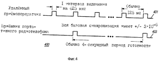
Цифровой радиотелефон использует два основных режима работы, а именно: режим контроля и режим связи. В режиме контроля портативный радиотелефон осуществляет прерывистый прием пэйджинговой информации от удаленного приемопередатчика, ожидая при этом либо приема, либо заказа телефонного вызова с использованием радиотелефона. После начальной запитки портативный радиотелефон включает радиоприемник до тех пор, пока радиоприемник не примет кадр информации от удаленного приемопередатчика, который содержит всю синхронизирующую информацию для радиотелефона. Как только синхронизирующая информация принята, портативный радиотелефон принимает пейджинговую информацию на прерывистой основе. На фиг. 4 представлены временные характеристики, требуемые для обычной радиотелефонной системы, определяемой техническими условиями RCR (стандартные технические условия на телефонные системы с батарейным питанием второго поколения, август 1992, часть 4.2.7). Временной график 401 иллюстрирует временные характеристики для удаленного приемопередатчика, а временной график 403 соответствует временному режиму работы радиоприемника, используемого в портативном радиотелефоне. Обычно портативный радиоприемник включается на один временной интервал (слот) каждые 4 с, или 0,0156%, как вытекает из технических условий RCR. A digital radiotelephone uses two main operating modes, namely: monitoring mode and communication mode. In control mode, the portable radiotelephone intermittently receives paging information from a remote transceiver, while waiting for either receiving or ordering a telephone call using the radiotelephone. After initial power-up, the portable radiotelephone turns on the radio until the radio receiver receives a frame of information from a remote transceiver that contains all the synchronization information for the radiotelephone. Once the synchronization information is received, the portable radiotelephone receives paging information on an intermittent basis. In FIG. Figure 4 shows the time characteristics required for a conventional radiotelephone system defined by the RCR specifications (standard specifications for second-generation battery-powered telephone systems, August 1992, part 4.2.7). The
Хорошо известно, что желательно снизить потребление мощности и увеличить срок службы батареи в портативном радиотелефоне. Таким образом, было бы выгодно отключить по возможности больше схем в течение этого чытерхсекундного периода готовности, чтобы снизить потребление мощности в портативном радиотелефоне. Кроме того, было бы выгодно осуществить эту процедуру сбережения мощности в портативном радиотелефоне экономичным образом. It is well known that it is desirable to reduce power consumption and increase battery life in a portable cordless telephone. Thus, it would be advantageous to disable as many circuits as possible during this four second standby time in order to reduce power consumption in the portable radiotelephone. In addition, it would be advantageous to carry out this power saving procedure in a portable radiotelephone in an economical manner.
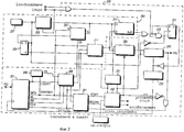
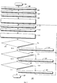
На фиг. 1 изображена блок-схема радиотелефонной системы связи; на фиг. 2 - блок-схема контроллера для использования в радиотелефоне в соответствии с изобретением; на фиг. 3 - блок-схема алгоритм обработки в соответствии с изобретением; на фиг. 4 - временная диаграмма, соответствующая изобретению. In FIG. 1 shows a block diagram of a radiotelephone communication system; in FIG. 2 is a block diagram of a controller for use in a radiotelephone in accordance with the invention; in FIG. 3 is a flowchart of a processing algorithm in accordance with the invention; in FIG. 4 is a timing chart according to the invention.
В принципе предпочтительно выполнение охватывает портативный радиотелефон, действующий в системе радиосвязи. Система радиосвязи имеет два режима работы: режим контроля и режим связи. Радиотелефонная система рассчитана так, что в режиме контроля портативный радиотелефон осуществляет только прием с прерываниями пэйджинговой информации от удаленного приемопередатчика. Для того чтобы сберечь мощность и стоимость, радиотелефон использует дешевый маломощный кварцевый генератор частоты 32 кГц или недорогой RC (резистивно-емкостной) генератор вместе с аппаратными и программными средствами для отключения некоторых элементов радиотелефона, если отсутствует прием информации от удаленного приемопередатчика. К выключаемым элементам радиоприемника относится генератор опорной частоты. In principle, it is preferred that the implementation covers a portable radiotelephone operating in a radio communication system. The radio communication system has two operating modes: monitoring mode and communication mode. The radiotelephone system is designed so that in the control mode the portable radiotelephone only receives interrupted paging information from a remote transceiver. In order to save power and cost, the radiotelephone uses a cheap low-power 32 kHz crystal oscillator or an inexpensive RC (resistive-capacitive) generator along with hardware and software to disconnect some elements of the radiotelephone if there is no reception of information from a remote transceiver. Switchable radio elements include a reference frequency generator.
На фиг. 1 представлена блок-схема радиотелефонной системы в соответствии с изобретением. В радиотелефонной системе удаленный приемопередатчик 103 посылает высокочастотные (ВЧ) сигналы на подвижные и портативные радиотелефоны и принимает от них ВЧ сигналы в заданной области пространства, обслуживаемой этим удаленным приемопередатчиком 103. Радиотелефон 101 является одним из таких радиотелефонов, обслуживаемых удаленным приемопередатчиком 103. In FIG. 1 is a block diagram of a radiotelephone system in accordance with the invention. In a radiotelephone system, the remote transceiver 103 sends high frequency (HF) signals to mobile and portable radiotelephones and receives HF signals from them in a predetermined area of the space served by this remote transceiver 103. The radiotelephone 101 is one of such radiotelephones serviced by the remote transceiver 103.
При приеме сигналов от удаленного приемопередатчика 103 радиотелефон 101 использует антенну 105 для улавливания ВЧ сигнала и для преобразования ВЧ сигнала в электрический ВЧ сигнал. Электрические ВЧ сигналы принимаются радиоприемником 107 для использования в радиотелефоне 101. Приемник 107 демодулирует принятый электрический ВЧ сигнал и выдает символьный сигнал для использования контроллером 111. Контроллер 111 форматирует символьный сигнал в речевой сигнал или данные для использования пользовательским интерфейсом 113. Пользовательский интерфейс 113 используется для передачи информации между пользователем и радиотелефоном 101 и обычно включает микрофон, громкоговоритель, дисплей и клавиатуру. When receiving signals from a remote transceiver 103, the radiotelephone 101 uses an antenna 105 to pick up the RF signal and to convert the RF signal to an electrical RF signal. The RF electrical signals are received by the radio 107 for use in the radiotelephone 101. The receiver 107 demodulates the received RF electrical signal and provides a symbol signal for use by the controller 111. The controller 111 formats the symbol signal into a speech signal or data for use by the user interface 113. The user interface 113 is used for transmission information between the user and the cordless telephone 101 and typically includes a microphone, speaker, display, and keyboard.
При передаче ВЧ сигналов от портативного радиотелефона 101 на удаленный приемопередатчик 103 речевые сигналы и/или данные от пользовательского интерфейса 113 обрабатываются контроллером 111. Обработанные сигналы вводятся в передатчик 109. Передатчик 109 преобразует данные в электрические ВЧ сигналы. Электрические ВЧ сигналы преобразуются в ВЧ сигналы и выдаются на антенну 105. ВЧ сигналы принимаются удаленным приемопередатчиком 103 и преобразуются для использования наземной линейной телефонной системой. When transmitting RF signals from the portable radiotelephone 101 to the remote transceiver 103, voice signals and / or data from the user interface 113 are processed by the controller 111. The processed signals are input to the transmitter 109. The transmitter 109 converts the data into electrical RF signals. The electrical RF signals are converted to RF signals and output to the antenna 105. The RF signals are received by the remote transceiver 103 and converted for use by the land line telephone system.
Кроме того, контроллер 111 используется для управления мощностью приемника 107 и содержащихся в нем схем. На фиг. 2 представлена в виде блок-схемы схема 200 управления потреблением мощности, содержащаяся в контроллере 111. Микропроцессор 201 принимает тактовые импульсы и сигналы прерывания и генерирует сигналы адресной шины, сигналы шины данных и сигналы AS, R/W и E-CLK шины управления. Адресная шина и шина данных соединены с постоянным запоминающим устройством (ПЗУ) 245, которое подает команды и данные на микропроцессор 201. В предпочтительном выполнении микропроцессор 201 представляет собой микропроцессор типа МС68НС11, выпускаемый фирмой "Моторола, Инк". Все шинные выходные сигналы микропроцессора 201 воспринимаются адресным декодирующим регистром 240. Адресный декодирующий регистр 240 генерирует сигналы выделенных линий для регистра 211 длительности счета, регистра 207 значения отсчета и регистра 241 управления с отображением в памяти. Регистр 241 управления с отображением в памяти фиксирует данные от микропроцессора 201, когда действует сигнал выбора от адресного декодирующего регистра 240. Регистр 241 управления с отображением в памяти выдает сигналы запуска таймера и возобновления таймера. Эти выходные сигналы и сигнал, индицирующий нажатие клавиши, принимаются логическим блоком 242 интерфейса, который генерирует импульсы в моменты передних фронтов входных сигналов на основании текущего состояния таймера генератора. Логический блок 202 интерфейса генерирует также управляющий входной сигнал для сумматора/компаратора 250. In addition, the controller 111 is used to control the power of the receiver 107 and the circuits contained therein. In FIG. 2 is a block diagram of a power
В схеме 200 управления потреблением мощности имеются два первичных счетчика, а именно счетчика 203 генератора и счетчик 251 таймера клавиатуры. Эти два счетчика тактируются низкочастотным генератором 237. В предпочтительном выполнении в качестве низкочастотного генератора используется генератор на 32 кГц. In the power
Счетчик 203 генератора обнуляется по сигналу запуска, принятому от логического блока 242 интерфейса. Выходной сигнал счетчика 203 генератора сравнивается с величиной длительности счета, запрограммированной в регистре 211 длительности компаратором 217. Счетчик 203 генератора изменяет состояние асинхронно по сигналу E_CLK от микропроцессора 201. Триггер 205 и регистр 207 значения от счета используются для выравнивания изменений данных счетчика 203 генератора по сигналу E_CLK. Выходной сигнал компаратора - сигнал управления мощностью - используется для включения опорного генератора 233 через управляющий триггер 231. Опорный генератор 233 выключается, когда управляющий триггер 231 принимает либо импульс запуска, либо импульс возобновления от логического блока 242 интерфейса. Импульс нажатия клавиши от логического блока 242 интерфейса объединяется по схеме ИЛИ с выходным сигналом компаратора 217 так, что он тоже может включить опорный генератор в управляющей триггер 231. Выходной сигнал опорного генератора 233 делится по частоте и используется в качестве тактового входного сигнала для микропроцессора 201. Счетчик 203 генератора, регистр 207 значения отсчета, регистр 211 длительности счета, компаратор 217 и низкочастотный генератор 237 образуют синхронизирующее устройство 253. The
Второй счетчик в конструкции является таймером 251 клавиатуры. Счетчик 251 клавиатуры используется для задержки прерывания на микропроцессор 201 после нажатия клавиши. Выходной сигнал таймера 251 клавиатуры подается в сумматор/компаратор 250, который вырабатывает сигналы прерывания для микропроцессора 201. Сигнал прерывания для микропроцессора 201 задерживается на программируемое время задержки после того, как включается опорный генератор 233. Программируемое время задержки позволяет опорному генератору 233 стабилизироваться до того, как схемы запитываются микропроцессором 201. После получения сигналов прерывания микропроцессор 201 определяет, вызваны ли они нажатием клавиши. Если нажатия клавиши нет, микропроцессор 201 устанавливает аппаратуру на прием ожидаемого УС (уникального слова). Если имеет место нажатие клавиши, микропроцессор 201 обрабатывает нажатие клавиши. Затем микропроцессор 201 считывает текущее значение счетчика генератора и сравнивает его со значением длительности счета. Микропроцессор возобновляет интервал отключения, если разность между текущим значением счетчика и значением длительности счета достаточно велика. Если микропроцессор 201 не возобновляет интервал ожидания, микропроцессор 201 контролирует значение счетчика генератора до тех пор, пока оно не сравняется со значением длительности счета плюс программируемое время задержки. The second counter in the design is a
Сумматор/компаратор 250 принимает следующие входные сигналы: выходной сигнал таймера 251 клавиатуры, выходной сигнал счетчика 203 генератора, значение длительности счета от регистра 211 длительности, сигнал сравнения задержки от регистра 211 длительности и управляющий разряд от блока логики 242 интерфейса. Если управляющий разряд от блока логики 242 интерфейса индуцирует нажатие клавиши, то сумматор/компаратор 250 сравнивает сигнал таймера 251 клавиатуры с результатом сравнения задержки от регистра 211 длительности для выработки сигнала прерывания. Если блок логики 242 интерфейса не индицирует нажатия клавиши, то сумматор/компаратор 250 сравнивает значение отсчета от счетчика 203 генератора с суммой результатов сравнения счета и задержки от регистра 211 длительности. Выходной сигнал сумматора/компаратора 250 принимается интерфейса 243 запроса прерывания, который использует управляющий сигнал опорного генератора и низкочастотный генератор 237 генерирования импульса действительного прерывания, который принимается микропроцессором 201. The adder /
Импульс прерывания объединяется также по схеме И с инвертированным управляющим разрядом от блока логики 242 интерфейса для выработки сигнала, который показывает, что прерывание было вызвано нажатием клавиши. Этот сигнал используется для записи бита в регистр 241 управления с отображением в памяти. Регистр управления с отображением в памяти выдает также сигнал установки таймера и сигнал возобновления таймера. Микропроцессор 201 считывает регистр 241 управления с отображением в памяти для определения того, вызвано ли прерывание нажатием клавиши. Бит в регистре 241 управления с отображения в памяти стирается после того, как микропроцессор 201 считает регистр 241. The interrupt pulse is also combined according to the AND circuit with an inverted control bit from the
В режиме контроля портативный радиотелефон 101 принимает с прерываниями пэйджинговую информацию от удаленного приемопередатчика 103. При начальной запитке портативный радиотелефон 101 запитывает свой приемник 107 до тех пор, пока приемник 107 не примет кадр информации от удаленного приемопередатчика, который содержит всю информацию синхронизации для радиотелефона 101. Когда эта информация синхронизации принята, портативный радиотелефон 101 начинает прием на основе прерываний (фиг. 4). В этом режиме приема с прерываниями портативный радиотелефон 101 может экономить потребление мощности путем выключения как можно большего числа схем. In monitoring mode, the portable radiotelephone 101 intermittently receives paging information from the remote transceiver 103. During initial power-up, the portable radiotelephone 101 powers its receiver 107 until the receiver 107 receives a frame of information from the remote transceiver that contains all the synchronization information for the radiotelephone 101. When this synchronization information is received, the portable radiotelephone 101 starts receiving based on interruptions (FIG. 4). In this intermittent receive mode, the portable cordless telephone 101 can save power by turning off as many circuits as possible.
На фиг. 3 представлена блок-схема алгоритма обработки 300, выполняемой радиотелефонной системой 100 для управления потреблением в ней мощности. Обработка 300 начинается с непрерывной подачи питания на радиоприемник 107 (блоки 303). Удаленный приемопередатчик 103 передает интервал (блока 305), содержащий уникальное слово (УС), идентификатор приемопередатчика и информацию синхронизации, как определено техническими условиями RCR, на радиотелефон 101. УС представляет собой заранее заданную последовательность, индицирующую начало каждого временного интервала (слота). Радиотелефон 101 принимает интервал (блок 307), содержащий информацию синхронизации. Кроме того, контроллер 111 считывает текущее значение счетчика ожидания из регистра 207 значения отсчета. Затем радиотелефон 101 ожидает приема следующего временного интервала, переднего от удаленного приемопередатчика 103 на основании принятой информации синхронизации. В это время опорной генератор 233 и микропроцессор 201 остаются запитаными, обеспечивая контроль синхронизации для интервала приема с прерываниями. In FIG. 3 is a flowchart of a
Затем осуществляется вычисление значения длительности ожидания (блок 309). При работающем опорном генераторе 233 контроллер 111 ожидает приема следующего интервала. После приема следующего интервала контроллера 111 считывает текущее значение счетчика генератора и вычитает ранее считанное значение счетчика генератора. Значение длительности ожидания равно этой разности, уменьшенной на время установки. Время установки определяется характеристиками конкретного приемника и опорного генератора в радиотелефоне. В предпочтительном выполнении время установки равно 30 мс. Считывание значений счетчика генератора с использованием опорного генератора 233 в качестве опорной синхронизации автоматически калибрует счетчик 203 генератора на интервал приема с прерываниями независимо от точной частоты низкочастотного генератора 237. Then, the value of the waiting time is calculated (block 309). With the
Регистр 211 подсчитанной длительности программируется предварительно подсчитанным значением длительности отключения (блок 311). The counted
Контроллер 111 отключает первую часть радиоприемника (блок 313). В предпочтительном выполнении отключаемая схема содержит приемник 107 и часть контроллера 111, включая микропроцессор 201 и опорный генератор 233. Микропроцессор 201 отключается по команде "Стоп", отключающей все внутренние тактирующие сигналы. Микропроцессор 201 возобновляет обработку только при выполнении внешнего прерывания. Отметим, что количество и состав отключаемых схем могут изменяться для конкретных применений, что находится в пределах объема изобретения. The controller 111 turns off the first part of the radio (block 313). In a preferred embodiment, the disconnectable circuit comprises a receiver 107 and part of a controller 111, including a
Синхронизирующее устройство 253 включает опорный генератор 233 (блок 315) ожидает заранее заданный интервал времени, затем посылает команду прерывания на микропроцессор 201. Заранее заданное значение времени равно ранее рассмотренному времени включения. После приема команды прерывания микропроцессор 201 включает ранее отключенные схемы. The
Согласно блоку 312 принятия решения, контроллер 111 осуществляет проверку того, не принято ли неверное УС, пока радиоприемник 107 полностью запитан. Имеется две потенциальные причины неверного УС обнаружения, а именно случайный шум и прием УС от другого удаленного приемопередатчика. Причины и вероятность приема неверного УС в предпочтительном выполнении изложены далее. According to decision block 312, the controller 111 checks to see if an incorrect US has been received while the radio 107 is fully powered. There are two potential causes of incorrect US detection, namely random noise and US reception from another remote transceiver. The reasons and probability of receiving an incorrect CSS in the preferred embodiment are described below.
Если принято неверное УС, значение таймера увеличивается (блок 314). Путем увеличения значения таймера окно, в котором приемник 107 может потенциально принять неверное УС, уменьшается. Когда значение таймера увеличено, обработка возвращается к блоку 311. If an invalid CSS is received, the timer value is increased (block 314). By increasing the value of the timer, the window in which the receiver 107 can potentially receive an incorrect US is reduced. When the timer value is increased, processing returns to block 311.
Если в блоке 312 установлено, что неверное УС не принято, то в процессе обработки 300 осуществляется проверка, чтобы убедиться, принято ли правильное УС (блок 321). Контроллер 111 оценивает УС путем проверки содержимого данных, которые следуют за УС. Данные содержат такую информацию, как идентификатор удаленного приемопередатчика, который контроллер 111 может использовать для проверки того, от правильного ли приемопередатчика пришла информация. If it is determined in
Когда принято правильное УС, в блоке 326 получается новое значение длительности счета. Новое значение длительности счета получается с использованием текущего значения длительности счета. В частности, в процессе обработки проверяется величина времени, прошедшего между моментом, когда предыдущий сигнал запуска был выдан логическим блоком 242 интерфейса, и временем, когда было принято УС, и соответственно подстраивает значение длительности счета. Когда новое значение длительности счета получено, процесс обработки 300 возвращается к блоку 311. When the correct CSS is received, in block 326 a new value of the duration of the count is obtained. The new value of the duration of the account is obtained using the current value of the duration of the account. In particular, during processing, the amount of time elapsed between the moment when the previous trigger signal was issued by the
Если правильное УС не принято, как обнаруживается при проверке в блоке 321 решения, то в блоке 325 решения осуществляется проверка того, прошло ли 10 c с момента приема последнего УС (блок 315). Если 10 с не прошло, то в процессе обработки 300 значение таймера уменьшается (блок 323) и обработка возвращается к блоку 311. Если 10 с прошло, то процесс обработки заканчивается в блоке 327. В предпочтительном выполнении, когда прошло 10 с, обработка переходит к блоку 303. If the correct CSS is not accepted, as detected during the verification in
Можно предложить иной способ вычисления значения таймера в блоке 309. Это альтернативное вычисление зависит от типа низкочастотного генератора 237. Предпочтительным вследствие низкой стоимости является использование кварцевого генератора C-типа фирмы "Эпсон". Этот кварцевый генератор имеет допуск на уход частоты ±20•10-6 при 23oC и 200•10-6 в диапазоне от -10 до +60oC. Допуск ±200•10-6 дает заметную временную ошибку, после четырехсекундной готовности, ± 0,8 мс. Эта временная ошибка переводится во включение приемника на 2,5 интервала раньше, чем нужно, как подобно объяснено ниже.A different method can be proposed for calculating the timer value in
Временная ошибка из-за большого допуска по частоте является проблемой, когда портативный радиотелефон 101 пытается синхронизироваться с удаленным приемопередатчиком 103. Проблема при попытке портативного радиотелефона 101 включить свой радиоприемник 107 в подходящее время, чтобы принимать с прерываниями информацию от удаленного приемопередатчика 103 на основании синхронизации от кварцевого генератора с большой ошибкой. Для того чтобы скомпенсировать наихудшую временную ошибку ±0,8 мс, портативный радиотелефон 101 должен включать свой радиоприемник 107 по меньшей мере на 0,8 мс раньше. Это ранее включение по времени вместе с временной ошибкой 0,8 мс означает, что радиоприемник 107 может быть включен за 1,6 мс до приема информации от удаленного приемопередатчика 103. Эти 1,6 мс преобразуются в 2,5 интервала, как определено техническими условиями RCR. В течение этих 2,5 интервалов радиоприемник 107 может выбрать уникальное слово (УС) синхронизирующей последовательности с ошибкой, приводя к возможности обнаружения неверного УС. A temporary error due to the large frequency tolerance is a problem when the portable radiotelephone 101 tries to synchronize with the remote transceiver 103. The problem is when the portable radiotelephone 101 tries to turn on its radio 107 at an appropriate time to receive interrupt information from the remote transceiver 103 based on synchronization from crystal oscillator with a big mistake. In order to compensate for the worst temporary error of ± 0.8 ms, the portable radiotelephone 101 must turn on its radio 107 at least 0.8 ms earlier. This earlier inclusion in time along with a time error of 0.8 ms means that the radio 107 can be turned on 1.6 ms before receiving information from the remote transceiver 103. These 1.6 ms are converted into 2.5 intervals, as determined by the technical conditions RCR During these 2.5 slots, the radio 107 may select a unique sync sequence word (AC) with an error, leading to the possibility of detecting an incorrect US.
Более конкретно значение таймера вычисляется следующим образом:
Tperiod=(Ti•Tfr)-(Ti•Tfr) • Ctol.More specifically, the timer value is calculated as follows:
T period = (T i • T fr ) - (T i • T fr ) • C tol .
Значение таймера равно
(Tperiod-Tnow)/Tcrystal,
где
1. Tperiod - регулируемый период приема с прерываниями;
2. Ti - информация синхронизации в виде числа кадров МДВР между приемами;
3. Tfr - период кадра МДВР, равный 5 мс;
4. Tnow - текущее время с момента последнего включения приемника;
5. Tcrystal - период тактового кварцевого генератора;
6. Ctol - допуск кварцевого генератора, умноженный на 10-6.Timer value is equal
(T period -T now ) / T crystal ,
Where
1. T period - an adjustable period of admission with interruptions;
2. T i - synchronization information in the form of the number of TDMA frames between receptions;
3. T fr - period mdvr frame equal to 5 ms;
4. T now - the current time since the last time the receiver was turned on;
5. T crystal - period of the clock crystal oscillator;
6. C tol - tolerance of the crystal oscillator multiplied by 10 -6 .
Когда принято нужное УС, значение длительности отключения может быть установлено с использованием предыдущего значения счетчика, считанного со счетчика 203 генератора, как рассмотрено ранее для блока 326. Микропроцессор 201 может динамически считывать число тактовых импульсов частоты 32 кГц между следующими друг за другом УС и может использовать это значение для программирования следующего периода отключения. Поскольку разрешающая способность кварцевого генератора медленно изменяется во времени, микропроцессор считывает различные значения счетчика между УС и программирует регистр длительности счета соответственно. Этот способ действует потому, что кварцевый генератор остается стабильным между следующими друг за другом УС. When the desired US is received, the value of the shutdown duration can be set using the previous counter value read from the
Без использования в предпочтительном выполнении изобретения вероятность приема неверного УС либо из-за приема случайного шума, либо из-за приема УС от другого удаленного приемопередатчика вызывает проблемы в системе. Во-первых, возможность приема неверного 32 разрядного УС, вызванного случайным шумом, чрезвычайно низка. Если приемник непрерывно включен, вероятность приема неверного УС равна частоте бит в секунду на последовательность из 32 бит, что составляет 384000/232=0,000089 в секунду. Это соответствует одному неверному обнаружению на 186 мин. Поскольку приемное окно открыто на 2,5 временного интервала (слота) за 4 с, действительная вероятность приема неверного УС равна 0,000089•2,5 интервала раз за 625 мкм/4 с. Это соответствует одному неверному обнаружению за 331 день.Without the use in the preferred embodiment of the invention, the probability of receiving an incorrect US, either due to the reception of random noise, or due to the reception of the US from another remote transceiver, causes problems in the system. Firstly, the possibility of receiving an incorrect 32-bit US caused by random noise is extremely low. If the receiver is continuously turned on, the probability of receiving an incorrect US is equal to the frequency of bits per second per sequence of 32 bits, which is 384000/2 32 = 0.000089 per second. This corresponds to one incorrect detection for 186 minutes. Since the receiving window is open for 2.5 time intervals (slots) for 4 s, the actual probability of receiving an invalid CSS is 0.000089 • 2.5 times for 625 μm / 4 s. This corresponds to one incorrect detection in 331 days.
Во-вторых, возможность приема неверного УС от другого удаленного приемопередатчика весьма высока, когда портативный телефон включает приемник для приема приходящего интервала с определением для компенсации допуска кварцевого генератора. Поскольку в предпочтительном выполнении удаленный приемопередатчик передает самое большее восемь раз в секунду, соответствующее временное окно составляет 1 с/8 интервалов или 125 мс/интервал. Для одного соседнего удаленного приемопередатчика вероятность приема соседнего УС вычисляется следующим образом:
P = Trxwin/Ttxwin = 0,01248 = 1,25%,
где
1. Trxwin = T txclk • 2,5 интервала • 240 тактов/интервал = 1,56 мс = окно приема приемника портативного радиотелефона;
2. Ttxwin - окно передачи соседней базы для 8 интервалов/с, равное 125 мс;
3. Ttxclk - тактовый период передачи, равный 2,6 мкм;
4. P - вероятность приема соседнего УС.Secondly, the possibility of receiving an incorrect US from another remote transceiver is very high when the portable telephone turns on the receiver to receive the incoming interval with the definition to compensate for the tolerance of the crystal oscillator. Since, in a preferred embodiment, the remote transceiver transmits at most eight times per second, the corresponding time window is 1 s / 8 intervals or 125 ms / interval. For one neighboring remote transceiver, the probability of receiving a neighboring US is calculated as follows:
P = T rxwin / T txwin = 0.01248 = 1.25%,
Where
1. T rxwin = T txclk • 2.5 intervals • 240 clocks / interval = 1.56 ms = receiver window of a portable radiotelephone;
2. T txwin - transmission window of the neighboring base for 8 intervals / s, equal to 125 ms;
3. T txclk - transmission clock period equal to 2.6 microns;
4. P is the probability of receiving the neighboring CSS.
Поэтому вторая причина - соседство удаленных приемопередатчиков - является главной причиной весьма высокой вероятности (1,25%) приема неверного УС. Прием неверного УС приводит к пропуску требуемого УС, что может вызвать пропуск приходящего телефонного вызова. Therefore, the second reason - the proximity of remote transceivers - is the main reason for the very high probability (1.25%) of receiving an incorrect US. Reception of an incorrect UX leads to a miss of the required UX, which can cause a miss of an incoming telephone call.
При использовании предпочтительного выполнения с альтернативным вариантом вычисления значения таймера любая ошибка синхронизации от низкочастотного генератора 237 уменьшается до разрешающей способности таймера 203 генератора. Эта ошибка разрешающей способности имеет место потому, что УС может приниматься во время любой части отдельного периода таймера. Максимальная ошибка из-за разрешающей способности счетчика генератора во время периода отключения составляет два тактовых периода: один тактовый период для таймера, устанавливаемого в любой части тактового периода, и второй тактовый период потому, что предыдущее значение таймера могло считываться в любой части тактового периода. Эта ошибка преобразуется во время 62,5 мкс для кварцевого генератора 32 кГц ± 0. Using the preferred embodiment with an alternative calculation of the timer value, any synchronization error from the low-
Общая ошибка, подлежащая компенсации, равна сумме ошибки, вызванной разрешающей способностью счетчика генератора, и ошибки, вызванной синхронизацией удаленного приемопередатчика. Удаленный приемопередатчик 103 должен выдавать УС каждые 4 c с точностью 3•10-6, что в худшем случае дает ошибку 12 мкс. Таким образом, общая ошибка, подлежащая компенсации, равна 75 мкс. Из-за этой ошибки разрешения приемное окно должно быть открыто 150 мкс. Эта величина представляет собой долю интервала 1,6 мс, требуемого без использования изобретения.The total error to be compensated is the sum of the error caused by the resolution of the generator counter and the error caused by the synchronization of the remote transceiver. The remote transceiver 103 should issue a DC every 4 s with an accuracy of 3 • 10 -6 , which in the worst case gives an error of 12 μs. Thus, the total error to be compensated is 75 μs. Due to this resolution error, the receive window must be open 150 μs. This value is a fraction of the 1.6 ms interval required without using the invention.
Вероятность приема неверного УС вследствие рассмотренных условий при использовании предпочтительного выполнения с альтернативным вычислением значения таймера вычисляется следующим образом:
1. Вследствие случайного шума: 0,000089•150 мкс/4=1 неверное УС за 9,5 года.The probability of receiving an incorrect CSS due to the considered conditions when using the preferred execution with an alternative calculation of the timer value is calculated as follows:
1. Due to random noise: 0.000089 • 150 μs / 4 = 1 incorrect CSS for 9.5 years.
2. Вследствие УС от другого удаленного приемопередатчика: 20,8•10-6•58= 0,12%.2. Due to the DC from another remote transceiver: 20.8 • 10 -6 • 58 = 0.12%.
Данное вычисление является теоретической вероятностью. В действительности измеренная вероятность будет близка к нулю, поскольку успешные приемы УС от удаленного приемопередатчика 103 будут вклиниваться в прием неверного УС от других удаленных приемопередатчиков. This calculation is a theoretical probability. In fact, the measured probability will be close to zero, since successful US transmissions from a remote transceiver 103 will wedge into an incorrect US transceiver from other remote transceivers.
Таким образом, использование предпочтительного выполнения с альтернативным вычислением значения таймера снижает вероятность приема неверного УС с 1,25% до 0,12%. Кроме того, использование предпочтительного выполнения с предпочтительным вычислением значения таймера снижает вероятность приема неверного УС еще больше. Снижение вероятности достигается путем исключения из вычисления значения таймера зависимости от точности низкочастотного генератора, как описано выше. Изобретение позволяет снизить потребление энергии радиотелефоном 101 при обеспечении эффективной защиты при приеме уникальных слов с использованием низкочастотного генератора. Thus, the use of a preferred embodiment with an alternative calculation of the timer value reduces the likelihood of receiving an incorrect CSS from 1.25% to 0.12%. In addition, the use of the preferred execution with the preferred calculation of the timer value reduces the likelihood of receiving an incorrect CSS even more. The probability reduction is achieved by excluding from the calculation of the timer value the dependence on the accuracy of the low-frequency generator, as described above. The invention allows to reduce the energy consumption of the radiotelephone 101 while providing effective protection when receiving unique words using a low-frequency generator.
Claims (6)
А) запитку радиоприемника,
В) прием радиоприемником информации синхронизации,
С) вычисление значения длительности счета в ответ на информацию синхронизации,
D) программирование синхронизирующего устройства значением длительности счета,
Е) отключение первой части схем радиоприемника, содержащей по меньшей мере генератор опорной частоты,
F) включение первой части схем радиоприемника в ответ на соответствующую индикацию от синхронизирующего устройства,
G) увеличение значения длительности счета в ответ на прием неверного уникального слова схемами радиоприемника,
H) повторение операций D) - G) до тех пор, пока не выполнится первое условие, выбранное из группы, состоящей из завершения первого заранее заданного интервала времени и приема правильного уникального слова,
I) уменьшение значения длительности счета в ответ на завершение первого заранее заданного интервала времени,
J) повторение операций A) - H) в ответ на упомянутую операцию уменьшения,
K) вычисление нового значения длительности счета в ответ на прием правильного уникального слова и
L) повторение операций D) - J) в ответ на операцию вычисления нового значения длительности счета.5. A method for controlling a radio receiver in a radio communication system comprising a first radio receiver and a first remote transceiver, the transceiver transmitting synchronization information and unique words, and the radio receiving unique words and comprising a first low-frequency generator, a reference frequency generator, and a user interface, characterized in that it includes operations :
A) powering the radio,
C) receiving a radio receiver synchronization information,
C) calculating a count duration value in response to synchronization information,
D) programming the synchronization device with the value of the counting duration,
E) disabling the first part of the radio circuits containing at least a reference frequency generator,
F) the inclusion of the first part of the circuits of the radio in response to the appropriate indication from the synchronizing device,
G) increasing the value of the duration of the count in response to the reception of an incorrect unique word by the radio circuits,
H) repeating operations D) - G) until the first condition selected from the group consisting of completing the first predetermined time interval and receiving the correct unique word is satisfied,
I) reducing the duration of the count in response to the completion of the first predetermined time interval,
J) repetition of operations A) to H) in response to said reduction operation,
K) calculating a new value for the duration of the count in response to receiving the correct unique word and
L) repetition of operations D) - J) in response to the operation of calculating a new value for the duration of the count.
M) включение второй части схем радиоприемника в ответ на соответствующую индикацию от пользовательского интерфейса, причем вторая часть схем радиоприемника входит в состав первой его части,
N) обработку индикации от пользовательского интерфейса,
О) сравнение значения длительности счета с текущим состоянием синхронизирующего устройства и принятие первого решения и
P) повторение операций E) или операции F) в ответ на первое решение в операции О).6. The method according to claim 5, characterized in that the operation F) includes
M) the inclusion of the second part of the radio circuits in response to a corresponding indication from the user interface, the second part of the radio circuits being part of the first part,
N) processing indications from the user interface,
O) comparing the value of the duration of the account with the current state of the synchronizing device and the adoption of the first decision and
P) repetition of operations E) or operation F) in response to the first decision in operation O).
Applications Claiming Priority (3)
| Application Number | Priority Date | Filing Date | Title |
|---|---|---|---|
| US08/130,612 | 1993-10-01 | ||
| US08/130,612 US5428820A (en) | 1993-10-01 | 1993-10-01 | Adaptive radio receiver controller method and apparatus |
| PCT/US1994/010037 WO1995010141A1 (en) | 1993-10-01 | 1994-09-08 | Adaptive radio receiver controller method and apparatus |
Publications (2)
| Publication Number | Publication Date |
|---|---|
| RU95112844A RU95112844A (en) | 1997-12-20 |
| RU2110889C1 true RU2110889C1 (en) | 1998-05-10 |
Family
ID=22445505
Family Applications (1)
| Application Number | Title | Priority Date | Filing Date |
|---|---|---|---|
| RU95112844A RU2110889C1 (en) | 1993-10-01 | 1994-09-08 | Radio receiver input power control device and method for controlling radio receiver in radio communication system |
Country Status (12)
| Country | Link |
|---|---|
| US (1) | US5428820A (en) |
| JP (1) | JPH08504075A (en) |
| KR (1) | KR0173014B1 (en) |
| CN (1) | CN1037886C (en) |
| BR (1) | BR9405623A (en) |
| CA (1) | CA2148702C (en) |
| FR (1) | FR2711463A1 (en) |
| GB (1) | GB2289193B (en) |
| RU (1) | RU2110889C1 (en) |
| SG (1) | SG44532A1 (en) |
| WO (1) | WO1995010141A1 (en) |
| ZA (1) | ZA947620B (en) |
Cited By (1)
| Publication number | Priority date | Publication date | Assignee | Title |
|---|---|---|---|---|
| RU2461130C1 (en) * | 2008-07-07 | 2012-09-10 | Квэлкомм Инкорпорейтед | System and method for eliminating pulses in receiver or transmitter |
Families Citing this family (56)
| Publication number | Priority date | Publication date | Assignee | Title |
|---|---|---|---|---|
| JP2647010B2 (en) * | 1994-08-08 | 1997-08-27 | 日本電気株式会社 | Intermittent receiving circuit for radio selective calling receiver |
| US5594776A (en) * | 1994-09-14 | 1997-01-14 | Ericsson Inc. | Efficient paging system |
| GB2297854B (en) * | 1995-02-07 | 1999-04-07 | Nokia Mobile Phones Ltd | Real time clock |
| GB2297883B (en) * | 1995-02-07 | 1999-08-11 | Nokia Mobile Phones Ltd | Radio telephone |
| GB2297884B (en) * | 1995-02-07 | 1999-05-26 | Nokia Mobile Phones Ltd | Radio telephone |
| DE19519450C2 (en) * | 1995-05-26 | 1997-06-12 | Oliver Simons | Control system |
| JP2718399B2 (en) * | 1995-08-10 | 1998-02-25 | 日本電気株式会社 | Data radio for computer connection |
| US5845204A (en) * | 1995-08-11 | 1998-12-01 | Rockwell International Corporation | Method and apparatus for controlling the wakeup logic of a radio receiver in sleep mode |
| US6694146B1 (en) * | 1995-09-25 | 2004-02-17 | Pacific Comm Sciences Inc | Method for reducing time required to receive and decode a temporary equipment identifier message |
| FI111582B (en) * | 1995-10-23 | 2003-08-15 | Nokia Corp | A method and circuit arrangement for compensating for internal thought errors in a mobile station |
| EP0865690B1 (en) * | 1995-12-07 | 2003-02-26 | Vistar Telecommunications Inc. | Wireless packet data distributed communications system |
| US5991279A (en) * | 1995-12-07 | 1999-11-23 | Vistar Telecommunications Inc. | Wireless packet data distributed communications system |
| US7590083B2 (en) * | 1995-12-07 | 2009-09-15 | Transcore Link Logistics Corp. | Wireless packet data distributed communications system |
| JP3694084B2 (en) * | 1996-02-21 | 2005-09-14 | 三菱電機株式会社 | Mobile device |
| JPH09247035A (en) * | 1996-03-08 | 1997-09-19 | Nec Eng Ltd | Low power consumption circuit |
| US5940381A (en) * | 1996-03-14 | 1999-08-17 | Motorola, Inc. | Asynchronous transfer mode radio communications system with handoff and method of operation |
| US5961858A (en) * | 1996-06-06 | 1999-10-05 | Engauge Inc. | Laser welding apparatus employing a tilting mechanism |
| GB2315194B (en) * | 1996-07-11 | 2000-11-15 | Nokia Mobile Phones Ltd | Method and apparatus for resynchronizing two system clocks |
| US6009319A (en) * | 1996-09-06 | 1999-12-28 | Telefonaktiebolaget Lm Ericsson | Method and apparatus for reducing power consumption in a mobile radio communication device |
| EP0868792A2 (en) * | 1996-10-24 | 1998-10-07 | Koninklijke Philips Electronics N.V. | A digital wireless communications system and a wireless radio station |
| US5943613A (en) * | 1996-11-07 | 1999-08-24 | Telefonaktiebolaget Lm Ericsson | Method and apparatus for reducing standby current in communications equipment |
| US6016312A (en) * | 1997-02-28 | 2000-01-18 | Motorola, Inc. | Radiotelephone and method for clock calibration for slotted paging mode in a CDMA radiotelephone system |
| US5856786A (en) * | 1997-03-05 | 1999-01-05 | Northrop Grumman Corporation | Adaptive sleep circuit using network timing feedback |
| US6029061A (en) * | 1997-03-11 | 2000-02-22 | Lucent Technologies Inc. | Power saving scheme for a digital wireless communications terminal |
| US6081733A (en) * | 1997-04-16 | 2000-06-27 | Motorola, Inc. | Communication control apparatus and method |
| JPH10301661A (en) * | 1997-04-23 | 1998-11-13 | Matsushita Electric Ind Co Ltd | Clock supplying device |
| GB2329795B (en) * | 1997-09-27 | 2002-09-25 | Nec Technologies | High resolution clock reconstruction for use in a mobile telecommunication device |
| WO1999022536A2 (en) * | 1997-10-24 | 1999-05-06 | Koninklijke Philips Electronics N.V. | A battery-operated communications device |
| JP4001686B2 (en) | 1997-11-19 | 2007-10-31 | 株式会社日立国際電気 | Receiver, intermittent frame synchronization method, and portable terminal |
| EP0924947A1 (en) * | 1997-12-22 | 1999-06-23 | The Technology Partnership Public Limited Company | Power saving in a digital cellular system terminal |
| US6229988B1 (en) * | 1998-05-20 | 2001-05-08 | Lojack Corporation | Method of and apparatus for battery and similar power source conservation in periodically operable portable and related radio receivers and the like |
| US6473607B1 (en) * | 1998-06-01 | 2002-10-29 | Broadcom Corporation | Communication device with a self-calibrating sleep timer |
| US6480476B1 (en) * | 1998-10-15 | 2002-11-12 | Telefonaktiebolaget Lm Ericsson (Publ) | Variable sleep mode for mobile stations in a mobile communications |
| JP3560489B2 (en) | 1999-02-04 | 2004-09-02 | 埼玉日本電気株式会社 | Communication device, control method, and recording medium for efficiently controlling power supply |
| US6748006B1 (en) | 1999-05-28 | 2004-06-08 | Texas Instruments Incorporated | Method and apparatus for controlling system timing with use of a master timer |
| US6539049B1 (en) | 1999-05-28 | 2003-03-25 | Dot Wireless, Inc. | Device and method for maintaining time synchronous with a network master time |
| US6289067B1 (en) | 1999-05-28 | 2001-09-11 | Dot Wireless, Inc. | Device and method for generating clock signals from a single reference frequency signal and for synchronizing data signals with a generated clock |
| US6281822B1 (en) | 1999-05-28 | 2001-08-28 | Dot Wireless, Inc. | Pulse density modulator with improved pulse distribution |
| US6452959B1 (en) | 1999-05-28 | 2002-09-17 | Dot Wireless, Inc. | Method of and apparatus for generating data sequences for use in communications |
| DE10009683A1 (en) * | 2000-02-29 | 2001-08-30 | Nokia Mobile Phones Ltd | Interrupting communications unit quiescent state, especially in radio communications system, involves reducing time remaining to next activation to time sufficient for activation |
| US6947721B2 (en) * | 2000-05-15 | 2005-09-20 | Texas Instruments Incorporated | Wireless communications with transceiver-integrated frequency shift control and power control |
| DE10100570A1 (en) * | 2001-01-09 | 2002-07-11 | Philips Corp Intellectual Pty | Method and circuit arrangement for recognizing synchronization patterns in a receiver |
| KR100374036B1 (en) * | 2001-03-06 | 2003-02-26 | 삼성전자주식회사 | Apparatus and method for controlling pll to receive quick paging message in mobile communication terminal |
| US6980823B2 (en) * | 2002-01-31 | 2005-12-27 | Qualcomm Inc. | Intermediate wake mode to track sleep clock frequency in a wireless communication device |
| JP3637333B2 (en) * | 2002-07-05 | 2005-04-13 | 株式会社東芝 | Spread spectrum communication apparatus and control method thereof |
| CA2393651A1 (en) * | 2002-07-29 | 2004-01-29 | Ralph Dickson Mason | Low power oscillator and power down method |
| US7610035B2 (en) * | 2002-12-31 | 2009-10-27 | Temic Automotive Of North America, Inc. | System and method for controlling the power in a wireless client device |
| US7596366B2 (en) | 2002-12-31 | 2009-09-29 | Temic Automotive Of North America, Inc. | System and method for controlling the power in a wireless client device |
| US8462858B2 (en) * | 2005-02-18 | 2013-06-11 | Texas Instruments Incorporated | Wireless communications with transceiver-integrated frequency shift control and power control |
| US8509859B2 (en) * | 2005-03-11 | 2013-08-13 | Qualcomm Incorporated | Apparatus and methods for control of sleep modes in a transceiver |
| US20070262853A1 (en) * | 2006-05-05 | 2007-11-15 | Black & Decker Inc. | Vehicle alarm |
| US7734264B2 (en) | 2006-08-29 | 2010-06-08 | Qualcomm Incorporated | System frame number (SFN) evaluator |
| US8217760B2 (en) * | 2008-03-20 | 2012-07-10 | Checkpoint Systems, Inc. | Applique nodes for performance and functionality enhancement in radio frequency identification systems |
| US7974647B2 (en) | 2008-05-16 | 2011-07-05 | Mediatek Inc. | Mobile apparatus and method of timing synchronization |
| KR20170141541A (en) * | 2016-06-15 | 2017-12-26 | 주식회사 벤플 | Beacon device including switch and method for providing service using the same |
| WO2018108295A1 (en) | 2016-12-16 | 2018-06-21 | Telefonaktiebolaget Lm Ericsson (Publ) | Wakeup synchronization for frequency hopping systems |
Family Cites Families (10)
| Publication number | Priority date | Publication date | Assignee | Title |
|---|---|---|---|---|
| US4305041A (en) * | 1979-10-26 | 1981-12-08 | Rockwell International Corporation | Time compensated clock oscillator |
| US4513430A (en) * | 1982-05-24 | 1985-04-23 | Varian Associates, Inc. | Missing or broken wafer sensor |
| JPS6110329A (en) * | 1984-06-25 | 1986-01-17 | Nec Corp | Battery saving device of radio equipment |
| FR2625042B1 (en) * | 1987-12-22 | 1990-04-20 | Thomson Csf | MODULAR HYBRID MICROELECTRONIC STRUCTURE WITH HIGH INTEGRATION DENSITY |
| US5029237A (en) * | 1988-06-30 | 1991-07-02 | At&E Corporation | Radio receiver frequency control system |
| JPH02261226A (en) * | 1989-03-31 | 1990-10-24 | Mitsubishi Electric Corp | Mobile telephone set |
| US5251325A (en) * | 1990-06-04 | 1993-10-05 | Motorola, Inc. | Battery saving method and apparatus for providing selective receiver power switching |
| FI88657C (en) * | 1991-02-12 | 1993-06-10 | Nokia Mobile Phones Ltd | Foerfarande Foer att minska stroemfoerbrukningen i en mobil telefon |
| JP2712868B2 (en) * | 1991-03-30 | 1998-02-16 | 日本電気株式会社 | Selective call receiver |
| FI95980C (en) * | 1992-09-04 | 1996-04-10 | Nokia Mobile Phones Ltd | Method and switchgear for accurate measurement of time with an inaccurate clock |
-
1993
- 1993-10-01 US US08/130,612 patent/US5428820A/en not_active Expired - Lifetime
-
1994
- 1994-09-08 CN CN94190744A patent/CN1037886C/en not_active Expired - Lifetime
- 1994-09-08 GB GB9510797A patent/GB2289193B/en not_active Expired - Lifetime
- 1994-09-08 CA CA002148702A patent/CA2148702C/en not_active Expired - Fee Related
- 1994-09-08 JP JP7510808A patent/JPH08504075A/en active Pending
- 1994-09-08 SG SG1996001608A patent/SG44532A1/en unknown
- 1994-09-08 BR BR9405623-4A patent/BR9405623A/en not_active Application Discontinuation
- 1994-09-08 KR KR1019950702205A patent/KR0173014B1/en not_active IP Right Cessation
- 1994-09-08 WO PCT/US1994/010037 patent/WO1995010141A1/en active Application Filing
- 1994-09-08 RU RU95112844A patent/RU2110889C1/en active
- 1994-09-27 FR FR9411517A patent/FR2711463A1/en active Granted
- 1994-09-29 ZA ZA947620A patent/ZA947620B/en unknown
Cited By (2)
| Publication number | Priority date | Publication date | Assignee | Title |
|---|---|---|---|---|
| RU2461130C1 (en) * | 2008-07-07 | 2012-09-10 | Квэлкомм Инкорпорейтед | System and method for eliminating pulses in receiver or transmitter |
| US8375261B2 (en) | 2008-07-07 | 2013-02-12 | Qualcomm Incorporated | System and method of puncturing pulses in a receiver or transmitter |
Also Published As
| Publication number | Publication date |
|---|---|
| GB9510797D0 (en) | 1995-08-02 |
| SG44532A1 (en) | 1997-12-19 |
| WO1995010141A1 (en) | 1995-04-13 |
| CA2148702C (en) | 2000-07-11 |
| KR0173014B1 (en) | 1999-03-30 |
| JPH08504075A (en) | 1996-04-30 |
| CN1037886C (en) | 1998-03-25 |
| BR9405623A (en) | 1999-09-08 |
| CN1115194A (en) | 1996-01-17 |
| FR2711463B1 (en) | 1997-02-28 |
| US5428820A (en) | 1995-06-27 |
| FR2711463A1 (en) | 1995-04-28 |
| KR950704860A (en) | 1995-11-20 |
| GB2289193A (en) | 1995-11-08 |
| ZA947620B (en) | 1995-05-16 |
| GB2289193B (en) | 1998-04-22 |
Similar Documents
| Publication | Publication Date | Title |
|---|---|---|
| RU2110889C1 (en) | Radio receiver input power control device and method for controlling radio receiver in radio communication system | |
| EP0473465B1 (en) | Power saving arrangement and method in portable cellular telephone system | |
| KR100577545B1 (en) | Synchronisation of a low power clock in a wireless communication device | |
| EP0095750B1 (en) | Battery saving circuit for a portable radio receiver | |
| US5790941A (en) | Method and apparatus for regenerating the symbol clock of a cellular telephone following a sleep cycle | |
| US5369798A (en) | Method and circuit for saving the power of a battery used in a portable radio telephone | |
| US6311081B1 (en) | Low power operation in a radiotelephone | |
| AU3101200A (en) | A wireless telephone that rapidly reacquires a timing reference from a wireless network after a sleep mode | |
| JPS6360934B2 (en) | ||
| US6088576A (en) | Receiver providing signal reception in power-off state | |
| US6728234B1 (en) | Method and apparatus for using a low clock frequency to maintain a time reference governed by a high clock frequency | |
| US6466553B1 (en) | Receiver, intermittent frame synchronizing method and portable remote terminal | |
| USRE43308E1 (en) | Adjustment of period of real-time slow drift correction of alignment of handset's local oscillator for a cordless telephone | |
| GB2368235B (en) | Mobile communications | |
| JP3438062B2 (en) | Mobile terminal | |
| US6650874B1 (en) | Real-time slow drift correction of alignment of handset's local oscillator for cordless telephone | |
| CA2173773C (en) | Method and apparatus for regenerating the symbol clock of a cellular telephone following a sleep cycle | |
| JP3006151B2 (en) | Selective call receiver | |
| JP3006150B2 (en) | Selective call receiver | |
| JP2000049682A (en) | Portable telephone terminal | |
| JPH10145446A (en) | Portable terminal equipment | |
| JPH05347577A (en) | Selective call receiver | |
| JPH09187077A (en) | Mobile station control system for simple portable telephone system | |
| JPH07326999A (en) | Radio equipment for mobile station | |
| JP2000252912A (en) | Mobile radio |