RU2109864C1 - Device for holding stocking in machine for sewing of pantyhoses - Google Patents
Device for holding stocking in machine for sewing of pantyhoses Download PDFInfo
- Publication number
- RU2109864C1 RU2109864C1 RU96109057A RU96109057A RU2109864C1 RU 2109864 C1 RU2109864 C1 RU 2109864C1 RU 96109057 A RU96109057 A RU 96109057A RU 96109057 A RU96109057 A RU 96109057A RU 2109864 C1 RU2109864 C1 RU 2109864C1
- Authority
- RU
- Russia
- Prior art keywords
- flat
- elastic
- stocking
- elastic body
- flat element
- Prior art date
Links
Images
Classifications
-
- D—TEXTILES; PAPER
- D05—SEWING; EMBROIDERING; TUFTING
- D05B—SEWING
- D05B23/00—Sewing apparatus or machines not otherwise provided for
- D05B23/007—Sewing units for assembling parts of knitted panties or closing the stocking toe part
- D05B23/008—Line closers, i.e. sewing units for forming the body portion of the panty hose
-
- D—TEXTILES; PAPER
- D06—TREATMENT OF TEXTILES OR THE LIKE; LAUNDERING; FLEXIBLE MATERIALS NOT OTHERWISE PROVIDED FOR
- D06C—FINISHING, DRESSING, TENTERING OR STRETCHING TEXTILE FABRICS
- D06C5/00—Shaping or stretching of tubular fabrics upon cores or internal frames
- D06C5/005—Shaping or stretching of tubular fabrics upon cores or internal frames of articles, e.g. stockings
Landscapes
- Engineering & Computer Science (AREA)
- Textile Engineering (AREA)
- Socks And Pantyhose (AREA)
- Sewing Machines And Sewing (AREA)
- Treatment Of Fiber Materials (AREA)
Abstract
Description
Изобретение относится к усовершенствованной форме для удержания чулка в машине, предназначенной для сшивания колготок. The invention relates to an improved form for holding a stocking in a machine for stitching tights.
Известно, что для изготовления колготочного изделия вначале необходимо по отдельности надеть или "загрузить" два чулка на парные и совмещенные плоскости формы, а затем выровнять их по вертикали и сместить близко друг к другу, с тем чтобы было обеспечено соответствие между эластичной каймой двух чулок и соответствующими подвязочными линиями, при этом последние образуют линию разграничения между двумя зонами разной плоскости, такими как корсаж и паголенок каждого чулка. После этого расположенные таким образом два чулка должны быть разрезаны в продольном направлении, начиная с эластичной каймы корсажа по длине заданной протяженности. Затем находящиеся в определенном положении каемки разрезанных таким образом чулок должны быть сшиты друг с другом для формирования колготочного изделия, при этом упомянутые формы находятся в оттянутом друг от друга состоянии. It is known that for the manufacture of tights, it is first necessary to individually put on or “load” two stockings onto paired and combined shape planes, and then align them vertically and shift them close to each other so that the correspondence between the elastic rim of the two stockings and corresponding garter lines, the latter forming a line of demarcation between two zones of a different plane, such as a corsage and a pagolenok of each stocking. After that, two stockings located in this way should be cut in the longitudinal direction, starting with the elastic rim of the corsage along the length of a given length. Then, the edges of the stocking cut in such a way should be sewn together to form a pantyhose, while the above-mentioned shapes are in a state drawn from each other.
Из этого следует, что для выполнения разрезания и последующего сшивания двух чулок с требуемой точностью необходимо, чтобы два чулка были бы заблаговременно соответствующим образом установлены и расположены на опорных формах. From this it follows that in order to perform the cutting and the subsequent stitching of two stockings with the required accuracy, it is necessary that the two stockings be properly set in advance and located on the supporting forms.
Наиболее близким аналогом изобретению является форма для удержания чулка, содержащая два плоских контурных элемента, выполненных с возможностью оттягивания друг от друга. The closest analogue of the invention is a form for holding a stocking containing two flat contour elements made with the possibility of pulling from each other.
Однако у упомянутой известной формы имеются недостатки, обусловленные главным образом ее жесткостью, которая заставляет ткань чулок оказывать чрезмерное сопротивление оттягиванию плоских контурных элементов друг от друга. However, the known form has drawbacks, mainly due to its stiffness, which causes the stocking fabric to exert excessive resistance to pulling the planar elements apart.
В основу изобретения положена задача создания формы для удержания чулка, которая за счет конструкции плоских контурных элементов позволяла бы уменьшить сопротивление ткани чулок. Этот результат достигается при оттягивании элементов друг от друга. The basis of the invention is the creation of a form for holding the stocking, which due to the design of flat contour elements would reduce the resistance of the fabric of the stocking. This result is achieved by pulling elements from each other.
Данная задача решается посредством формы для удержания чулка, содержащей два плоских контурных элемента, выполненных с возможностью оттягивания друг от друга, в которой, согласно изобретению, каждый плоский элемент снабжен упругим и эластичным телом на соответствующей наружной стороне, при этом один конец тела неподвижно закреплен на уровне передней части плоского элемента, а другой конец свободен для обеспечения его податливости за счет эластичности и перемещения близко к боковой стороне плоского элемента при оттягивании друг от друга плоских элементов под действием ткани чулка. This problem is solved by means of a form for holding a stocking containing two flat contour elements made with the possibility of pulling away from each other, in which, according to the invention, each flat element is provided with an elastic and elastic body on the corresponding outer side, while one end of the body is fixedly mounted on level of the front of the flat element, and the other end is free to ensure its flexibility due to elasticity and movement close to the side of the flat element when pulling from each other and flat elements under the action of the stocking fabric.
Предпочтительно, чтобы эластичное тело было выполнено из дугообразной пластинки, обращенной вогнутостью к соответствующему плоскому элементу, при этом ее неподвижно закрепленный конец был вставлен в соответствующую боковую прорезь передней части плоского элемента. Preferably, the elastic body was made of an arcuate plate facing concavity to the corresponding flat element, while its fixed end was inserted into the corresponding side slot of the front of the flat element.
Целесообразно, чтобы форма имела неподвижно закрепленный упорный элемент для стопорения наружного перемещения свободного конца эластичного тела в состоянии покоя. It is advisable that the form had a fixedly fixed thrust element for locking the external movement of the free end of the elastic body at rest.
Желательно, чтобы с каждым эластичным телом была взаимосвязана упругая и эластичная пластинка в форме листовой пружины для повышения жесткости эластичного тела в соответствующей центральной зоне, при этом один конец эластичной пластинки находился в зацеплении с плоским элементом, а другой был свободен и близок к эластичному телу. It is desirable that an elastic and elastic plate in the form of a leaf spring is interconnected with each elastic body to increase the rigidity of the elastic body in the corresponding central zone, while one end of the elastic plate is engaged with a flat element and the other is free and close to the elastic body.
Преимущества, вытекающие из изобретения, главным образом заключаются в том, что загрузочная способность форм увеличивается, поскольку представляется возможным устанавливать на одной и той же форме без замены какого-либо ее элемента чулки любого размера и/или любой длины, что всегда можно получить и сохранить правильное положение чулок поверх форм, что быстрая реакция ткани на оттягивание форм друг от друга получается без сопротивления с их стороны, что усовершенствованную форму просто изготовить, причем эта форма эффективна в отношении затрат и надежна даже после продолжительного срока службы. The advantages arising from the invention are mainly that the loading capacity of the molds increases, since it seems possible to install stockings of any size and / or any length on one and the same mold, which can always be obtained and stored the correct position of the stocking on top of the molds, that a quick reaction of the fabric to pulling the molds apart is obtained without resistance on their part, that an improved mold is easy to manufacture, and this mold is effective in cost-effective and reliable even after a long service life.
Эти и другие преимущества и отличительные признаки изобретения наилучшим образом будут поняты квалифицированными специалистами в данной отрасли при прочтении приведенного ниже описания совместно с прилагаемыми чертежами, представленными в качестве примера практического осуществления изобретения, но которые не следует рассматривать как налагающие определенные ограничения, и на которых:
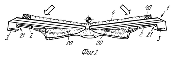
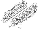
на фиг. 1 представлен вид в плане предлагаемой формы в нерабочем состоянии и без чулка на ней; на фиг. 2 - то же, в растянутом состоянии и с надетым на нее чулком; на фиг. 3 - упрощенный вид в перспективе пары форм такого типа, который представлен на фиг.1.These and other advantages and features of the invention will be best understood by qualified specialists in this field when reading the description below together with the accompanying drawings, presented as an example of practical implementation of the invention, but which should not be construed as imposing certain restrictions, and on which:
in FIG. 1 shows a plan view of the proposed form inoperative and without stocking on it; in FIG. 2 - the same, in a stretched state and with a stocking put on it; in FIG. 3 is a simplified perspective view of a pair of forms of the type shown in FIG.
Предлагаемая форма для удержания чулка содержит два плоских контурных элемента 1. Каждый плоский элемент на его наружной стороне снабжен упругим и эластичным телом 2, лишь один конец 20 которого неподвижно закреплен на передней части 10 плоского элемента 1, а его другой конец 21 свободен, с тем чтобы обеспечить его податливость за счет эластичности, и перемещение этого свободного конца 21 близко к боковой стороне плоской части в течение оттягивания друг от друга плоских элементов, как следствие действия, оказываемого тканью чулка 4 после его разрезания. The proposed shape for holding the stocking contains two flat contour elements 1. Each flat element on its outer side is provided with an elastic and
Эластичное тело 2 предпочтительно состоит из дугообразной пластинки, вогнутость которой обращена к соответствующей форме, а ее неподвижно закрепленный конец 20 вставлен в соответствующую боковую прорезь передней части 10 формы. Этим обеспечивается более легкая сборка. The
Кроме того, в заданном месте формы 1 предпочтительно неподвижно закреплено тело 3, которое обеспечивает упорный элемент для стопорения наружного перемещения свободного конца 21 элемента в состоянии покоя. In addition, in a predetermined location of the mold 1, a
Также предпочтительно, чтобы, как показано на фиг. 1, была обеспечена взаимосвязь каждого тела 2 с упругой и эластичной пластинкой 5 в форме листовой пружины для повышения жесткости тела 2 в соответствующей центральной зоне: с одним концом пластинки 22 входит в зацепление форма для удержания чулка, а другой конец свободен и находится вблизи от тела 2. It is also preferred that, as shown in FIG. 1, the interconnection of each
Использование двух форм для образования колготочного изделия осуществляется следующим образом. The use of two forms for the formation of pantyhose is as follows.
При надевании чулок 4 на формы каждый элемент эластично деформируется пол действием, оказываемым на него эластичной каймой 40 соответствующего чулка до тех пор, пока он не примет уравновешенную конфигурацию, которая определяется характеристиками эластичности этого элемента и изделия, при этом свободный конец 21 отделяется от формы. Таким образом, эластичная кайма и части чулок, предназначенные для формирования корсажа колготок, будут надлежащим образом натянуты, какими бы ни были размер, плотность и длина корсажа и эластичной каймы чулок. После того, как формы перемещены близко друг к другу и известным самим по себе способом выполнено продольное разрезание корсажей, каждый из упомянутых элементов с соответствующим свободным концом 21 подвергается действию эластичной каймы 40 соответствующего чулка 4 и таким образом обеспечивается возможность контроля за приближением к соответствующей форме. Поэтому при выполнении последующей стадии растягивания форм (см. фиг. 2), также осуществляемой согласно известным процессам, на упомянутые формы не будет оказываться действие сопротивления эластичной каймы чулков. When putting the
Практически все конструктивные детали могут изменяться любым эквивалентным образом в отношении их формы, размеров, расположения элементов, природы используемых материалов, но так, чтобы эти изменения не отклонялись от объема идеи изобретения и при этом оставались в пределах защиты, гарантируемой настоящим патентом на промышленное применение. Almost all structural details can be changed in any equivalent way with respect to their shape, size, arrangement of elements, nature of the materials used, but so that these changes do not deviate from the scope of the idea of the invention and at the same time remain within the protection guaranteed by this patent for industrial use.
Claims (4)
Applications Claiming Priority (2)
| Application Number | Priority Date | Filing Date | Title |
|---|---|---|---|
| ITFI95A98 | 1995-05-10 | ||
| IT95FI000098A IT1278667B1 (en) | 1995-05-10 | 1995-05-10 | PERFECT SOCK HOLDER SHAPE FOR SEWING MACHINE-COLLANTS |
Publications (2)
| Publication Number | Publication Date |
|---|---|
| RU2109864C1 true RU2109864C1 (en) | 1998-04-27 |
| RU96109057A RU96109057A (en) | 1998-08-20 |
Family
ID=11351241
Family Applications (1)
| Application Number | Title | Priority Date | Filing Date |
|---|---|---|---|
| RU96109057A RU2109864C1 (en) | 1995-05-10 | 1996-05-08 | Device for holding stocking in machine for sewing of pantyhoses |
Country Status (7)
| Country | Link |
|---|---|
| US (1) | US5669321A (en) |
| EP (1) | EP0742306B1 (en) |
| JP (1) | JPH08325924A (en) |
| CN (1) | CN1144282A (en) |
| DE (1) | DE69603535T2 (en) |
| IT (1) | IT1278667B1 (en) |
| RU (1) | RU2109864C1 (en) |
Families Citing this family (1)
| Publication number | Priority date | Publication date | Assignee | Title |
|---|---|---|---|---|
| IT1292459B1 (en) * | 1997-07-02 | 1999-02-08 | Conti Complett Spa | CONVEYOR FOR SEWING MACHINES FOR CLOSING THE TOE OF SOCKS OR SIMILAR, WITH HIGH VERSATILITY OF USE |
Family Cites Families (10)
| Publication number | Priority date | Publication date | Assignee | Title |
|---|---|---|---|---|
| US1284738A (en) * | 1917-04-19 | 1918-11-12 | William E Mccarthy | Stocking-stretcher. |
| US2639139A (en) * | 1948-09-23 | 1953-05-19 | Robotyper Corp | Spring biased actuator |
| US2643030A (en) * | 1950-01-26 | 1953-06-23 | Gates Mfg Corp | Oil recovery stand |
| US2948447A (en) * | 1958-07-28 | 1960-08-09 | Clarence E Journey | Device to facilitate the pressing of sleeves of garments on steam air presses |
| US3811607A (en) * | 1970-08-24 | 1974-05-21 | Intech Corp | Hosiery form |
| US3726451A (en) * | 1971-11-05 | 1973-04-10 | Cissell W Mfg Co | Garment sleever |
| JPS53119146A (en) * | 1977-03-25 | 1978-10-18 | Takatori Kikai Seisakusho Kk | Method of stitching diamonddlike gored pant stockings |
| US4188897A (en) * | 1977-03-25 | 1980-02-19 | Takatori Machinery Works, Ltd. | Seaming method for gored panty-hose |
| IT1151814B (en) * | 1982-06-28 | 1986-12-24 | Savio & C Spa | DEVICE TO TRANSFER NECKLACES AND SIMILAR FROM A MACHINE FOR THEIR SEWING TO A WITHDRAWAL DEVICE |
| IT1262485B (en) * | 1993-07-29 | 1996-06-28 | Solis Srl | METHOD AND DEVICE FOR THE AUTOMATIC POSITIONING OF SOCKS IM MACHINE TO FORM TIGHTS |
-
1995
- 1995-05-10 IT IT95FI000098A patent/IT1278667B1/en active IP Right Grant
-
1996
- 1996-04-30 DE DE69603535T patent/DE69603535T2/en not_active Expired - Fee Related
- 1996-04-30 EP EP96830249A patent/EP0742306B1/en not_active Expired - Lifetime
- 1996-05-07 US US08/643,856 patent/US5669321A/en not_active Expired - Fee Related
- 1996-05-08 RU RU96109057A patent/RU2109864C1/en active
- 1996-05-09 JP JP8139598A patent/JPH08325924A/en not_active Ceased
- 1996-05-09 CN CN96106242A patent/CN1144282A/en active Pending
Also Published As
| Publication number | Publication date |
|---|---|
| EP0742306B1 (en) | 1999-08-04 |
| DE69603535D1 (en) | 1999-09-09 |
| EP0742306A3 (en) | 1996-12-04 |
| IT1278667B1 (en) | 1997-11-27 |
| ITFI950098A0 (en) | 1995-05-10 |
| DE69603535T2 (en) | 2000-04-13 |
| CN1144282A (en) | 1997-03-05 |
| ITFI950098A1 (en) | 1996-11-10 |
| EP0742306A2 (en) | 1996-11-13 |
| JPH08325924A (en) | 1996-12-10 |
| US5669321A (en) | 1997-09-23 |
Similar Documents
| Publication | Publication Date | Title |
|---|---|---|
| ES2017687B3 (en) | MACHINE FELT AS WELL AS A MANUFACTURING PROCEDURE. | |
| KR920019988A (en) | Letter with sticking pocket and the combination method | |
| ES2015255B3 (en) | ACCUMULATION DEVICE FOR THREAD FEEDERS OF TEXTILE MACHINES. | |
| RU2109864C1 (en) | Device for holding stocking in machine for sewing of pantyhoses | |
| DE3766763D1 (en) | THREAD DELIVERY DEVICE FOR TEXTILE MACHINES. | |
| US20060096007A1 (en) | Method and a device for securing apparel articles together | |
| IT1191352B (en) | DEVICE FOR THE STRETCHING OF THE FABRIC IN FORMATION IN AN AUTOMATIC RECTILINEAR MACHINE FOR KNITWEAR | |
| US2979928A (en) | High-stretch knitted fabric | |
| RU93000629A (en) | STAND FOR DETERMINATION OF DEFORMATION PROPERTIES OF KNITTED CLOTHING | |
| US3238651A (en) | Needle strip for stretching machines | |
| US2584553A (en) | Clamp and pin tenter clip | |
| JPH055882U (en) | High pile clothing | |
| DE59002404D1 (en) | MACHINE FOR THE AUTOMATIC REPLACEMENT OF UNDER THREAD SPOOLS, IN PARTICULAR STEPP STITCH SEWING MACHINES. | |
| DE3672997D1 (en) | TONGUE NEEDLE FOR TEXTILE MACHINES. | |
| US5706748A (en) | Method and machine for sewing two tubular articles especially stockings to form pantyhose articles | |
| US1231503A (en) | Needle and pin cushion attachment for sewing-machines. | |
| US20210040663A1 (en) | Tensioning accessory for tubular device of embroidery machines | |
| US960508A (en) | Stocking-holder for use in darning. | |
| RU2051241C1 (en) | Mending device | |
| RU96109057A (en) | FORM FOR HOLDING STOCKING IN A MACHINE FOR STITCHING TIGHTS | |
| KR960005166B1 (en) | Manufacturing apparatus of shoulder pad for clothes | |
| US2224751A (en) | Sewing pad | |
| FI57878C (en) | SAETT ATT TILLVERKA ELASTISKA TROSBYXOR | |
| JPS61172696U (en) | ||
| JPH0114160Y2 (en) |