RU2107373C1 - Vibration damper - Google Patents
Vibration damper Download PDFInfo
- Publication number
- RU2107373C1 RU2107373C1 RU96124034A RU96124034A RU2107373C1 RU 2107373 C1 RU2107373 C1 RU 2107373C1 RU 96124034 A RU96124034 A RU 96124034A RU 96124034 A RU96124034 A RU 96124034A RU 2107373 C1 RU2107373 C1 RU 2107373C1
- Authority
- RU
- Russia
- Prior art keywords
- elastic element
- flexible
- eccentricity
- weights
- damper
- Prior art date
Links
Images
Landscapes
- Suspension Of Electric Lines Or Cables (AREA)
Abstract
Description
Изобретение относится к электроэнергетике, а более конкретно, к гасителям вибрации для проводов воздушных линий электропередачи и волоконно-оптических кабелей линий связи. The invention relates to the electric power industry, and more particularly to vibration dampers for wires of overhead power lines and fiber optic cables of communication lines.
Известен гаситель вибрации для проводов воздушной линии электропередачи, содержащий гибкий элемент, выполненный в виде стального каната, по концам которого закреплены грузы, выполненные в виде изогнутой трубки, и плашку-зажим, одним концом закрепленную посередине упругого элемента, а другим - на проводе линии [1]. Known vibration damper for the wires of an overhead power line, containing a flexible element made in the form of a steel rope, the ends of which are fixed loads made in the form of a curved tube, and a die-clamp, one end fixed in the middle of the elastic element, and the other on the wire line [ one].
Однако этот гаситель имеет существенные недостатки: в рассматриваемом гасителе невозможно выполнить оптимальное распределение масс грузов, что не позволяет обеспечить оптимальный диапазон вибрационно-частотных характеристик; если же такое распределение все-таки выполнять, меняя, например, сечение трубок по их длине, то это сразу усложняет конструкцию гасителя и делает его малопригодным из-за трудности изготовления. However, this absorber has significant drawbacks: in the absorber in question it is impossible to perform the optimal distribution of masses of goods, which does not allow to provide the optimal range of vibration-frequency characteristics; if such a distribution is nevertheless fulfilled, changing, for example, the cross-section of the tubes along their length, then this immediately complicates the design of the absorber and makes it unsuitable because of the difficulty of manufacturing.
Известен также гаситель с грузами в форме, напоминающей форму "собачей кости" ("dog bone"), в котором упругий элемент (стальной канат) закреплен со смещением (эксцентрисистетом) относительно оси симметрии грузов [2]. A damper with weights is also known in the form resembling the shape of a “dog bone”, in which the elastic element (steel rope) is fixed with an offset (eccentricity) relative to the axis of symmetry of the cargo [2].
Такой гаситель за счет расположения грузов с эксцентриситетом относительно упругого элемента характеризуется хорошими гасящими свойствами, и его с успехом можно было бы применять на воздушных линиях электропередачи, однако есть несколько существенных препятствий. Such a damper due to the location of goods with an eccentricity relative to the elastic element is characterized by good damping properties, and it could be successfully used on overhead power lines, however, there are several significant obstacles.
Во-первых, большая сложность закрепления стального каната в грузах. Если выполнять закрепление каната в грузах опрессованием, то для этого требуется обеспечить очень большое усилие опрессования, т.е. использовать мощные прессы, сложные матрицы и другие вспомогательные приспособления. Последнее сильно удорожает конструкцию гасителя, делает ее технологически малоприемлемой для промышленного использования. Firstly, the great difficulty of securing a steel rope in cargo. If the rope is fixed in the loads by crimping, then this requires a very large crimping force, i.e. use powerful presses, complex dies and other auxiliary devices. The latter greatly increases the design of the damper, making it technologically unacceptable for industrial use.
Болтовые варианты креплений каната в грузах конструктивно и технологически просты, тем не менее очень ненадежны и в процессе эксплуатации быстро приведут к разрушению гасителя. Bolted options for fastening the rope in the cargo are structurally and technologically simple, nevertheless very unreliable and during operation will quickly lead to the destruction of the damper.
Наиболее близким техническим решением по отношению к заявленному является гаситель вибрации для проводов воздушных линий электропередачи и самонесущих волоконно-оптических кабелей линий связи, содержащий гибко-упругий элемент, выполненный в виде сердечника и повивов из высокопрочной стали, по концам которого закреплены грузы, и плашку-зажим, одним концом закрепленную посередине гибко-упругого элемента, а другим - на проводе (канате) [3]. The closest technical solution to the claimed one is a vibration damper for wires of overhead power lines and self-supporting fiber-optic cables of communication lines, containing a flexible-elastic element made in the form of a core and windings of high-strength steel, at the ends of which weights are fixed, and a die clamp, one end fixed in the middle of the flexible elastic element, and the other on the wire (rope) [3].
Данный гаситель представляет собой широкоизвестный гаситель Стокбриджа с грузами, выполненными в виде полых цилиндрических стаканов, позволяющих доступными средствами закрепить в них концы каната опрессованием. В то же время настоящий гаситель не обладает высокими частотно-вибрационными характеристиками, его гасящая способность оставляет желать лучшего, особенно это проявляется на самонесущих волоконно-оптических кабелях линий связи. This absorber is a well-known Stockbridge absorber with loads made in the form of hollow cylindrical cups, which allow using available means to fix the ends of the rope in them by crimping. At the same time, this absorber does not have high frequency-vibrational characteristics, its damping ability leaves much to be desired, especially on self-supporting fiber-optic cables of communication lines.
Цель изобретения - разработать гаситель вибрации для проводов воздушных линий электропередачи и самонесущих волоконных-оптических колебаний линий связи, не имеющий отмеченных недостатков известных гасителей вибрации, что достигается за счет введения в конструкцию гасителя вибрации новых существенных признаков, которые фиксируются в формуле изобретения. The purpose of the invention is to develop a vibration damper for the wires of overhead power lines and self-supporting fiber-optic vibrations of communication lines that do not have the noted drawbacks of the known vibration dampers, which is achieved by introducing new essential features into the design of the vibration damper, which are fixed in the claims.
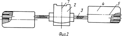
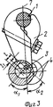
На фиг. 1 представлен гаситель вибрации, выполненный согласно изобретению, главный вид, перпендикулярно проводам (кабелям) линии; на фиг. 2 - то же, вид сверху; на фиг. 3 - вид по А-А на фиг. 1. In FIG. 1 shows a vibration damper, made according to the invention, the main view, perpendicular to the wires (cables) of the line; in FIG. 2 - the same, top view; in FIG. 3 is a view along AA in FIG. one.
Гаситель вибрации для проводов 1 воздушных линий электропередачи или самонесущих волокнно-оптических кабелей 1 линий связи состоит из плашки-зажима 2, гибко-упругого элемента (стального каната) 3 и грузов 4, которые выполняются в виде полых цилиндрических стаканов. The vibration damper for wires 1 of overhead power lines or self-supporting fiber optic cables 1 of the communication lines consists of a die-
Плашка-зажим 2 закрепляется посередине стального каната 3 и к проводу (канату) 1 линии, а концы каната 3 заделываются в грузы 4. The die-
Канат 3, состоящий из сердечника и повивов из высокопрочной стали, закрепляется в грузах 4 с некоторым смещением (эксцентриситетом) относительно их продольной оси 5. Эксцентриситет ("е") гибко-упругого элемента 3 определяется из такого соотношения: е=(1/2oC1/3) • rгруз., где rгруз. - наружный радиус грузов (цилиндрических стаканов) 4. Кроме того, эксцентриситет ("e1") внутренних цилиндрических полостей 6 в стаканах 4 определяется по такому соотношению: е = 1/5 • rгруз.The
Стальной канат 3 выполняется с верхним повивом, состоящим из спиралей, которые навиваются на его сердечник с некоторым натягом, величина которого рассчитывается из отношения d1/dk - 0,82 oC 0,85, где d1 - диаметр спирали наруженого повива каната 3, а dk- диаметр сердечника каната 3.
Грузы 4 смещены относительно вертикальной оси 7 гасителя на углы α1 и α2 (в обе стороны от вертикальной оси 7). Величины этих углов определяются следующим образом: α1= +(1/6 ÷ 1/3)•π, α2= -(1/6 ÷ 1/3)•π.The
Указанные выше соотношения выбираются экспериментально и теоретическими расчетами, при этом конечной целью экспериментов и расчетов является достижение необходимого уровня гасящей способности гасителя. The above ratios are chosen experimentally and theoretically, with the ultimate goal of the experiments and calculations is to achieve the necessary level of quenching capacity of the quencher.
Гаситель вибрации работает следующим образом. The vibration damper operates as follows.
С помощью плашки-зажима 2 гаситель устанавливается на провода (кабели) 1 линий на определенных (расчетных) расстояниях от точки крепления изолирующей подвески, обеспечивая защиту проводов (кабелей) от повреждений в результате вибрации за счет разности резонансных частот вибрационных колебаний грузов и проводов (кабелей), при этом амплитуды вибрации проводов (кабелей) линий снижаются в несколько раз. Количество устанавливаемых гасителей вибрации зависит от характера местности, по которой проходит линия: на ровной или малопересеченной местности без древесной или кустарниковой растительности гасителей устанавливается больше, а на сильно пересеченной, застроенной местности или в лесных массивах - меньше. Using the clamp-
Предлагаемый гаситель вибрации по сравнению с известными техническими решениями аналогичного назначения имеет следующие преимущества: более высокие частотно-вибрационные характеристики; оптимальная гасящая способность колебаний как проводов, так и самонесущих волоконно-оптических кабелей линий; простота конструкции и технологии изготовления и как следствие этого доступная стоимость гасителя. The proposed vibration damper in comparison with the known technical solutions for a similar purpose has the following advantages: higher frequency-vibration characteristics; optimal damping ability of vibrations of both wires and self-supporting fiber-optic cable lines; simplicity of design and manufacturing technology and, as a result, the affordable cost of the damper.
Claims (1)
e = (1/2 oC 1/3) x rг р у з .,
где e - эксцентриситет гибко-упругого элемента,
rг р у з . - наружный радиус грузов, а эксцентриситет e1 внутренних цилиндрических полостей в грузах равен e1 = 1/5 х rг р у з ., при этом верхний повив гибко-упругого элемента выполнен в виде спиралей, смонтированных на сердечнике гибко-упругого элемента с натягом, определяемым из соотношения
d1 / dk = 0,82 - 0,85,
где d1 - диаметр спирали;
dk - диаметр сердечника гибко-упругого элемента,
причем углы α1 и α2 смещения грузов относительно вертикальной оси гасителя составляют α1= +(1/6 ÷ 1/3)•π, α2= -(1/6 ÷ 1/3)•πоVibration absorber for overhead power lines wires and self-supporting fiber-optic cables of communication lines, containing a flexible-elastic element made in the form of a core and windings of high-strength steel, at the ends of which weights are fixed, and a die-clamp, one end fixed in the middle of the flexible-elastic element, and another - on the wire (cable), characterized in that the flexible-elastic element is fixed in loads with an eccentricity e, the value of which is selected from the following relation
e = (1/2 o C 1/3) xr y g r h. ,
where e is the eccentricity of the flexible elastic element,
r g r u z . - an outer radius of goods, and the eccentricity e 1 cylindrical internal cavity in loads equal to e 1 = 1/5 x r y g r h. while the upper winding of the flexible-elastic element is made in the form of spirals mounted on the core of the flexible-elastic element with an interference fit, determined from the relation
d 1 / d k = 0.82 - 0.85,
where d 1 is the diameter of the spiral;
d k - the diameter of the core of the flexible elastic element,
moreover, the angles α 1 and α 2 of the displacement of the cargo relative to the vertical axis of the damper are α 1 = + (1/6 ÷ 1/3) • π, α 2 = - (1/6 ÷ 1/3) • π
Priority Applications (1)
| Application Number | Priority Date | Filing Date | Title |
|---|---|---|---|
| RU96124034A RU2107373C1 (en) | 1996-12-24 | 1996-12-24 | Vibration damper |
Applications Claiming Priority (1)
| Application Number | Priority Date | Filing Date | Title |
|---|---|---|---|
| RU96124034A RU2107373C1 (en) | 1996-12-24 | 1996-12-24 | Vibration damper |
Publications (2)
| Publication Number | Publication Date |
|---|---|
| RU2107373C1 true RU2107373C1 (en) | 1998-03-20 |
| RU96124034A RU96124034A (en) | 1998-08-27 |
Family
ID=20188375
Family Applications (1)
| Application Number | Title | Priority Date | Filing Date |
|---|---|---|---|
| RU96124034A RU2107373C1 (en) | 1996-12-24 | 1996-12-24 | Vibration damper |
Country Status (1)
| Country | Link |
|---|---|
| RU (1) | RU2107373C1 (en) |
Cited By (6)
| Publication number | Priority date | Publication date | Assignee | Title |
|---|---|---|---|---|
| RU2180765C1 (en) * | 2000-07-03 | 2002-03-20 | Закрытое акционерное общество "Электросетьстройпроект" | Vibration damper |
| RU2185699C1 (en) * | 2001-04-19 | 2002-07-20 | Закрытое акционерное общество "Электросетьстройпроект" | Multifrequency vibration damper |
| RU2190288C1 (en) * | 2001-10-04 | 2002-09-27 | Никифоров Евгений Павлович | Method for protecting conductors and ground wires of overhead power transmission lines against fatigue vibration damage at their exit from suspension clamp |
| RU2249284C1 (en) * | 2003-08-18 | 2005-03-27 | Дубинич Любовь Аркадьевна | Unified vibration damper |
| RU2262173C2 (en) * | 2000-07-14 | 2005-10-10 | Далханти Индастриз Пти Лимитед | Vibration damper for overhead power transmission lines |
| RU2575918C2 (en) * | 2014-06-09 | 2016-02-27 | Закрытое акционерное общество "Научно-технический центр "Электросети" | Universal wind oscillation damper (versions) |
Citations (2)
| Publication number | Priority date | Publication date | Assignee | Title |
|---|---|---|---|---|
| US3400209A (en) * | 1966-04-06 | 1968-09-03 | Furukawa Electric Co Ltd | Aeolian vibration damper |
| US4159393A (en) * | 1976-07-09 | 1979-06-26 | Dulmison Australia Pty Ltd | Vibration damper |
-
1996
- 1996-12-24 RU RU96124034A patent/RU2107373C1/en active
Patent Citations (2)
| Publication number | Priority date | Publication date | Assignee | Title |
|---|---|---|---|---|
| US3400209A (en) * | 1966-04-06 | 1968-09-03 | Furukawa Electric Co Ltd | Aeolian vibration damper |
| US4159393A (en) * | 1976-07-09 | 1979-06-26 | Dulmison Australia Pty Ltd | Vibration damper |
Non-Patent Citations (1)
| Title |
|---|
| 3. Изолирующая подвеска проводов воздушных линий электропередачи и открытых распределительных устройств./ Каталог. М.: Внешторгиздат, 1979, изд. N 56006 Э, с.155, рис.146. * |
Cited By (6)
| Publication number | Priority date | Publication date | Assignee | Title |
|---|---|---|---|---|
| RU2180765C1 (en) * | 2000-07-03 | 2002-03-20 | Закрытое акционерное общество "Электросетьстройпроект" | Vibration damper |
| RU2262173C2 (en) * | 2000-07-14 | 2005-10-10 | Далханти Индастриз Пти Лимитед | Vibration damper for overhead power transmission lines |
| RU2185699C1 (en) * | 2001-04-19 | 2002-07-20 | Закрытое акционерное общество "Электросетьстройпроект" | Multifrequency vibration damper |
| RU2190288C1 (en) * | 2001-10-04 | 2002-09-27 | Никифоров Евгений Павлович | Method for protecting conductors and ground wires of overhead power transmission lines against fatigue vibration damage at their exit from suspension clamp |
| RU2249284C1 (en) * | 2003-08-18 | 2005-03-27 | Дубинич Любовь Аркадьевна | Unified vibration damper |
| RU2575918C2 (en) * | 2014-06-09 | 2016-02-27 | Закрытое акционерное общество "Научно-технический центр "Электросети" | Universal wind oscillation damper (versions) |
Similar Documents
| Publication | Publication Date | Title |
|---|---|---|
| US4388800A (en) | Method of manufacturing an optical fibre cable | |
| EP0240165B1 (en) | Optical fiber cable | |
| US3659034A (en) | Self-damping bundle conductor spacer | |
| RU2107373C1 (en) | Vibration damper | |
| US4469756A (en) | Method of and apparatus for forming an outwardly projecting bulge in a steel wire strand for forming an anchor in concrete | |
| US4549035A (en) | Aerodynamic damper for suppressing galloping in overhead transmission lines | |
| US3432610A (en) | Vibration dampers for suspended members | |
| CA2108059A1 (en) | Vibration Resistant Overhead Electrical Cable | |
| US3662084A (en) | Vibration damper | |
| GB2299444A (en) | Overhead cable | |
| US2279625A (en) | Vibration damping tie wire | |
| US4568794A (en) | Gap type ACSR conductor with supporting structure and method of forming same | |
| RU2180765C1 (en) | Vibration damper | |
| EP1315263B1 (en) | Vibration damper | |
| RU2249893C1 (en) | Ice and conductor vibration limiter for overhead power transmission lines | |
| RU96124034A (en) | VIBRATION Muffler | |
| US3406513A (en) | Dead end | |
| RU2185699C1 (en) | Multifrequency vibration damper | |
| SU1696785A1 (en) | Vibration insulator | |
| RU2228567C1 (en) | Multifrequency vibration damper | |
| SU1410194A2 (en) | Stator of liquid-cooled electric machine | |
| RU2058641C1 (en) | Spiral-type supporting clamp | |
| RU2249284C1 (en) | Unified vibration damper | |
| SU1456997A1 (en) | Wire for overhead power lines | |
| SU1315689A1 (en) | Shock absorber |