RU2104907C1 - Brace for binding pressed bale, package consisting of pressed bale and brace devices for making of brace and method of measuring wire tension - Google Patents
Brace for binding pressed bale, package consisting of pressed bale and brace devices for making of brace and method of measuring wire tension Download PDFInfo
- Publication number
- RU2104907C1 RU2104907C1 RU94004983A RU94004983A RU2104907C1 RU 2104907 C1 RU2104907 C1 RU 2104907C1 RU 94004983 A RU94004983 A RU 94004983A RU 94004983 A RU94004983 A RU 94004983A RU 2104907 C1 RU2104907 C1 RU 2104907C1
- Authority
- RU
- Russia
- Prior art keywords
- screed
- bale
- wire
- wavy
- brace
- Prior art date
Links
Images

Classifications
-
- B—PERFORMING OPERATIONS; TRANSPORTING
- B65—CONVEYING; PACKING; STORING; HANDLING THIN OR FILAMENTARY MATERIAL
- B65D—CONTAINERS FOR STORAGE OR TRANSPORT OF ARTICLES OR MATERIALS, e.g. BAGS, BARRELS, BOTTLES, BOXES, CANS, CARTONS, CRATES, DRUMS, JARS, TANKS, HOPPERS, FORWARDING CONTAINERS; ACCESSORIES, CLOSURES, OR FITTINGS THEREFOR; PACKAGING ELEMENTS; PACKAGES
- B65D63/00—Flexible elongated elements, e.g. straps, for bundling or supporting articles
- B65D63/10—Non-metallic straps, tapes, or bands; Filamentary elements, e.g. strings, threads or wires; Joints between ends thereof
- B65D63/12—Joints produced by deformation or tying of ends of elements
-
- B—PERFORMING OPERATIONS; TRANSPORTING
- B21—MECHANICAL METAL-WORKING WITHOUT ESSENTIALLY REMOVING MATERIAL; PUNCHING METAL
- B21F—WORKING OR PROCESSING OF METAL WIRE
- B21F1/00—Bending wire other than coiling; Straightening wire
- B21F1/04—Undulating
-
- B—PERFORMING OPERATIONS; TRANSPORTING
- B21—MECHANICAL METAL-WORKING WITHOUT ESSENTIALLY REMOVING MATERIAL; PUNCHING METAL
- B21D—WORKING OR PROCESSING OF SHEET METAL OR METAL TUBES, RODS OR PROFILES WITHOUT ESSENTIALLY REMOVING MATERIAL; PUNCHING METAL
- B21D13/00—Corrugating sheet metal, rods or profiles; Bending sheet metal, rods or profiles into wave form
- B21D13/02—Corrugating sheet metal, rods or profiles; Bending sheet metal, rods or profiles into wave form by pressing
-
- B—PERFORMING OPERATIONS; TRANSPORTING
- B65—CONVEYING; PACKING; STORING; HANDLING THIN OR FILAMENTARY MATERIAL
- B65D—CONTAINERS FOR STORAGE OR TRANSPORT OF ARTICLES OR MATERIALS, e.g. BAGS, BARRELS, BOTTLES, BOXES, CANS, CARTONS, CRATES, DRUMS, JARS, TANKS, HOPPERS, FORWARDING CONTAINERS; ACCESSORIES, CLOSURES, OR FITTINGS THEREFOR; PACKAGING ELEMENTS; PACKAGES
- B65D63/00—Flexible elongated elements, e.g. straps, for bundling or supporting articles
- B65D63/02—Metallic straps, tapes, or bands; Joints between ends thereof
-
- B—PERFORMING OPERATIONS; TRANSPORTING
- B65—CONVEYING; PACKING; STORING; HANDLING THIN OR FILAMENTARY MATERIAL
- B65D—CONTAINERS FOR STORAGE OR TRANSPORT OF ARTICLES OR MATERIALS, e.g. BAGS, BARRELS, BOTTLES, BOXES, CANS, CARTONS, CRATES, DRUMS, JARS, TANKS, HOPPERS, FORWARDING CONTAINERS; ACCESSORIES, CLOSURES, OR FITTINGS THEREFOR; PACKAGING ELEMENTS; PACKAGES
- B65D63/00—Flexible elongated elements, e.g. straps, for bundling or supporting articles
- B65D63/10—Non-metallic straps, tapes, or bands; Filamentary elements, e.g. strings, threads or wires; Joints between ends thereof
-
- B—PERFORMING OPERATIONS; TRANSPORTING
- B65—CONVEYING; PACKING; STORING; HANDLING THIN OR FILAMENTARY MATERIAL
- B65D—CONTAINERS FOR STORAGE OR TRANSPORT OF ARTICLES OR MATERIALS, e.g. BAGS, BARRELS, BOTTLES, BOXES, CANS, CARTONS, CRATES, DRUMS, JARS, TANKS, HOPPERS, FORWARDING CONTAINERS; ACCESSORIES, CLOSURES, OR FITTINGS THEREFOR; PACKAGING ELEMENTS; PACKAGES
- B65D85/00—Containers, packaging elements or packages, specially adapted for particular articles or materials
- B65D85/07—Containers, packaging elements or packages, specially adapted for particular articles or materials for compressible or flexible articles
-
- Y—GENERAL TAGGING OF NEW TECHNOLOGICAL DEVELOPMENTS; GENERAL TAGGING OF CROSS-SECTIONAL TECHNOLOGIES SPANNING OVER SEVERAL SECTIONS OF THE IPC; TECHNICAL SUBJECTS COVERED BY FORMER USPC CROSS-REFERENCE ART COLLECTIONS [XRACs] AND DIGESTS
- Y10—TECHNICAL SUBJECTS COVERED BY FORMER USPC
- Y10T—TECHNICAL SUBJECTS COVERED BY FORMER US CLASSIFICATION
- Y10T24/00—Buckles, buttons, clasps, etc.
- Y10T24/14—Bale and package ties, hose clamps
- Y10T24/1457—Metal bands
- Y10T24/148—End-to-end integral band end connection
-
- Y—GENERAL TAGGING OF NEW TECHNOLOGICAL DEVELOPMENTS; GENERAL TAGGING OF CROSS-SECTIONAL TECHNOLOGIES SPANNING OVER SEVERAL SECTIONS OF THE IPC; TECHNICAL SUBJECTS COVERED BY FORMER USPC CROSS-REFERENCE ART COLLECTIONS [XRACs] AND DIGESTS
- Y10—TECHNICAL SUBJECTS COVERED BY FORMER USPC
- Y10T—TECHNICAL SUBJECTS COVERED BY FORMER US CLASSIFICATION
- Y10T24/00—Buckles, buttons, clasps, etc.
- Y10T24/14—Bale and package ties, hose clamps
- Y10T24/149—Wire
Abstract
Description
Изобретение относится к стяжке для обвязки тюков, таких как кипы хлопка, которые имеют тенденцию расширяться вдоль основной оси. В соответствии с настоящим изобретением стяжка тюка изготавливается таким образом, что она имеет по меньшей мере один волнистый участок, вдоль которого стяжка может выпрямляться и поглощать силы растяжения. Изобретение относится также к упаковке, состоящей из такого тюка и такой стяжки. Изобретение относится далее к устройству для изготовления проволоки с таким волнистым участком. The invention relates to a tie for tying bales, such as cotton bales, which tend to expand along the main axis. According to the present invention, the bale screed is made in such a way that it has at least one wavy portion along which the screed can straighten and absorb tensile forces. The invention also relates to a package consisting of such a bale and such a tie. The invention further relates to a device for making wire with such a wavy portion.
Технические требования, предъявляемые к материалам для упаковки хлопка, периодически утверждаются Упаковочным комитетом хлопкоперерабатывающей промышленности /JCIBPC/. В соответствии с техническими условиями JCIBPC за 1992 год, аттестованными материалами для изготовления стяжек для тюков являются холоднокатанная стальная проволока, обладающая большим усилием на разрыв, которую можно использовать с соединениями типа жесткого затвора, соединениями типа контролируемого сдвига, соединениями шпоночного типа, а также стальная проволока по ASTM A 510-82 с использованием замковых соединений и соединений типа скруток. Specifications for cotton packaging materials are periodically approved by the Cotton Packaging Industry Committee / JCIBPC /. In accordance with JCIBPC specifications for 1992, certified materials for making bale ties are cold-rolled steel wire with a high tensile force that can be used with rigid shutter type joints, controlled shear joints, keyway joints, and steel wire according to ASTM A 510-82 using castle joints and twist joints.
Примеры обвязочных лент из стальной проволоки с соединениями типа контролируемого сдвига представлены в патенте США N 4466353 /автор Huson/ и патенте США N 4501356 /авторы Urban et al./. Примеры стяжек из стальной проволоки с соединениями шпоночного типа представлены в патенте США N 4156385 /авторы Lems et al./, патенте США N 4226007 /автор Duenser/ и патенте США N 4228565 /авторы Lems et al./. Примеры стяжек из стальной проволоки с соединениями замкового типа представлены в патенте США N 3949450 /автор Bailly/ и патенте США N 4070733 /автор Simich/. Examples of steel wire strapping tapes with controlled shear type joints are presented in US Pat. No. 4,466,353 / Huson / and US Pat. No. 4,501,356 / Urban et al./. Examples of steel wire ties with keyed joints are shown in US Pat. No. 4,156,385 / Lems et al ./, US Pat. No. 4,226,007 / Duenser / and US Pat. No. 4,228,565 / Lems et al ./. Examples of steel wire couplers with lock-type joints are presented in US Pat. No. 3,949,450 (author Bailly) and US Pat. No. 4,070,733 / author Simich /.
Обычно кипу из хлопка спрессовывают вдоль основной оси, и она стремится расширяться в первую очередь вдоль основной оси, которая является вертикальной осью в контексте упомянутых технических условий. В указанном тюке вдоль основной оси на стяжку могут прикладываться силы напряжения до 1800 фунтов /≈ 784 кг/. Однако такой тюк стремится расширяться как минимум вдоль других осей, которые являются ортогональными друг другу и основной оси. Usually a bale of cotton is pressed along the main axis, and it tends to expand primarily along the main axis, which is the vertical axis in the context of the mentioned technical conditions. In this bale, stresses up to 1800 pounds / ≈ 784 kg / can be applied to the screed along the main axis. However, such a bale tends to expand at least along other axes that are orthogonal to each other and to the main axis.
В технических условиях JCIBPC 1992 года для стяжек из проволоки при использовании в устройствах Gin Standart и Gin Universal Densitybales указывается, что проволока для стяжки должна иметь номер не меньше чем 9, что усилие на разрыв проволоки должно составлять не менее 3400 фунтов /≈ 1481 кг/, а прочность на разрыв в месте соединения, если оно расположено на верху тюка, должно составлять не менее 2100 фунтов /около 915 кг/; если же места соединения расположены сбоку тюка, то усилие на разрыв проволоки должно составлять не менее 3200 фунтов /около 1394 кг/, а прочность на разрыв в месте соединения не должна быть меньше 3040 фунтов /около 1324 кг/. Эти технические условия определяют, в каком случае использовать замковое соединение, в каком соединение типа скрутки. Номинальный диаметр стальной проволоки номер 9 составляет 0,1483 дюйма /около 0,3767 см/. The 1992 JCIBPC Specification for Wire Ties when used in Gin Standart and Gin Universal Densitybales devices states that the wire for the coupler must have a number of at least 9, and that the tensile force of the wire must be at least 3400 lbs / ≈ 1481 kg / and the tensile strength at the junction, if located on the top of the bale, should be at least 2100 pounds / about 915 kg /; if the junctions are located on the side of the bale, then the tensile strength of the wire should be at least 3200 pounds / about 1394 kg /, and the tensile strength at the junction should not be less than 3040 pounds / about 1324 kg /. These specifications determine in which case to use a lock joint, in which a twist joint. The nominal diameter of steel wire number 9 is 0.1483 inches / about 0.3767 cm /.
Как указывалось ранее, настоящее изобретение позволяет эффективно использовать стяжку из проволоки с меньшим номером путем уменьшения силы напряжения, прикладываемой к узлам такой стяжки со стороны тюка. As mentioned earlier, the present invention allows the efficient use of a tie with a lower wire number by reducing the voltage applied to the nodes of such a tie from the side of the bale.
В патенте США N 3088397 /авторы Martin et al./ описывается устройство для формирования на стальной обвязочной ленте поперечного рифления по мере того, как проволока пропускается через строповочную машину, при этом каждый кусок обвязочной ленты, который пропускают через машину, гофрируется или на нем создается рельеф по всей длине. Как указывается, каждый кусок обвязочной ленты обладает, таким образом, способностью упруго деформироваться, противодействуя разбуханию узла, стянутого лентой, такого как рулон бумаги или пакет. US Pat. No. 3,088,397 / Martin et al ./ describes a device for forming transverse corrugation on a steel strapping tape as the wire passes through a sling machine, each piece of strapping tape that is passed through the machine is corrugated or created on it relief along the entire length. As indicated, each piece of strapping tape thus has the ability to elastically deform, counteracting the swelling of the knotted tape, such as a paper roll or bag.
В настоящем изобретении заявляется стяжка с улучшенной структурой для обвязки спрессованного тюка, такого как кипа хлопка, который имеет в основном прямоугольную форму и определяется взаимно перпендикулярными осями, в том числе основной осью, и который имеет тенденцию расширяться вдоль основной оси. В соответствии с настоящим изобретением стяжка изготавливается таким образом, чтобы на ней образовался по меньшей мере один волнистый участок, вдоль которого стяжка может выпрямляться, поглощая часть сил натяжения, которые прикладываются на стяжку со стороны тюка, обвязанного такой стяжкой. The present invention claims a tie with an improved structure for tying a compressed bale, such as a bale of cotton, which is generally rectangular in shape and defined by mutually perpendicular axes, including the main axis, and which tends to expand along the main axis. In accordance with the present invention, the screed is made in such a way that at least one wavy portion is formed on it, along which the screed can be straightened, absorbing some of the tension forces that are applied to the screed from the side of the bale tied with such a screed.
Стяжка имеет достаточную длину и достаточную гибкость, чтобы ее можно было обвязать вокруг тюка. Противоположные концы могут соединяться друг с другом с образованием узла после того, как стяжка обвязана вокруг тюка. Проволока подготавливается таким образом, чтобы на ней сформировался по меньшей мере один волнистый участок, расположенный между двумя, обычно прямыми, участками стяжки и характеризующийся наличием ряда синусоидальных изгибов, вдоль которого стяжка может выпрямляться, поглощая силы напряжения, приложенные к стяжке со стороны тюка, обвязанного такой стяжкой. Волнистая поверхность является средством предотвращения приложения к стяжке максимальных сил напряжения по месту узлов, образованных на противоположных концах стяжки. The screed is long enough and flexible enough to be tied around a bale. Opposite ends can connect to each other to form a knot after the tie is tied around a bale. The wire is prepared in such a way that at least one wavy section is formed on it, located between two, usually straight, sections of the screed and characterized by a number of sinusoidal bends, along which the screed can straighten, absorbing the stresses applied to the screed from the side of the bundle tied such a screed. The corrugated surface is a means of preventing the application of maximum tension forces to the screed in place of the nodes formed at opposite ends of the screed.
Предпочтительно, стяжку выполняют таким образом, чтобы на ней были именно два волнистых участка, которые вместе составляют существенно менее половины от общей длины проволоки. Более того, желательно, чтобы волнистые поверхности располагались на некотором расстоянии друг от друга и были расположены таким образом, чтобы быть параллельными основной оси после того, как стяжка обвязана вокруг тюка. Preferably, the screed is made so that it has exactly two wavy sections, which together comprise substantially less than half of the total length of the wire. Moreover, it is desirable that the wavy surfaces are located at some distance from each other and are positioned so as to be parallel to the main axis after the tie is tied around the bale.
Стяжка предпочтительно изготавливается из предварительно разрезанной стальной проволоки, которой придают форму таким образом, чтобы образовались участки с волнистой поверхностью и соединительные образования на каждом ее конце. Соединительные образования способны соединяться друг с другом с образованием узла. Стяжка может также представлять собой предварительно разрезанную стальную ленту, которую формуют таким образом, чтобы она имела участок с волнистой поверхностью, а для образования узла может использоваться соединение типа жесткого затвора, соединение с контролируемым сдвигом и соединение шпоночного типа. The screed is preferably made of pre-cut steel wire, which is shaped in such a way as to form sections with a wavy surface and connecting formations at each end thereof. Connective formations are able to connect with each other with the formation of a node. The screed can also be a pre-cut steel strip, which is molded so that it has a section with a wavy surface, and a rigid shutter type joint, controlled shear joint, and key type joint can be used to form a knot.
В общем случае, как и в известных стяжках, предельная прочность места соединения меньше, чем величина прочности на разрыв недеформированной части стяжки. В настоящем изобретении предполагается, что в том случае, если стяжку формуют таким образом, чтобы образовать по меньшей мере один участок с волнистой поверхностью, то стяжка обладает величиной прочности на разрыв, меньшей чем предельная прочность недеформированной части стяжки, но большей чем величина прочности на разрыв в месте узла известного типа. In the general case, as in the known screeds, the ultimate strength of the joint is less than the tensile strength of the undeformed part of the screed. The present invention assumes that if the screed is molded so as to form at least one section with a corrugated surface, the screed has a tensile strength less than the ultimate strength of the undeformed portion of the screed, but greater than the tensile strength in place of a node of a known type.
В одном из рассмотренных примеров, в котором каждая стяжка изготавливается из предварительно нарезанной стальной проволоки, узел имеет предельную прочность, которая приблизительно составляет 65% от предельной прочности недеформированной части стяжки, а предельная прочность проволоки, на которой имеется по меньшей мере один участок с волнистой поверхностью, составляет приблизительно от 85 до 90% от предельной прочности недеформированной части проволоки. In one of the considered examples, in which each screed is made of pre-cut steel wire, the assembly has ultimate strength, which is approximately 65% of the ultimate strength of the undeformed part of the coupler, and the ultimate strength of the wire, on which there is at least one section with a wavy surface , is approximately 85 to 90% of the ultimate strength of the undeformed part of the wire.
В данном случае термины "прочность на разрыв" и "предельная прочность" используются как синонимы для обозначения усилия на разрыв, которое /во время проведения испытаний на разрыв/ определяется как отношение максимально допустимой нагрузки к первоначальной площади сечения /см. J.R. Davis, Ed., ASM Materials Engineering Dictionary, ASM International, 1992/. In this case, the terms "tensile strength" and "ultimate strength" are used as synonyms for tensile strength, which / during tensile tests / is defined as the ratio of the maximum allowable load to the original cross-sectional area / cm. J.R. Davis, Ed., ASM Materials Engineering Dictionary, ASM International, 1992 /.
В настоящем изобретении заявляется также улучшенная упаковка, состоящая из спрессованного тюка, указанного выше типа, и стяжки, которая имеет достаточную длину и гибкость, чтобы ее можно было обвязать вокруг тюка и стянуть. На противоположных концах стяжки формируется соединение. В соответствии с настоящим изобретением стяжку выполняют таким образом, чтобы на ней сформировать два участка с волнистой поверхностью, каждый из которых располагается между в основном прямыми участками стяжки. Каждый из участков с волнистой поверхностью характеризуется наличием ряда синусоидальных неровностей. Участки с волнистой поверхностью вместе составляют не более половины от общей длины стяжки. Стяжка может вытягиваться по этим участкам с волнистой поверхностью, поглощая силы натяжения, прикладываемые к стяжке со стороны тюка в процессе того, как тюк расширяется главным образом вдоль основной оси. The present invention also claims an improved package consisting of a compressed bale of the above type and a tie that is of sufficient length and flexibility to be tied around the bale and pulled together. A connection is formed at opposite ends of the screed. In accordance with the present invention, the screed is made so as to form two sections with a wavy surface on it, each of which is located between the generally straight sections of the screed. Each of the sections with a wavy surface is characterized by the presence of a number of sinusoidal irregularities. Sites with a wavy surface together make up no more than half of the total length of the screed. The screed can be stretched over these areas with a wavy surface, absorbing the tensile forces applied to the screed from the side of the bale as the bale expands mainly along the main axis.
Настоящее изобретение позволяет эффективно измерить величину натяжения, прикладываемого к проволоке, имеющей участок с волнистой поверхностью, который характеризуется наличием ряда синусоидальных неровностей. После того как к проволоке приложена первая нагрузка, которую она выдерживает, не начиная растягиваться, нагрузку снимают, а затем вновь прикладывают нагрузку, которая превышает величину первой нагрузки, и измеряют степень удлинения проволоки. The present invention allows to effectively measure the amount of tension applied to a wire having a section with a wavy surface, which is characterized by the presence of a number of sinusoidal irregularities. After the first load is applied to the wire, which it can withstand without starting to stretch, the load is removed, and then the load is applied again, which exceeds the value of the first load, and the degree of elongation of the wire is measured.
В настоящем изобретении заявляется также устройство для формования проволоки таким образом, что на ней создается ряд синусоидальных неровностей. Устройство состоит из двух приспособлений для растягивания, а именно верхнего крепежного приспособления и нижнего крепежного приспособления, и набора верхних формирующих валков и набора нижних формирующих валков. The present invention also claims a device for forming a wire in such a way that a number of sinusoidal irregularities are created on it. The device consists of two devices for stretching, namely, the upper mounting device and the lower mounting device, and a set of upper forming rolls and a set of lower forming rolls.
Верхнее крепежное приспособление соединяется с нижним крепежным приспособлением таким образом, чтобы сохранялась возможность относительного перемещения приспособлений между открытым положением и закрытым положением. Верхнее крепежное приспособление соприкасается с нижним крепежным приспособлением в закрытом положении и отстоит на некотором расстоянии от нижнего крепежного приспособления в открытом положении. The upper fastener is connected to the lower fastener so that the relative movement of the devices between the open position and the closed position is maintained. The upper fastener is in contact with the lower fastener in the closed position and is separated by a certain distance from the lower fastener in the open position.
Каждый из верхних формующих валков соединяется с верхним крепежным приспособлением таким образом, что он свободно вращается вокруг верхнего вала, который имеет поперечное направление. Верхние валы, вокруг которых могут вращаться верхние формующие валки, расположены в одной плоскости и отстоят друг от друга на одинаковом расстоянии. Each of the upper forming rolls is connected to the upper mounting device so that it freely rotates around the upper shaft, which has a transverse direction. The upper shafts around which the upper forming rolls can rotate are located in the same plane and are at the same distance from each other.
Каждый из верхних формующих валков имеет окружную канавку, которая приспособлена для приема проволоки. Предпочтительно верхнее крепежное приспособление установлено на оси относительно нижнего крепежного приспособления так, что оно может вращаться вокруг поперечной оси, которая отстоит от набора верхних формующих валков. Each of the upper forming rolls has a circumferential groove that is adapted to receive wire. Preferably, the upper mounting device is mounted on an axis relative to the lower mounting device so that it can rotate around a transverse axis that is spaced from the set of upper forming rolls.
Каждый из нижних формующих валков установлен относительно нижнего крепежного приспособления таким образом, что он может свободно вращаться вокруг нижнего вала, простирающегося в поперечном направлении. Нижние валы, вокруг которых могут вращаться нижние формующие валки, расположены в одной плоскости и отстоят друг от друга на одинаковом расстоянии. Каждый из нижних формующих валков имеет окружную канавку, приспособленную для приема проволоки. Each of the lower forming rolls is mounted relative to the lower mounting device so that it can freely rotate around the lower shaft, which extends in the transverse direction. The lower shafts around which the lower forming rolls can rotate are located in the same plane and are equally spaced from each other. Each of the lower forming rolls has a circumferential groove adapted to receive wire.
Верхние и нижние формующие валки расположены таким образом, что их окружные канавки образуют синусообразный путь в том случае, когда крепежные приспособления находятся в закрытом положении. Верхние и нижние формующие валки представляют собой приспособление для формования проволоки, которая поступает на их цилиндрические пазы, так что на проволоке образуются серии синусоидальных неровностей, которые в основном соответствуют синусоидальному пути при относительном перемещении крепежных приспособлений в закрытое положение. The upper and lower forming rolls are arranged in such a way that their circumferential grooves form a sinusoidal path when the fastening devices are in the closed position. The upper and lower forming rolls are a device for forming a wire that enters their cylindrical grooves, so that a series of sinusoidal irregularities are formed on the wire, which generally correspond to a sinusoidal path when the fasteners are moved relative to the closed position.
Эти и другие цели, особенности и преимущества настоящего изобретения становятся очевидными из последующего описания примеров осуществления изобретения, которые приводятся вместе с соответствующими фигурами. These and other objectives, features and advantages of the present invention become apparent from the following description of embodiments of the invention, which are given together with the corresponding figures.
Фиг. 1 - общий вид спрессованного тюка, например кипа хлопка, охваченного множеством одинаковых стяжек, изготовленных из предварительно нарезанной стальной проволоки, содержащей участки с волнистой поверхностью по изобретению. Фрагментарно показаны перемещающиеся валки обычного пресса, используемого для образования тюка. FIG. 1 is a general view of a compressed bale, for example, a bale of cotton covered by a plurality of identical ties made of pre-cut steel wire containing sections with a corrugated surface according to the invention. Moving rolls of a conventional press used to form a bale are fragmented.
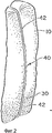
Фиг. 2 - фрагмент фиг. 1, на котором изображена одна из стяжек, используемых для обвязки тюка. FIG. 2 is a fragment of FIG. 1, which depicts one of the ties used to tie a bale.
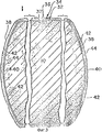
Фиг. 3 - фрагмент поперечного сечения тюка, изображенного на фиг. 1. FIG. 3 is a fragment of the cross section of the bale of FIG. one.
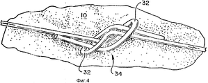
Фиг. 4 - еще более увеличенный фрагмент противоположных концов одной из стяжек, которые используются для обвязки тюка, изображенного на фиг. 1, 2 и 3. Как видно из фиг. 4, замковые приспособления на противоположных концах стяжки скрепляются друг с другом с образованием узла. FIG. 4 is an even larger enlarged fragment of the opposite ends of one of the ties that are used to tie the bale of FIG. 1, 2 and 3. As can be seen from FIG. 4, the locking devices at the opposite ends of the coupler are fastened together to form a knot.
Фиг. 5 - фрагмент, аналогичный фиг. 2, но показывающий стяжку, изготовленную из предварительно нарезанной стальной обвязочной ленты, имеющей участок с волнистой поверхностью по настоящему изобретению, вместе с уплотнением на противоположных концах ленты. Изображенная стяжка представляет собой одну из аналогичных стяжек, используемых для обвязки тюка. FIG. 5 is a fragment similar to FIG. 2, but showing a screed made from a pre-cut steel strapping tape having a portion with a corrugated surface of the present invention, together with a seal at opposite ends of the tape. The screed shown is one of the similar screeds used to tie the bale.
Фиг. 6 - фрагмент поперечного разреза тюка, представленного на фиг. 5. FIG. 6 is a fragment of a cross section of the bale of FIG. 5.
На фиг. 7 - фрагмент стяжки, используемой для обвязки тюка, изображенного на фиг. 5 и 6. In FIG. 7 is a fragment of a tie used to tie the bale of FIG. 5 and 6.
Фиг. 8 и 9 - вид спереди устройства по изобретению, состоящего из рассмотренных верхних валков и нижних валков, которое используется для изготовления обвязочной проволоки, содержащей участки с волнистой поверхностью. На фиг. 8 устройство показано в открытом положении. На фиг. 9 устройство показано в закрытом положении. FIG. 8 and 9 are a front view of the device according to the invention, consisting of the considered upper rolls and lower rolls, which is used to make a strapping wire containing sections with a wavy surface. In FIG. 8, the device is shown in the open position. In FIG. 9, the device is shown in the closed position.
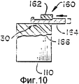
Фиг. 10 - поперечный разрез по 10-10 на фиг. 9 в направлении, указанном стрелками. FIG. 10 is a cross section through 10-10 of FIG. 9 in the direction of the arrows.
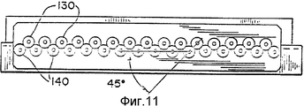
Фиг. 11 - схематично часть устройства, аналогичного устройству, представленному на фиг. 8 и 9, но имеющего другое расположение верхних и нижних валков. На фиг. 11 аппарат показан в закрытом положении. FIG. 11 is a schematic part of a device similar to the device shown in FIG. 8 and 9, but having a different arrangement of the upper and lower rolls. In FIG. 11 the apparatus is shown in the closed position.
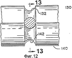
Фиг. 12 - сильно увеличенный, схематичный вид поперечного разреза по 12-12 на фиг. 9 в направлении, указанном стрелками. FIG. 12 is a greatly enlarged, schematic cross-sectional view along 12-12 of FIG. 9 in the direction of the arrows.
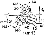
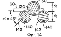
Фиг. 13 и 14 - в несколько меньшем масштабе аналогичные разрезы, показывающие три возможных варианта взаимного расположения указанных верхних и нижних валков вместе с проволокой. На фиг. 14 показан разрез по 14-14 на фиг. 13 в направлении, указанном стрелками. Расположение узлов на фиг. 14 соответствует расположению узлов на фиг. 8 и 9. FIG. 13 and 14 are, on a slightly smaller scale, similar sections showing three possible options for the relative positioning of these upper and lower rolls together with the wire. In FIG. 14 shows a section through 14-14 in FIG. 13 in the direction of the arrows. The location of the nodes in FIG. 14 corresponds to the arrangement of the nodes in FIG. 8 and 9.
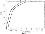
Фиг. 15 - графически показывает характеристики растяжения двух стяжек с волнистыми участками, на которые вначале подают нагрузку 1500 фунтов /около 680 кг/, затем загрузку снимают и вновь подают нагрузку 2200 фунтов /около 998 кг/. FIG. 15 - graphically shows the tensile characteristics of two screeds with wavy sections, which are initially supplied with a load of 1,500 pounds / about 680 kg /, then the load is removed and the load is supplied again with 2,200 pounds / about 998 kg /.
Предпочтительные варианты выполнения изобретения. Preferred Embodiments of the Invention
Как показано на фиг. 1, 2, 3 и 4, тюк хлопка 10 спрессовывают по вертикали в обычном прессе 12 для формирования тюков, который имеет верхнюю фиксированную пластину 14 и нижнюю подвижную пластину 16. Поскольку тюк 10 спрессовывают в прессе 12 по вертикали, то тюк 10 стремится расшириться в первую очередь вдоль вертикальной оси, которая в контексте настоящего изобретения принимается за главную ось тюка 10. С другой стороны, вдоль поперечной и продольной осей тюк 10 расширяется незначительно. На верхней пластине 14 располагаются на одинаковом расстоянии канавки 18, а на нижней пластине 16 имеется ряд аналогичных канавок 20. Показано восемь канавок 18 и восемь канавок 20. С помощью этих канавок, пока тюк 10 находится под прессом 12, можно вручную обвязать тюк 10 восемью стяжками 30. As shown in FIG. 1, 2, 3 and 4, a bale of
Каждая стяжка 30 имеет достаточную длину /например, 89 дюймов, примерно 226 см/ и достаточную гибкость, чтобы эту стяжку можно было бы вручную обвязать вокруг тюка 10, пока тюк 10 находится под прессом 12. Each
Каждую стяжку изготавливают отдельно из предварительно нарезанной стальной проволоки. Как указано на фиг. 3 и 4, каждая стяжка на концах согнута так, что образуется замковое приспособление 32 петельного типа, которое широко используется с проволочными стяжками, как это, например, описано в патенте США N 4070733 /автор Simich/, содержание которого включается в данное описание путем ссылки. Замковые приспособления 32 каждой стяжки соответствуют друг другу и могут образовывать узел 34 известного типа в том случае, когда такая стяжка 30 обвязывается вокруг тюка 10, пока тюк 10 остается под прессом 12. В общем случае, как и в проволочных стяжках, известных ранее, такой узел имеет предел прочности, меньший чем предел прочности недеформированной части стальной проволоки, которая используется для изготовления стяжек 30. В настоящем изобретении предполагается, что могут быть использованы замковые приспособления /не показаны/ другого типа, отличные от петельного типа. Each screed is made separately from pre-cut steel wire. As indicated in FIG. 3 and 4, each coupler at the ends is bent so that a loop-
Как показано, стяжки 30 преимущественно обвязываются вокруг тюка 10 так, чтобы узлы 34 оказывались на верху 36 тюка, после того, как тюк 10 высвобождается из-под пресса 12. Однако стяжки 30 могут обвязываться вокруг тюка 10 таким образом, чтобы узлы 34 оказывались по одну из сторон 38 тюка 10, преимущественно ближе к верху 36. Стяжки можно перемещать вокруг тюка 10 так, чтобы узлы 34 оказались на верху 36 тюка, прежде чем тюк 10 высвободится из-под пресса 12. As shown, the
В одном из рассмотренных примеров, в котором используется стальная проволока номер 10 с номинальным диаметром 0,1350 дюйма /0,343 см/, предельная нагрузка которой в недеформированном состоянии составляет приблизительно 2850 фунтов /около 1293 кг/, максимальное относительное удлинение 2%, а состав соответствует AISI C 1070, такой узел 34 имеет предельную нагрузку, равную приблизительно 1850 фунтов /около 839 кг/, что соответствует приблизительно 65% от величины предельной нагрузки недеформированной части такой проволоки. In one of the examples considered, in which
Такой тюк 10 может оказывать вдоль основной оси давление до 1800 фунтов /около 816 кг/ на каждую стяжку 30. Однако, как уже отмечалось ранее, настоящее изобретение позволяет эффективно использовать стяжку 30 по предыдущему примеру /см. предыдущий параграф/, не подвергая узел 34, образованный на ее концах, силам напряжения, величина которых приближается к пределу прочности такого узла 34. Such a
В соответствии с настоящим изобретением каждая стяжка 30 изготавливается таким образом, чтобы на ней сформировалось два волнистых участка 40, каждый из которых располагается между двумя в основном прямыми участками 42 каждой стяжки 30. Каждый волнистый участок 40 характеризуется набором одинаковых синусоидальных неровностей 44. Волнистые участки 40 каждой стяжки 30 вместе составляют существенно менее половины общей длины стяжки 30. В одном из рассмотренных примеров каждая стяжка 30 имеет общую длину около 89 дюймов /226 см/, а каждый волнистый участок имеет кажущуюся длину приблизительно 10 дюймов /25,4 см/. Волнистые участки 40 уменьшают общую длину каждой стяжки 30 приблизительно от 0,25 дюйма /0,635 см/ до 0,375 дюйма /0,953 см/. Когда каждая стяжка 30 обвязывается вокруг тюка 10, в основном прямые участки 42 могут быть слегка согнуты, как показано на чертеже. In accordance with the present invention, each screed 30 is made so that two
Поскольку они отстоят друг от друга на стяжке 30, волнистые участки 40 расположены таким образом, что они оказываются параллельными основной оси, когда такая стяжка 30 обвязывается вокруг тюка 10, а узел 34 такой стяжки оказывается на верху 36 тюка 10. Таким образом, после того, как тюк 10 высвобождается из-под пресса 12, каждая стяжка 30 может выпрямляться вдоль волнистого участка 40, поглощая часть сил натяжения, которые прикладываются к такой стяжке 30 со стороны тюка 10, когда тюк 10 стремится расшириться в первую очередь вдоль основной оси. Since they are spaced apart on the
В уже рассмотренном примере, в котором используется стальная проволока номер 10 с номинальным диаметром 0,1350 дюйма /0,343 см/, предельная нагрузка которой в недеформированном состоянии составляет приблизительно 2850 фунтов /около 1293 кг/, максимальное относительное удлинение 2%, а состав соответствует AISI C 1060, стальная проволока готовится таким образом, чтобы волнистые участки имели предельную прочность, соответствующую приблизительно от 85% до приблизительно 95% предельной прочности недеформированной части стальной проволоки. In the example already considered, in which
Под нагрузкой прямой участок стальной проволоки ведет себя подобно очень жесткой пружине до тех пор, пока проволока не начинает растягиваться при достижении предела текучести. Таким образом, если приложенная, а затем снятая нагрузка не превышает его предела текучести, прямой участок стремится спружинить до своей исходной длины. Наоборот, волнистый участок стальной проволоки начинает распрямляться сразу после приложения нагрузки. Таким образом, если к нему приложить напряжение, а затем снять его, то волнистый участок стремится спружинить, но не до своей исходной длины. Under load, the straight section of the steel wire behaves like a very stiff spring until the wire begins to stretch when the yield point is reached. Thus, if the applied and then removed load does not exceed its yield strength, the straight section tends to spring to its original length. On the contrary, the corrugated portion of the steel wire begins to straighten immediately after application of the load. Thus, if a voltage is applied to it, and then it is removed, the wavy section tends to spring, but not to its original length.
После однократного приложения и снятия нагрузки волнистый участок проявляет свойство памяти о максимальной нагрузке, которая была приложена к данному участку. Таким образом, после того, как стяжка снята с тюка, можно с помощью управляемой компьютером нагрузочной машины измерить с точностью приблизительно ± 5% максимальное напряжение, которое испытывает стяжка, имеющая волнистый участок, со стороны тюка. На фиг. 15 представлен график, на котором показано удлинение /"смещение"/ двух образцов, каждый из которых представляет собой волнистый отрезок стальной проволоки и был нагружен с усилием приблизительно 1500 фунтов /около 680 кг/, а затем был вновь нагружен /в той же нагрузочной машине/ с растягивающим усилием /"нагрузкой"/ приблизительно 2200 фунтов /около 998 кг/. After a single application and removal of the load, the wavy section exhibits the memory property of the maximum load that was applied to this section. Thus, after the screed has been removed from the bale, it is possible, using a computer-controlled loading machine, to measure with accuracy approximately ± 5% the maximum stress experienced by the screed having a wavy portion from the side of the bale. In FIG. 15 is a graph showing the elongation / “displacement” of two samples, each of which is a corrugated section of steel wire and was loaded with a force of approximately 1,500 pounds / about 680 kg /, and then was again loaded / in the same loading machine / with tensile force / "load" / approximately 2200 pounds / about 998 kg /.
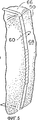
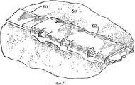
Как показано на фиг. 5, 6 и 7, тюк 50 из хлопка, аналогичный тюку 10 из хлопка и спрессованный в обычном прессе /не показан/, аналогичном прессу 12, обвязан стяжками 60 /показана только одна/ другой конструкции, которые также входят в объем притязаний по настоящему изобретению. Поскольку тюк 50 сжимается по вертикали, то он стремится расшириться в первую очередь вдоль вертикальной оси, которая является основной осью тюка 50 в контексте настоящего изобретения. As shown in FIG. 5, 6 and 7, a
Каждая стяжка 60 состоит из предварительно нарезанной стальной обвязочной ленты, концы которой после того, как она обвязывает тюк 50, перекрываются и закрепляются с помощью заклепки 62, которая накладывается на перекрывающиеся концы ленты 62, образуя узел 64. Предел прочности узла 64 меньше, чем предел прочности недеформированной части стальной лены 62. За исключением случаев, рассматриваемых в данном описании, каждая стяжка аналогична стальным ленточным стяжкам, которые выпускаются фирмой "ITW Signode" /отделение фирмы Illinois Tool Works Inc./ Гленвью, штат Иллинойс. Each
В настоящем изобретении предполагается, что для формирования узла на перекрывающихся концах такой обвязочной ленты можно по выбору использовать соединение с контролируемым сдвигом, описанное в патенте США N 4466535 /автор Huson/ и в патенте США N 4501356 /авторы Vrban et al./, или соединение замкового типа, описанное в патенте США N 4156385 /авторы Lans et al./, патенте США N 4226007 /автор Duenser/ и патенте США N 4228565 /авторы Lems et al./. In the present invention, it is contemplated that, for forming a knot at the overlapping ends of such a strapping tape, a shear controlled connection described in US Pat. No. 4,466,535 / Huson / and US Pat. No. 4,501,356 / Vrban et al./, or castle type described in US patent N 4156385 / authors Lans et al./, US patent N 4226007 / author Duenser / and US patent N 4228565 / authors Lems et al./.
Как показано, стяжки 60 преимущественно обвязываются вокруг тюка 50 так, чтобы узлы 64 таких стяжек 60 оказывались на верху 66 тюка 50, после того, как тюк 50 высвобождается из-под упомянутого ранее пресса. Однако каждая стяжка 60 может обвязываться вокруг тюка 50 таким образом, чтобы узел 64 такой стяжки 60 оказывался по одну из сторон 68 тюка 50, преимущественно ближе к верху 66. Стяжки 60 можно перемещать вокруг тюка 50 так, чтобы узлы 64 оказались на верху 66 тюка, прежде чем высвободиться из-под указанного пресса. As shown, the
В соответствии с настоящим изобретением каждая стяжка 60 изготавливается таким образом, чтобы на ней сформовать два волнистых участка 70, каждый из которых располагается между двумя в основном прямыми участками 72 каждой стяжки 60. Каждый волнистый участок 70 характеризуется набором одинаковых синусоидальных неровностей 74. Волнистые участки 70 каждой стяжки 60 вместе составляют значительно меньше половины общей длины такой стяжки 60. В одном из рассмотренных примеров волнистые участки составляют вместе приблизительно одну пятую часть общей длины стяжки 60. Когда каждая стяжка 60 обвязывается вокруг тюка 50, в основном прямые участки 72 могут быть слегка согнуты, как показано на фигуре. In accordance with the present invention, each screed 60 is made in such a way as to form two
Поскольку они отстоят друг от друга на стяжке 60, волнистые участки 70 располагаются таким образом, что они оказываются параллельными основной оси, когда такая стяжка 60 обвязывается вокруг тюка 50, а узел 64 такой стяжки 60 оказывается на верху 66 тюка 50. Таким образом, после того, как тюк 50 высвобождается из указанного пресса, каждая стяжка 60 может вытягиваться вдоль ребристого участка 70, поглощая часть сил напряжения, которые прикладываются к такой стяжке 60 со стороны тюка 50, когда тюк 50 стремится расшириться главным образом вдоль основной оси. Since they are spaced apart on the
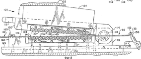
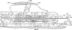
Как показано на фиг. 8 и 9, а также на других фигурах, устройство 100 по настоящему изобретению может быть использовано для изготовления стяжки 30 из стальной проволоки, имеющей волнистый участок 40 и замковое приспособление 32 на противоположных концах такой стяжки 30. Устройство 100 может использоваться вместе с обычным прессом, таким как валковый пресс, который состоит из подвижной верхней станины 102 и неподвижной нижней станины 104. За исключением станин 102 и 104, которые показаны схематично, сам пресс не показан. В таком прессе верхняя станина 102 может двигаться вверх и вниз. As shown in FIG. 8 and 9, as well as in other figures, the
Устройство 100 состоит из протяженного основания 106, на котором закрепляются два крепежных устройства, а именно верхнее крепежное устройство 108 и нижнее крепежное устройство 110. Верхнее крепежное устройство 108 присоединяется к нижнему крепежному устройству 110 с помощью соосного стержня 112, направленного вдоль поперечной оси, вокруг которой верхнее крепежное устройство 108 может вращаться, что и обеспечивает соосное перемещение блоков устройств 108 и 110 друг относительно друга между открытым положением и закрытым положением. Соосный стержень 112 подвижно закрепляется у одного конца 114 верхнего крепежного устройства 108 и у другого конца 116 нижнего крепежного устройства 110. К другому концу 120 верхнего крепежного устройства 108 рядом с другим концом 122 нижнего крепежного устройства 110 прикреплена рукоятка 118. The
На фиг. 8 основание 106 и крепежные устройства 108 и 110 изображены между станинами 102 и 104 в открытом положении, при котором верхнее крепежное устройство 108 смещено на острый угол по отношению к нижнему крепежному устройству 110. На фиг. 9 основание 106 и крепежные устройства 108 и 110 изображены между станинами 102 и 104 в закрытом положении, при котором верхнее крепежное устройство 108 располагается рядом с нижним крепежным устройством 110 параллельно ему. In FIG. 8, the
Как показано на фиг. 8 и 9, основание 106 располагается на нижней станине 104. Кулачковая структура 124, которая крепится к верхнему крепежному устройству 108, приспособлена для закрепления верхней станины 102. As shown in FIG. 8 and 9, the
Предусматривается набор из семнадцати одинаковых верхних формующих валков 130. Каждый из верхних формующих валков 130 располагается на верхнем крепежном устройстве 108 таким образом, чтобы они свободно вращались вокруг верхнего вала, который располагается поперечно. Верхние валы, вокруг которых вращаются верхние формующие валки 130, копланарны и отстоят равномерно друг от друга. Верхние формующие валки 130 прикрепляются к верхнему крепежному устройству 108 таким образом, что соосный стержень 112 располагается между верхними формующими валками 130 и концом 114 верхнего крепежного устройства 108. Каждый из формующих валков 130 имеет окружную канавку 132, приспособленную для приема стальной проволоки стяжки 30, и которая имеет форму, соответствующую в общем случае половине сечения проволоки номер 10. Как указано на фиг. 12, окружные канавки 132 имеют круглое поперечное сечение. A set of seventeen identical
Предусматривается набор из аналогичных восемнадцати одинаковых нижних формующих валков 140. Каждый из нижних формующих валков 140 располагается на нижнем крепежном устройстве 110 таким образом, чтобы они свободно вращались вокруг нижнего вала, который располагается поперечно. Нижние валы, вокруг которых вращаются нижние формующие валки 140, копланарны и отстоят равномерно друг от друга. Нижние формующие валки 140 прикрепляются к нижнему устройству 110 таким образом, что соосный стержень 112 располагается между нижними формующими валками 140 и концом 116 нижнего крепежного устройства 110. Каждый из нижних формующих валков 140 имеет цилиндрический паз 142, который приспособлен для приема стальной проволоки стяжки 30 и который имеет форму, соответствующую в общем случае половине сечения проволоки номер 10. Как показано на фиг. 12, окружные канавки 142 имеют полукруглое поперечное сечение. A set of eighteen identical lower forming
Установочный стержень 150, имеющий увеличенную головку 152, жестко прикрепляется к нижнему крепежному устройству 110 недалеко от конца 116. Установочный стержень изготовлен таким образом, что он позволяет надеть вручную на увеличенную головку 152 замковое приспособление 32 на одно из противоположных концов стяжки 30, и эта головка закрепляет и удерживает этот конец стяжки 30 в устройстве 100. The mounting
Запорное приспособление 160 устанавливается на нижнем крепежном устройстве 110 недалеко от конца 116. Запорное приспособление 160 состоит из направляющей 162, которая жестко закрепляется на нижнем крепежном устройстве 110, и запора 164, который крепится подвижно на направляющей 162. Запорное устройство изготовлено таким образом, что оно удерживает внутри канавки 166 нижнего крепежного устройства часть стальной проволоки растяжки 30, замковое приспособление 32 которой надето на увеличенную головку 152 установочного стержня 150. The
Формующие валки 130 и 140 установлены таким образом, что окружные канавки 132 и 142 образуют синусоидальную дорожку для стальной проволоки стяжки 30, если крепежные приспособления 108 и 110 находятся в закрытом состоянии. Формующие валки 130 и 140 являются средством образования на стальной проволоке, поступающей в окружные канавки 132 и 142, ряда синусоидальных неровностей, которые в основном соответствуют синусоидальной дорожке, которая образуется при относительном перемещении крепежных приспособлений 108 и 110 в закрытое положение. The forming rolls 130 and 140 are mounted so that the
В первоначальный момент, как показано на фиг. 8, с помощью рукоятки 118 верхняя станина 102 поднимается, верхнее крепежное приспособление 108 и верхние формующие валки 130 поворачиваются так, что крепежные приспособления 108 и 110 оказываются в закрытом положении. Далее закрепляется стальная проволока, на которой нужно сформовать участок с волнистой поверхностью 40, так что замковое приспособление 32 на одном из противоположных концов стяжки 30 надевается на увеличенную головку 152 установочного стержня 150, а стальная проволока стяжки 30 захватывается окружными канавками 142 нижних формующих валков 140, и часть стальной проволоки захватывается запорным приспособлением 160. После этого верхняя плита опускается, так что начинает поворачиваться верхнее крепежное приспособление 106 вместе с формующими валками 130, и крепежные приспособления 108 и 110 оказываются в закрытом положении, при этом окружные канавки 132 верхних формующих валков захватывают стальную проволоку. Таким образом, формующие валки 130 и 140 воздействуют на стальную проволоку и формуют на ней ряд синусоидальных неровностей, которые создают на стяжке 30 участок с ребристой поверхностью 40. At the initial moment, as shown in FIG. 8, with the aid of the handle 118, the
Шаг и амплитуда серии синусоидальных неровностей зависят от формовочного угла α и от формовочного диаметра df. Как показано на фиг. 13 и 14, величина формовочного угла определяется центральной осью недеформированной части стальной проволоки, захваченной окружными канавками 142 нижних формующих валков 140, и линией, проходящей через одну из изображенных нижних осей нижних формующих валков 140 и через верхнюю ось следующего из верхних формующих валков 130, когда крепежные приспособления 108 и 110 находятся в закрытом положении. Как показано на фигуре, формующий диаметр df представляет собой диаметр каждого из формующих валков 130 и 140 в том случае, когда окружные канавки 132 и 142 являются наиболее глубокими. The pitch and amplitude of a series of sinusoidal irregularities depend on the molding angle α and on the molding diameter df. As shown in FIG. 13 and 14, the value of the forming angle is determined by the central axis of the undeformed portion of the steel wire gripped by the
Формовочный угол предпочтительно выбирают в интервале приблизительно от 45o до приблизительно 60o. Формовочный диаметр предпочтительно выбирают в интервале приблизительно от 0,375 дюймов /около 0,953 см/ до приблизительно 0,5 дюймов /1,27 см/.The forming angle is preferably selected in the range of from about 45 ° to about 60 ° . The molding diameter is preferably selected in the range of from about 0.375 inches / about 0.953 cm / to about 0.5 inches / 1.27 cm /.
В описанные выше предпочтительные варианты осуществления изобретения могут быть внесены различные модификации, которые не выходят за рамки объема притязаний по настоящему изобретению. Various modifications may be made to the preferred embodiments described above that are within the scope of the present invention.
Claims (13)
Applications Claiming Priority (2)
| Application Number | Priority Date | Filing Date | Title |
|---|---|---|---|
| US1837893A | 1993-02-16 | 1993-02-16 | |
| US08/018,378 | 1993-02-16 |
Publications (2)
| Publication Number | Publication Date |
|---|---|
| RU94004983A RU94004983A (en) | 1996-06-27 |
| RU2104907C1 true RU2104907C1 (en) | 1998-02-20 |
Family
ID=21787612
Family Applications (1)
| Application Number | Title | Priority Date | Filing Date |
|---|---|---|---|
| RU94004983A RU2104907C1 (en) | 1993-02-16 | 1994-02-15 | Brace for binding pressed bale, package consisting of pressed bale and brace devices for making of brace and method of measuring wire tension |
Country Status (19)
| Country | Link |
|---|---|
| US (3) | US5477724A (en) |
| EP (1) | EP0611706B1 (en) |
| JP (2) | JPH06255669A (en) |
| KR (1) | KR940019557A (en) |
| CN (1) | CN1093331A (en) |
| AT (1) | ATE149957T1 (en) |
| AU (1) | AU663428B2 (en) |
| BR (1) | BR9400497A (en) |
| CA (1) | CA2113880A1 (en) |
| DE (1) | DE69401968T2 (en) |
| DK (1) | DK0611706T3 (en) |
| EG (1) | EG20232A (en) |
| ES (1) | ES2098801T3 (en) |
| GR (1) | GR3022794T3 (en) |
| HK (1) | HK132097A (en) |
| NZ (1) | NZ250868A (en) |
| RU (1) | RU2104907C1 (en) |
| TW (1) | TW275610B (en) |
| ZA (1) | ZA94390B (en) |
Cited By (1)
| Publication number | Priority date | Publication date | Assignee | Title |
|---|---|---|---|---|
| RU2727489C1 (en) * | 2017-03-14 | 2020-07-21 | Отикер Швайц Аг | Device for force control during fixation of coupling band |
Families Citing this family (12)
| Publication number | Priority date | Publication date | Assignee | Title |
|---|---|---|---|---|
| US6035691A (en) * | 1999-08-10 | 2000-03-14 | Lin; Ruey-Mo | Adjustable rod bending device for a corrective spinal rod which is used in a surgical operation |
| US6616090B1 (en) | 2000-03-31 | 2003-09-09 | L&P Property Management Company | Wire supply control assembly for feeding wire |
| US6553900B1 (en) * | 2000-03-31 | 2003-04-29 | L&P Property Management Company | Three-part wire return for baling machine |
| US6711994B1 (en) | 2000-03-31 | 2004-03-30 | L & P Property Management Company | Wire-tie pull pins |
| US6975911B2 (en) | 2001-07-31 | 2005-12-13 | L&P Property Management Company | Operator input interface for baling machine |
| US7497158B2 (en) | 2001-07-31 | 2009-03-03 | L&P Property Management Company | Baling machine with narrow head wire feeder |
| US6637324B2 (en) | 2001-07-31 | 2003-10-28 | L & P Property Management Company | Wide aperture wire tracking for baling machine |
| US6633798B2 (en) * | 2001-07-31 | 2003-10-14 | L & P Property Management Company | Control system for baling machine |
| US6628998B2 (en) | 2001-07-31 | 2003-09-30 | L & P Property Management Company | Operator input interface for baling machine |
| US6705214B1 (en) | 2001-07-31 | 2004-03-16 | L&P Property Management Company | Automatic cotton baler with tilt-out heads |
| JP3893334B2 (en) * | 2002-08-23 | 2007-03-14 | ファナック株式会社 | Multi-system numerical controller |
| EP3209576B1 (en) | 2014-10-23 | 2020-11-25 | Thomas & Betts International LLC | Anti-slip tie with wave springs |
Family Cites Families (39)
| Publication number | Priority date | Publication date | Assignee | Title |
|---|---|---|---|---|
| US5005A (en) * | 1847-03-06 | Iien ry | ||
| US758820A (en) * | 1903-04-10 | 1904-05-03 | James P Chaplin | Hoop. |
| US1235353A (en) * | 1914-05-29 | 1917-07-31 | Acme Steel Goods Company | Box-strapping. |
| US2085082A (en) * | 1932-10-15 | 1937-06-29 | Republic Steel Corp | Method for bundling bale ties and the like |
| FR769832A (en) * | 1934-03-08 | 1934-09-03 | Mauser Maschb Gmbh | Machine for folding the edges and corrugating the envelopes of sheet metal containers |
| US2183169A (en) * | 1938-11-05 | 1939-12-12 | Prentice G E Mfg Co | Method of making fasteners |
| US2290608A (en) * | 1939-02-18 | 1942-07-21 | Richard K Stevens | Foil crumpling method and apparatus |
| US2575899A (en) * | 1940-12-23 | 1951-11-20 | Gerrard Steel Strapping Compan | Automatic wire tying machine |
| US2356936A (en) * | 1941-06-09 | 1944-08-29 | Case Co J I | Bale tie |
| US2666004A (en) * | 1950-06-06 | 1954-01-12 | Gerrard & Co A J | Steel strapping and shield |
| US2599427A (en) * | 1951-05-26 | 1952-06-03 | Int Harvester Co | Method of bundling spring harrow tines |
| US2915003A (en) * | 1956-11-13 | 1959-12-01 | Signode Steel Strapping Co | Power strapping machine |
| US2914643A (en) * | 1957-04-29 | 1959-11-24 | Hy Sil Mfg Company | Wire feeder mechanism |
| US2915004A (en) * | 1958-04-09 | 1959-12-01 | Signode Steel Strapping Co | Hydraulic tensioning control for power strapping machines |
| US3088397A (en) * | 1960-07-19 | 1963-05-07 | Signode Steel Strapping Co | Power strapping machine |
| US3235071A (en) * | 1962-09-19 | 1966-02-15 | Interlake Steel Corp | Corrugated binder strap |
| FR2050185A1 (en) * | 1969-06-03 | 1971-04-02 | Combustible Nucleaire | Deforming plates into undulations |
| US4302979A (en) * | 1971-06-16 | 1981-12-01 | Dykmans Maximiliaan J | Means and techniques useful in stressing cable |
| US3777557A (en) * | 1971-11-05 | 1973-12-11 | Greenwood Mills Corp | Strand tester |
| US3853546A (en) * | 1972-08-09 | 1974-12-10 | F Werner | Force gage |
| DE2257063C3 (en) * | 1972-11-21 | 1975-08-07 | Siemens Ag, 1000 Berlin Und 8000 Muenchen | Method for manufacturing a tantalum dry electrolytic capacitor |
| DE2256983C2 (en) * | 1972-11-21 | 1975-02-13 | Titan Verpackungssysteme Gmbh, 5830 Schwelm | Lifting strap for heavy loads |
| PL87170B1 (en) * | 1974-02-06 | 1976-06-30 | ||
| US3921799A (en) * | 1974-08-16 | 1975-11-25 | Signode Corp | Fixed length loop-forming strap and overlap joint therefor |
| US4070733A (en) * | 1976-07-26 | 1978-01-31 | A. J. Gerrard & Company | Pre-notched tieing wires |
| US4228565A (en) * | 1978-08-17 | 1980-10-21 | Signode Corporation | Strap for forming a readily disengageable anti-reverse sealless strap connection |
| US4156385A (en) * | 1978-08-17 | 1979-05-29 | Signode Corporation | Method of readily disengaging anti-reverse sealless strap connection to facilitate reusing strap |
| US4226007A (en) * | 1979-03-16 | 1980-10-07 | Signode Corporation | Sealless strap connection |
| US4235114A (en) * | 1979-04-02 | 1980-11-25 | Ledex, Inc. | Material testing device |
| US4245512A (en) * | 1979-06-18 | 1981-01-20 | Levi Strauss & Co. | Fabric stretch testing device |
| JPS577331A (en) * | 1980-06-16 | 1982-01-14 | Mitsubishi Heavy Ind Ltd | Simultaneous bending method |
| JPS5720532U (en) * | 1980-07-09 | 1982-02-02 | ||
| JPS5873063A (en) * | 1981-10-28 | 1983-05-02 | Nec Corp | Magnetic disc device |
| US4501356A (en) * | 1982-12-29 | 1985-02-26 | Signode Corporation | Slip seal joint for strap |
| US4466535A (en) * | 1982-12-29 | 1984-08-21 | Signode Corporation | Slip seal joint for strap |
| AU561706B2 (en) * | 1983-04-01 | 1987-05-14 | Foster Wheeler Energy Corporation | Forming elongated helical shapes from wire |
| US4643016A (en) * | 1986-03-14 | 1987-02-17 | Barberine Frank G | Slat bending tool |
| JPS63194823A (en) * | 1987-02-06 | 1988-08-12 | Showa Aircraft Ind Co Ltd | Forming press die for corrugated sheet |
| DE4106266A1 (en) * | 1991-02-28 | 1992-09-10 | Airbus Gmbh | METHOD FOR MEASURING ROPE TENSION AND DEVICE FOR ITS IMPLEMENTATION |
-
1994
- 1994-01-18 AU AU53836/94A patent/AU663428B2/en not_active Ceased
- 1994-01-19 ZA ZA94390A patent/ZA94390B/en unknown
- 1994-01-19 AT AT94100701T patent/ATE149957T1/en not_active IP Right Cessation
- 1994-01-19 DE DE69401968T patent/DE69401968T2/en not_active Expired - Fee Related
- 1994-01-19 ES ES94100701T patent/ES2098801T3/en not_active Expired - Lifetime
- 1994-01-19 EP EP94100701A patent/EP0611706B1/en not_active Expired - Lifetime
- 1994-01-19 DK DK94100701.5T patent/DK0611706T3/en active
- 1994-01-20 CA CA002113880A patent/CA2113880A1/en not_active Abandoned
- 1994-02-04 CN CN94101356A patent/CN1093331A/en active Pending
- 1994-02-10 BR BR9400497A patent/BR9400497A/en not_active IP Right Cessation
- 1994-02-12 EG EG8594A patent/EG20232A/en active
- 1994-02-14 NZ NZ250868A patent/NZ250868A/en unknown
- 1994-02-15 RU RU94004983A patent/RU2104907C1/en active
- 1994-02-15 KR KR1019940002803A patent/KR940019557A/en not_active Application Discontinuation
- 1994-02-15 JP JP6039354A patent/JPH06255669A/en active Pending
- 1994-03-04 TW TW083101881A patent/TW275610B/zh active
- 1994-07-12 US US08/273,680 patent/US5477724A/en not_active Expired - Fee Related
- 1994-07-12 US US08/273,679 patent/US5483837A/en not_active Expired - Fee Related
- 1994-07-12 US US08/274,118 patent/US5417320A/en not_active Expired - Fee Related
-
1996
- 1996-09-18 JP JP1996010096U patent/JP3067054U/en not_active Expired - Lifetime
-
1997
- 1997-03-13 GR GR960402883T patent/GR3022794T3/en unknown
- 1997-06-26 HK HK132097A patent/HK132097A/en not_active IP Right Cessation
Cited By (2)
| Publication number | Priority date | Publication date | Assignee | Title |
|---|---|---|---|---|
| RU2727489C1 (en) * | 2017-03-14 | 2020-07-21 | Отикер Швайц Аг | Device for force control during fixation of coupling band |
| US11054322B2 (en) | 2017-03-14 | 2021-07-06 | Oetiker Schweiz Ag | Device for monitoring force when fixing a tension clamp |
Also Published As
| Publication number | Publication date |
|---|---|
| GR3022794T3 (en) | 1997-06-30 |
| TW275610B (en) | 1996-05-11 |
| EP0611706A1 (en) | 1994-08-24 |
| US5417320A (en) | 1995-05-23 |
| BR9400497A (en) | 1994-08-23 |
| AU663428B2 (en) | 1995-10-05 |
| US5483837A (en) | 1996-01-16 |
| DE69401968D1 (en) | 1997-04-17 |
| DE69401968T2 (en) | 1997-06-26 |
| RU94004983A (en) | 1996-06-27 |
| AU5383694A (en) | 1994-09-08 |
| ZA94390B (en) | 1994-09-01 |
| CA2113880A1 (en) | 1994-08-17 |
| DK0611706T3 (en) | 1997-09-15 |
| CN1093331A (en) | 1994-10-12 |
| HK132097A (en) | 1997-10-03 |
| NZ250868A (en) | 1996-04-26 |
| EP0611706B1 (en) | 1997-03-12 |
| KR940019557A (en) | 1994-09-14 |
| EG20232A (en) | 1998-05-31 |
| ES2098801T3 (en) | 1997-05-01 |
| JPH06255669A (en) | 1994-09-13 |
| US5477724A (en) | 1995-12-26 |
| JP3067054U (en) | 2000-03-21 |
| ATE149957T1 (en) | 1997-03-15 |
Similar Documents
| Publication | Publication Date | Title |
|---|---|---|
| RU2104907C1 (en) | Brace for binding pressed bale, package consisting of pressed bale and brace devices for making of brace and method of measuring wire tension | |
| DE3918311C3 (en) | Method and device for wrapping piece goods, in particular piece goods stacks, with a stretch film hood | |
| CA1167365A (en) | Power assisted stretch wrap apparatus and process | |
| JPH0565631B2 (en) | ||
| SK90396A3 (en) | Insulating element, method and plant for producing and packaging | |
| CA2869423C (en) | Safety band longitudinal and transverse control | |
| AU721258B2 (en) | Improved puzzle-lock compression ring | |
| CA1068881A (en) | Reusable connectable strap segment within a large strap segment | |
| EA013045B1 (en) | Method and device for bundling steel coils and binding tape for this | |
| JPH10510792A (en) | Double fold insulation bat | |
| CN220595282U (en) | Efficient packaging device for woven bag production | |
| CN1193371A (en) | A machine for joing together elongated objects | |
| JPS588701Y2 (en) | Packing body made of flexible long pipes | |
| JP2611078B2 (en) | Apparatus and method for binding wire coil | |
| US2458747A (en) | Device for attaching metal baling ribbons to anchorage plates | |
| JPH04253614A (en) | Binding method for wire coil | |
| EP1264778B1 (en) | Device for the edge protection of a package for plate-like insulation elements | |
| JPH02197336A (en) | Binding wires for reinforcing steel and manufacture thereof | |
| JP3092003U (en) | Binding rebar | |
| KR960004445Y1 (en) | Fixing-clip for band | |
| DE19524456C2 (en) | Method and device for strapping compressible packages | |
| AU729721B2 (en) | Improved puzzle-lock compression ring | |
| JPH018794Y2 (en) | ||
| SU1252460A1 (en) | Method of reinforcing ferroconcrete beams | |
| JPH03617A (en) | Semi-tangible object binding method |