RU2102626C1 - Nozzle orifice - Google Patents
Nozzle orifice Download PDFInfo
- Publication number
- RU2102626C1 RU2102626C1 RU94038224A RU94038224A RU2102626C1 RU 2102626 C1 RU2102626 C1 RU 2102626C1 RU 94038224 A RU94038224 A RU 94038224A RU 94038224 A RU94038224 A RU 94038224A RU 2102626 C1 RU2102626 C1 RU 2102626C1
- Authority
- RU
- Russia
- Prior art keywords
- nozzle
- protrusion
- fuel
- valve element
- paragraphs
- Prior art date
Links
Images
Classifications
-
- F—MECHANICAL ENGINEERING; LIGHTING; HEATING; WEAPONS; BLASTING
- F04—POSITIVE - DISPLACEMENT MACHINES FOR LIQUIDS; PUMPS FOR LIQUIDS OR ELASTIC FLUIDS
- F04C—ROTARY-PISTON, OR OSCILLATING-PISTON, POSITIVE-DISPLACEMENT MACHINES FOR LIQUIDS; ROTARY-PISTON, OR OSCILLATING-PISTON, POSITIVE-DISPLACEMENT PUMPS
- F04C19/00—Rotary-piston pumps with fluid ring or the like, specially adapted for elastic fluids
-
- F—MECHANICAL ENGINEERING; LIGHTING; HEATING; WEAPONS; BLASTING
- F02—COMBUSTION ENGINES; HOT-GAS OR COMBUSTION-PRODUCT ENGINE PLANTS
- F02M—SUPPLYING COMBUSTION ENGINES IN GENERAL WITH COMBUSTIBLE MIXTURES OR CONSTITUENTS THEREOF
- F02M61/00—Fuel-injectors not provided for in groups F02M39/00 - F02M57/00 or F02M67/00
- F02M61/04—Fuel-injectors not provided for in groups F02M39/00 - F02M57/00 or F02M67/00 having valves, e.g. having a plurality of valves in series
- F02M61/08—Fuel-injectors not provided for in groups F02M39/00 - F02M57/00 or F02M67/00 having valves, e.g. having a plurality of valves in series the valves opening in direction of fuel flow
-
- F—MECHANICAL ENGINEERING; LIGHTING; HEATING; WEAPONS; BLASTING
- F02—COMBUSTION ENGINES; HOT-GAS OR COMBUSTION-PRODUCT ENGINE PLANTS
- F02M—SUPPLYING COMBUSTION ENGINES IN GENERAL WITH COMBUSTIBLE MIXTURES OR CONSTITUENTS THEREOF
- F02M61/00—Fuel-injectors not provided for in groups F02M39/00 - F02M57/00 or F02M67/00
- F02M61/04—Fuel-injectors not provided for in groups F02M39/00 - F02M57/00 or F02M67/00 having valves, e.g. having a plurality of valves in series
- F02M61/06—Fuel-injectors not provided for in groups F02M39/00 - F02M57/00 or F02M67/00 having valves, e.g. having a plurality of valves in series the valves being furnished at seated ends with pintle or plug shaped extensions
Abstract
Description
Изобретение относится к клапанно-регулируемому соплу для впрыска жидкости, в частности, к клапанно-регулируемому соплу для впрыска топлива в двигатель внутреннего сгорания. В данном описании под термином "двигатель внутреннего сгорания" следует понимать, Что он ограничивается двигателями, имеющими прерывистый цикл сгорания, такой как у возвратно-поступательных или роторных двигателей, и не включает в себя двигатели с непрерывным горением вроде турбин. The invention relates to a valve-controlled nozzle for injecting liquid, in particular, to a valve-adjustable nozzle for injecting fuel into an internal combustion engine. As used herein, the term “internal combustion engine” is understood to mean that it is limited to engines having an intermittent combustion cycle, such as for reciprocating or rotary engines, and does not include continuous combustion engines such as turbines.
Характеристики факела топлива, выходящего из сопла форсунки в двигатель внутреннего сгорания, такой как двигатель с непосредственным впрыском в камеру сгорания, оказывает большое влияние на регулирование процесса горения топлива, который, в свою очередь, влияет на устойчивость работы двигателя, эффективный расход топлива и состав отработавших газов двигателя. Для того чтобы оптимизировать эти показатели, в частности, для двигателя с воспламенением от искры, требуемые характеристики по факелу топлива, исходящему из сопла форсунки, включают в себя размеры мелких топливных капель (жидкого топлива), которые регулируются геометрией распыла и проникающей способностью топлива. Далее, по меньшей мере, при низких скоростях подачи топлива, требуется относительный по содержанию и равномерно распределенный воспламеняемый туман из паров топлива вблизи свечи зажигания двигателя. The characteristics of the fuel jet leaving the nozzle of the nozzle into an internal combustion engine, such as an engine with direct injection into the combustion chamber, have a great influence on the regulation of the fuel combustion process, which, in turn, affects the stability of the engine, effective fuel consumption and the composition of the spent engine gases. In order to optimize these indicators, in particular for a spark ignition engine, the required characteristics of the fuel jet coming from the nozzle of the nozzle include the size of small fuel droplets (liquid fuel), which are regulated by the geometry of the spray and the penetrating ability of the fuel. Further, at least at low speeds of fuel supply, a relative in content and uniformly distributed flammable fog from the fuel vapor near the engine spark plug is required.
Некоторые известные сопла форсунок, используемые для подачи топлива непосредственно в камеру сгорания двигателя, представляют собой клапанный тип с открывающимся наружу тарельчатым клапаном, они подают топливо в виде цилиндрического или расходящегося конусом факела. Свойства формы факела топлива зависят от ряда факторов, включая геометрию окна и клапана, составляющего сопло, особенно поверхности окна и клапана, непосредственно примыкающие к седлу, где окна и клапан соединяются для уплотнения, когда сопло закрыто. Как только выбрана геометрия сопла, обеспечивающая требуемые характеристики топливной форсунки и процесса сгорания, относительно малые отклонения от этой геометрии могут ухудшить эти характеристики, в частности, при низких скоростях подачи топлива. Some known nozzle nozzles used to supply fuel directly to the combustion chamber of the engine are valve type with poppet valves that open outward; they supply fuel in the form of a cylindrical or diverging cone torch. The properties of the fuel jet shape depend on a number of factors, including the geometry of the window and valve making up the nozzle, especially the surface of the window and valve directly adjacent to the seat, where the windows and valve are connected to seal when the nozzle is closed. As soon as the nozzle geometry is selected that provides the required characteristics of the fuel nozzle and the combustion process, relatively small deviations from this geometry can degrade these characteristics, in particular, at low fuel feed rates.
Налипания или наростания из твердых продуктов сгорания или иные отложения на поверхностях сопла, по которым стекает топливо, могут вредно сказываться на создании правильного распределения топлива и, следовательно, на процессе сгорания двигателя. Основной причиной наростания отложений на этих поверхностях является налипание углерода, в связанном виде, или отдельных частиц, которые получаются в результате сгорания топлива, включая неполное сгорание оставшегося топлива, осевшего на этих поверхностях между циклами впрыска. The buildup or buildup of solid combustion products or other deposits on the surfaces of the nozzle through which the fuel flows can adversely affect the creation of the correct distribution of fuel and, therefore, the combustion process of the engine. The main reason for the build-up of deposits on these surfaces is the sticking of carbon, in bonded form, or of individual particles resulting from the combustion of fuel, including incomplete combustion of the remaining fuel deposited on these surfaces between injection cycles.
Известно, что полая топливная струя, извергаемая из сопла, первоначально проходит путь, определяемый направлением выхода и скоростью выхода топлива. Известно также, что поскольку топливная струя опережает конец подачи сопла форсунки, то понижение скорости струи топлива и снижение давления, существующего в зоне, охваченной струей, непосредственно за соплом, способствует сжатию струи вовнутрь, принятому как горловина. It is known that a hollow fuel jet discharged from a nozzle initially passes a path determined by the direction of exit and the rate of exit of fuel. It is also known that since the fuel jet is ahead of the end of the nozzle nozzle, lowering the speed of the fuel jet and decreasing the pressure existing in the area covered by the jet directly behind the nozzle contributes to the compression of the jet inwards, which is accepted as the neck.
Установлено также, что возмущение топливного потока из сопла влияет на форму топливной струи, в частности, во время и после ее обжатия. Такое влияние может способствовать непредсказуемым отклонением и/или диспергирование топлива, которое в свою очередь, опережает влияние на процесс сгорания и, таким образом, вызывать увеличение расхода топлива и нежелательный уровень выброса отработавших газов, а также неустойчивость работы двигателя, особенно, на режимах низкой нагрузки. Нарушения, которые могут приводить к таким нежелательным последствиям, включают наличие вредных отложений на поверхностях, образующих выход из сопла форсунки, таких как углерод или другие связанные продукты сгорания, несоосность деталей клапана и седла форсунки или чрезмерный зазор между стержнем клапана и расточкой, по которой он перемещается для открытия и закрытия. Боковые смещения или несоосность клапана и отложения на клапане или седле, каждый из них, может в результате привести к изменениям относительной скорости потока в разных сечениях периферии сопла, вызывая, таким образом, асимметрию струи топлива. It was also established that the perturbation of the fuel flow from the nozzle affects the shape of the fuel jet, in particular, during and after its compression. Such an effect can contribute to unpredictable deviation and / or dispersion of the fuel, which, in turn, is ahead of the effect on the combustion process and, thus, cause an increase in fuel consumption and an undesirable level of exhaust emissions, as well as instability of the engine, especially at low load . Violations that can lead to such undesirable consequences include the presence of harmful deposits on surfaces that form the exit of the nozzle of the nozzle, such as carbon or other associated products of combustion, misalignment of the valve parts and the nozzle seat, or excessive clearance between the valve stem and the bore along which it moves to open and close. Lateral displacements or misalignment of the valve and deposits on the valve or seat, each of them, as a result, can lead to changes in the relative flow velocity in different sections of the periphery of the nozzle, thus causing an asymmetry of the fuel jet.
Описанные выше возмущения при подаче топлива в камеру сгорания двигателя представляются, в частности, значительными для двигателей, работающих с послойным распределением заряда, так как считается, что этот цикл благоприятен для регулирования эмиссии выхлопа на низких нагрузочных режимах. The perturbations described above when fuel is supplied to the engine’s combustion chamber are, in particular, significant for engines operating with a layered charge distribution, since it is believed that this cycle is favorable for controlling exhaust emission at low load conditions.
Задача, настоящего изобретения состоит в том, чтобы обеспечить сопло форсунки, которое будет содействовать улучшенному регулированию формы и направления струи топлива и поэтому улучшать характеристики и эффективность сопла форсунки и, соответственно, процесс сгорания. The object of the present invention is to provide a nozzle nozzle that will contribute to improved regulation of the shape and direction of the fuel jet and therefore improve the characteristics and efficiency of the nozzle nozzle and, accordingly, the combustion process.
Для решения задачи предусматривается, что сопло форсунки для двигателя внутреннего сгорания с впрыском топлива содержит сопло, через которое топливо подается к двигателю и которое имеет окно с внутренней поверхностью, и клапанный элемент, имеющий дополнительную внешнюю поверхность и выполненный подвижным относительно окна, соответственно обеспечивая проход между поверхностями для подачи топлива или плотного их прижатия, чтобы предупредить подачу топлива, характеризующееся тем, что клапанный элемент имеет выступ, выступающий за край сопла и образованный внешней тороидальной поверхностью, при этом выступ выполнен по форме и расположен так, что струя топлива, созданная топливом, истекающим из прохода, будет проходить по пути, образованному внешней тороидальной поверхностью выступа. To solve the problem, it is provided that the nozzle nozzle for an internal combustion engine with a fuel injection comprises a nozzle through which fuel is supplied to the engine and which has a window with an inner surface, and a valve element having an additional outer surface and made movable relative to the window, respectively providing a passage between surfaces for supplying fuel or tightly pressing them to prevent fuel supply, characterized in that the valve element has a protrusion protruding beyond the edge nozzle and formed by an external toroidal surface, the protrusion being made in shape and positioned so that the fuel jet created by the fuel flowing out of the passage will pass along the path formed by the external toroidal surface of the protrusion.
Более подробно, выступ выполнен по форме таким и так расположен, что струя топлива, исходящая из соплового прохода, когда сопло форсунки открыто, будет охватывать часть выступа смежно с клапанным элементом и последовательно протекать вдоль пути, образованного внешней поверхностью выступа. In more detail, the protrusion is shaped in such a way that the fuel jet emanating from the nozzle passage, when the nozzle nozzle is open, will cover part of the protrusion adjacent to the valve element and flow sequentially along the path formed by the outer surface of the protrusion.
Обычно выступ имеет круговое поперечное сечение и, предпочтительно, зауживается, по меньшей мере, от клапанного элемента к другому своему концу. Обычно горловинная часть между клапанным элементом и смежным концом выступа обеспечивает уменьшенную площадь поперечного сечения, вследствие чего уменьшается площадь, через которую тепло на выступе может передаваться на клапанный элемент и от него рассеиваться через сопло форсунки к цилиндру или головке цилиндра. Это обжатие содействует удержанию тепла на выступе, сохраняя тем самым достаточно высокую температуру выступа, чтобы дожигать углерод или другие частицы, отложенные на его поверхности. Typically, the protrusion has a circular cross section and, preferably, is narrowed at least from the valve element to its other end. Typically, the neck portion between the valve element and the adjacent end of the protrusion provides a reduced cross-sectional area, thereby reducing the area through which heat on the protrusion can be transferred to the valve element and dissipated from it through the nozzle nozzle to the cylinder or cylinder head. This compression contributes to the retention of heat on the protrusion, thereby maintaining the temperature of the protrusion sufficiently high to burn off carbon or other particles deposited on its surface.
Наличие выступа, который содействует при регулировании образуемой струи топлива, пока оно истекает из сопла форсунки, вносит значительный вклад в управление процессом сгорания и, следовательно, регулирование эмиссии выхлопных газов и эффективного расхода топлива. Выступ стабилизирует струю топлива путем обеспечения физической поверхности для направления распыла за сопло форсунки. В результате, это приводит к уменьшению бокового отклонения в колебания распыла за каждый цикл впрыска. The presence of the protrusion, which helps in regulating the fuel jet formed, while it is flowing out of the nozzle of the nozzle, makes a significant contribution to the control of the combustion process and, therefore, the regulation of exhaust emissions and efficient fuel consumption. The protrusion stabilizes the jet of fuel by providing a physical surface for directing the spray beyond the nozzle of the nozzle. As a result, this leads to a decrease in lateral deviation in spray oscillations for each injection cycle.
Наличие выступа, уходящего вниз от сопла форсунки, является эффективным для направления струи топлива, поскольку представляет собой результат начального сцепления струи с выступом, поднимающимся от естественного внутреннего сужения горловинной струи топлива на коротком расстоянии от выхода из сопла форсунки. Как только установилось такое сцепление, струя устанавливается в контакте с внешней поверхностью выступа и направляется ею благодаря эффекту Коанда. Струя затем будет следовать по пути, соответствующему внешней поверхности выступа, благодаря чему уменьшается возможность смещения струи топлива вбок вследствие неравенства давления и скоростей на противоположных сторонах струи. The presence of a protrusion extending downward from the nozzle of the nozzle is effective for directing the fuel jet, since it is the result of the initial engagement of the jet with the protrusion rising from the natural internal narrowing of the neck of the fuel jet at a short distance from the exit of the nozzle of the nozzle. As soon as such adhesion is established, the jet is installed in contact with the outer surface of the protrusion and is directed by it due to the Coanda effect. The jet will then follow a path corresponding to the outer surface of the protrusion, thereby reducing the possibility of the fuel jet moving sideways due to the inequality of pressure and speeds on opposite sides of the jet.
Следует иметь в виду, что направленность струи топлива благодаря выступу, проходящему от клапанного элемента сопла, будет содействовать единообразию в направлении потока струи топлива в камеру сгорания с учетом других факторов влияния, таких как отмечалось выше, которые могут вызывать неравномерность или отклонение струи топлива или ее частей. Направленность струи топлива может помочь исправить недостатки струи, возникающие из-за производственных изменений, включая пределы допусков и отклонения допусков. It should be borne in mind that the direction of the fuel jet due to the protrusion passing from the valve element of the nozzle will contribute to uniformity in the direction of flow of the fuel jet into the combustion chamber, taking into account other influence factors, such as noted above, which can cause unevenness or deviation of the fuel jet or its parts. The direction of the fuel jet can help correct jet flaws resulting from manufacturing changes, including tolerance limits and tolerance deviations.
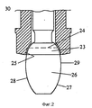
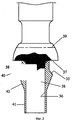
Изобретение будет проще понято из приведенного ниже описания отдельных практических устройств топливной форсунки, как это раскрыто в прилагаемых чертежах, на которых показано: фиг. 1 вид сечения части сопла топливной форсунки; фиг. 2 подобное сечение сопла топливной форсунки с альтернативной формой выступа; фиг. 3 вид части сечения клапана топливной форсунки, установленного с другой альтернативной формой выступа. The invention will be more readily understood from the following description of individual practical fuel injector devices, as disclosed in the accompanying drawings, in which: FIG. 1 is a sectional view of a portion of a nozzle of a fuel injector; FIG. 2 a similar section of a nozzle of a fuel injector with an alternative form of a protrusion; FIG. 3 is a sectional view of a valve of a fuel injector mounted with another alternative projection shape.
Сопла топливной форсунки, как показано на фиг. 1, 2 и 3 и как будет раскрыто ниже, могут быть включены в широкий круг топливных форсунок для подачи топлива в камеру сгорания двигателя. Типичные формы форсунок, в которых сопла согласно настоящему изобретению могут быть применены, раскрыты в [1, 2] оба под названием "Орбитальный двигатель" компании Pty Ltd и решение каждой из этих предыдущих заявок включено здесь в описание в качестве ссылок. Fuel nozzle nozzles as shown in FIG. 1, 2 and 3, and as will be described below, can be included in a wide range of fuel injectors for supplying fuel to the combustion chamber of the engine. Typical nozzle forms in which nozzles according to the present invention can be applied are disclosed in [1, 2] both under the name “Pty Ltd Orbiting Engine” and a solution to each of these previous applications is incorporated herein by reference.
Согласно фиг. 1, корпус 10 сопла топливной форсунки представляет собой, по существу, цилиндрическую форму, имеющую втулочную часть 11, которая предусмотрена для размещения ее в расточке, выполненной во взаимодействующей части целого узла топливной форсунки. Клапан 13 имеет головку 14 клапана и стержень 15 клапана. Стержень 15 имеет направляющую часть 18, которая соосна с возможностью расположения в расточке 12 корпуса 10. Стержень 15 выполнен полым так, чтобы топливо могло подаваться через него, а отверстия 16 предусмотрены в стенке стержня 15 для того, чтобы позволить топливу проходить через внутренность стержня 15 в расточку 12. According to FIG. 1, the fuel injector nozzle body 10 is a substantially cylindrical shape having a sleeve portion 11 that is provided for placement in a bore formed in an interacting portion of an entire fuel nozzle assembly. The valve 13 has a valve head 14 and a valve stem 15. The rod 15 has a guide portion 18, which is coaxial with the possibility of location in the bore 12 of the housing 10. The rod 15 is hollow so that fuel can be supplied through it, and holes 16 are provided in the wall of the rod 15 in order to allow fuel to pass through the inside of the rod 15 boring 12.
Клапанная головка 14 представляет собой часть сферической формы и вставляется в окно 17, предусмотренное в конце корпуса 10 и сообщающееся с расточкой 12. Стенка окна 17 выполнена в виде усеченного конуса, чтобы он мог соединяться по седловой линии 20 клапанной головки 14, когда последний находится в закрытом положении. The valve head 14 is a part of a spherical shape and is inserted into the window 17 provided at the end of the housing 10 and communicating with the bore 12. The wall of the window 17 is made in the form of a truncated cone so that it can be connected along the saddle line 20 of the valve head 14 when the latter is in closed position.
Направляющий струю выступ 30 выполнен совместно с головкой 14 клапана 13 и соединяется с ней с помощью шейки 31, которая по существу, представляет собой поперечное сечение, уменьшенное до сечения направляющего струю выступа 30, ограничить тепловой поток от направляющего выступа и таким образом повысить его температуру, как было отмечено ранее. Направляющий струю выступ представляет собой усеченную коническую форму с большим поперечным сечением, примыкающим к шейке 31. The
Диаметр края 32 направляющего струю выступа, вблизи клапанной головки, подобран так, что струя топлива, истекающая из клапана, когда он открыт, будет следовать по пути, определенному внешней поверхностью 33 направляющего выступа. Чтобы достичь этого конца, диаметр верхнего конца 32 определяется, по большей части, экспериментально, доводя присоединение внутреннего пограничного слоя топливной струи до внешней поверхности 33 направляющего выступа так, что топливная струя будет следовать по пути, дополнительному к поверхности 33. Конфигурация внешней поверхности выступа может быть также подобрана технологической ориентацией топлива в требуемом направлении, несоосном с соплом форсунки. The diameter of the edge 32 of the projection guiding jet near the valve head is selected so that a stream of fuel flowing out of the valve when it is open will follow the path defined by the outer surface 33 of the guiding projection. To reach this end, the diameter of the upper end 32 is determined, for the most part, experimentally, bringing the inner boundary layer of the fuel jet to the outer surface 33 of the guide protrusion so that the fuel stream will follow a path additional to the surface 33. The configuration of the outer surface of the protrusion can also be selected by the technological orientation of the fuel in the desired direction, misaligned with the nozzle nozzle.
Если конфигурация окна и клапана обеспечивает струю топлива, которая расходится в стороны от кромочной фаски сопла, то желательно иметь диаметр направляющего выступа у его края 32, смежно с соплом, больше, чем диаметр головки 14 клапанного элемента 13. Однако, диаметр у края 32 направляющего выступа 30 не должен быть таким, чтобы этот конец направляющего выступа входил в струю или проходил через нее при истечении струи из сопла, так как это привело бы в результате к разделению или отклонению струи наружу, в противовес цели изобретения. Диаметр направляющего выступа вблизи сопла может быть меньше, чем диаметр клапана, так как струя будет естественным образом опадать внутрь, покидая сопло, как отмечалось ранее, и, таким образом, переносится в контакт с внешней поверхностью направляющего выступа. Подобным образом, осевой промежуток между кромочной фаской клапанного элемента и началом внешней поверхности смежного края 32 направляющего выступа подбирается для активизации присоединения струи к внешней поверхности направляющего выступа. В некоторых конструкциях внешняя поверхность направляющего выступа может быть непрерывным продолжением внешней поверхности клапанного элемента с плавным переходом между соответственными поверхностями. If the configuration of the window and valve provides a stream of fuel that diverges away from the edge of the nozzle, then it is desirable to have a diameter of the guide protrusion at its edge 32 adjacent to the nozzle larger than the diameter of the head 14 of the valve element 13. However, the diameter at the edge 32 of the
На фиг. 2 показана альтернативная форма сопла форсунки и выступа, в которой не имеется перешейка с уменьшенным поперечным сечением между клапанным элементом и направляющей. Клапан 23 является такой же конструкцией, как и клапан на фиг. 1, имеющий сферическую форму сечения с линией 24 седла, которая уплотняющим образом контактирует с дополнительной седловой поверхностью 25 окна. Как показано, клапан 23 находится в открытом положении. In FIG. 2 shows an alternative nozzle and protrusion nozzle shape in which there is no isthmus with a reduced cross section between the valve member and the guide. Valve 23 is the same construction as the valve in FIG. 1 having a spherical cross-sectional shape with a
Направляющий выступ 26 представляет собой единую целую конструкцию с клапаном 23, внешней поверхностью 2 направляющего выступа, имеющего плавное продолжение формы сферического сечения клапана. Первоначально поверхность 27, проходящая от клапана 23, выполнена расходящейся у позиции 29 и плавно переходит в сходящуюся форму в части 28, удаленной от клапана 23. The
Следует отметить, что поскольку поверхность клапана и поверхность окна по существу соосны и заканчиваются у подающего края преимущественно в общем диаметральном плане, то, таким образом, топливная струя, истекающая с него, будет непосредственно находиться в контакте с частью 29 поверхности 27 направляющего выступа и будет последовательно протекать по пути, заданному сходящейся частью 28 поверхности 27 в сторону нижнего края выступа 26, частично вследствие эффекта Коанда. It should be noted that since the valve surface and the surface of the window are essentially coaxial and end at the supply edge mainly in the general diametric plan, therefore, the fuel jet flowing out from it will be directly in contact with
Конфигурация клапана и окна, как это показано на фиг. 2, может быть также использована в сочетании с конической формой направляющего выступа, либо с перешеечной частью между клапаном и направляющим выступом либо без нее. В такого типа конструкции может существовать начальная сходящаяся поверхность, незаметно переходящая в постепенно сходящуюся поверхность. Valve and window configuration as shown in FIG. 2 can also be used in combination with the conical shape of the guide protrusion, or with or without an isthmus between the valve and the guide protrusion. In this type of construction, an initial converging surface may exist, imperceptibly turning into a gradually converging surface.
На фиг. 3 показан направляющий выступ, который предусмотрен как отдельная деталь, которая может быть прикреплена к клапанному элементу, приспособленному для такой цели. Направляющий выступ 35 выполнен в виде тороидальной формы, имеющей центральную расточку 36, проходящую по его длине. Расточка 36 принимает в себя втулку 38, выступающую соосно с кромочной фаской 37 клапана 39, и, как показано, представляет собой, предпочтительно, совместную с клапаном часть. In FIG. 3 shows a guide protrusion, which is provided as a separate part that can be attached to a valve element adapted for such a purpose. The
Направляющий выступ 35 непосредственно граничит с клапаном, а верхняя цилиндрическая часть 40 выполняет функцию горловинной зоны, когда она собрана вместе с клапаном. Нижняя цилиндрическая часть 41 выполнена в виде тонкой стенки так, что она может быть отбортована для жесткого охвата втулки 38, чтобы обеспечить надежное прикрепление к ней и к клапану 39. Сходящаяся книзу часть 42 обеспечивает поверхность, к которой будет прикрепляться струя топлива для того, чтобы направлять ее по пути, как описано выше. The
Что касается модификации конструкции, показанной на фиг. 3, то цилиндрическая часть 41 может быть приварена или иначе прикреплена к втулке 38 и, если она приварена, то цилиндрическая часть 41 может быть по длине короче или полностью исключена. Конструкция, в которой направляющий выступ не является единым целым с клапаном, может быть полезной для поддержания направляющего выступа с высокой температурой вследствие степени теплопередачи от направляющего выступа. Степень теплопередачи может быть понижена и далее путем увеличения зазора между направляющим выступом 35 и втулкой 38 или с помощью установки между ними изолирующего материала. As for the modification of the structure shown in FIG. 3, the
При дальнейшей модификации, направляющий выступ может быть выполнен из материала с низкой теплопроводностью, в частности, из материала, имеющего степень теплопроводности ниже, чем у нержавеющей стали, обычно применяемой для клапана сопла топливной форсунки. With further modifications, the guide protrusion may be made of a material with low thermal conductivity, in particular, of a material having a degree of thermal conductivity lower than that of stainless steel, usually used for a nozzle valve of a fuel injector.
Нижняя цилиндрическая часть 41 может быть отдельной от направляющего выступа деталью такой, что направляющий выступ 35 может иметь большой зазор на втулке 38 и вследствие этого более низкую теплопередачу к втулке и к клапану 39. Большой зазор допускает также ограниченную свободу перемещения направляющего выступа, что может содействовать сбрасыванию чуждых отложений на направляющем выступе. В такой конструкции независимая деталь предусматривается на втулке ниже направляющнго выступа, она прикрепляется к втулке 38, удерживая направляющий выступ, точно размещенный на втулке. The lower
В каждом из описанных примеров осуществления направляющий выступ выполнен соосным с клапанным элементом, однако, в некоторых случаях применения предусматривается выполнять незначительную степень отклонения струи топлива. Соответственно вполне допустимо, если направляющий выступ будет наклонен к оси клапана для обеспечения необходимого отклонения топливной струи. In each of the described embodiments, the guide protrusion is made coaxial with the valve element, however, in some applications it is intended to perform a slight degree of deflection of the fuel stream. Accordingly, it is perfectly acceptable if the guide protrusion is inclined to the valve axis to provide the necessary deflection of the fuel stream.
Специалистам в данной области техники будет понятно, что размер направляющего выступа зависит от ряда факторов, включая размеры сопла форсунки, свойства жидкости или топлива и скорость истечения из сопла. Типичные размеры выступа, как показано на фиг. 1, приводятся ниже только в качестве примера:
диаметр клапана 5,5 мм
диаметр малой кромки направляющего выступа 2,5 мм
угол наклона направляющего выступа 40o
длина направляющего выступа 8,2 мм
Настоящее изобретение применимо для сопла топливной форсунки с тарельчатым типом клапана всех конструкций, где топливо извергается из них в виде струи, включая форсунки, где впрыскивается одно топливо и где впрыскивается топливо, введенное в газ, вроде воздуха. Примеры особенных конструкций сопла, к которым может быть применимо изобретение, раскрыты [3, 4] оба эти решения приведены здесь в качестве ссылки. Сопло форсунки, раскрытое здесь, может быть использовано также для впрыскивания других жидкостей в дополнение к топливу, с таким же полезным регулированием топливной струи.Those skilled in the art will understand that the size of the guide protrusion depends on a number of factors, including the size of the nozzle of the nozzle, the properties of the liquid or fuel, and the rate of outflow from the nozzle. Typical protrusion dimensions, as shown in FIG. 1 are provided below as an example only:
valve diameter 5.5 mm
diameter of the small edge of the guide protrusion 2.5 mm
guide
guide length 8.2 mm
The present invention is applicable to a nozzle of a fuel nozzle with a poppet type valve of all designs where fuel is discharged from them in the form of a jet, including nozzles where one fuel is injected and where fuel introduced into the gas, such as air, is injected. Examples of particular nozzle designs to which the invention may be applicable are disclosed [3, 4] both of which are incorporated herein by reference. The nozzle nozzle disclosed herein may also be used to inject other liquids in addition to fuel, with the same useful control of the fuel jet.
Claims (14)
Applications Claiming Priority (4)
| Application Number | Priority Date | Filing Date | Title |
|---|---|---|---|
| AUPW0913 | 1992-02-17 | ||
| AUPL091392 | 1992-02-17 | ||
| AUPL0913 | 1992-02-17 | ||
| PCT/AU1993/000074 WO1993016282A1 (en) | 1992-02-17 | 1993-02-17 | Fuel injector nozzles |
Publications (2)
| Publication Number | Publication Date |
|---|---|
| RU94038224A RU94038224A (en) | 1996-09-20 |
| RU2102626C1 true RU2102626C1 (en) | 1998-01-20 |
Family
ID=3775991
Family Applications (1)
| Application Number | Title | Priority Date | Filing Date |
|---|---|---|---|
| RU94038224A RU2102626C1 (en) | 1992-02-17 | 1993-02-17 | Nozzle orifice |
Country Status (16)
| Country | Link |
|---|---|
| US (1) | US5551638A (en) |
| EP (1) | EP0680559B2 (en) |
| JP (1) | JP3444882B2 (en) |
| KR (1) | KR100317867B1 (en) |
| CN (1) | CN1034291C (en) |
| AT (1) | ATE172276T1 (en) |
| AU (1) | AU672391B2 (en) |
| BR (1) | BR9305898A (en) |
| CA (1) | CA2128426C (en) |
| DE (1) | DE69321611T3 (en) |
| ES (1) | ES2125330T5 (en) |
| IN (1) | IN188763B (en) |
| MX (1) | MX9300856A (en) |
| RU (1) | RU2102626C1 (en) |
| TW (1) | TW247282B (en) |
| WO (1) | WO1993016282A1 (en) |
Families Citing this family (20)
| Publication number | Priority date | Publication date | Assignee | Title |
|---|---|---|---|---|
| AU696076B2 (en) * | 1993-08-18 | 1998-09-03 | Orbital Australia Pty Ltd | Fuel injector nozzles |
| BR9407309A (en) * | 1993-08-18 | 1996-10-08 | Orbital Eng Pty | Fuel injector nozzles |
| DE4408553C1 (en) * | 1994-03-14 | 1995-10-05 | Bernd Scheffel | Device for mixture injection for IC engine |
| US6079379A (en) | 1998-04-23 | 2000-06-27 | Design & Manufacturing Solutions, Inc. | Pneumatically controlled compressed air assisted fuel injection system |
| US6273037B1 (en) | 1998-08-21 | 2001-08-14 | Design & Manufacturing Solutions, Inc. | Compressed air assisted fuel injection system |
| US6293235B1 (en) | 1998-08-21 | 2001-09-25 | Design & Manufacturing Solutions, Inc. | Compressed air assisted fuel injection system with variable effective reflection length |
| KR20020054332A (en) * | 1999-10-18 | 2002-07-06 | 톰 바스코비치 | Direct injection of fuels in internal combustion engines |
| AUPQ671500A0 (en) * | 2000-04-05 | 2000-05-04 | Orbital Engine Company (Australia) Proprietary Limited | Fuel injector nozzles |
| AU780096B2 (en) * | 2000-04-05 | 2005-03-03 | Orbital Australia Pty Ltd | Fuel injector nozzles |
| AUPQ708100A0 (en) * | 2000-04-20 | 2000-05-18 | Orbital Engine Company (Australia) Proprietary Limited | Deposit control in fuel injector nozzles |
| AUPQ852300A0 (en) * | 2000-06-30 | 2000-07-27 | Orbital Engine Company (Australia) Proprietary Limited | Shock wave injector nozzle |
| US6302337B1 (en) | 2000-08-24 | 2001-10-16 | Synerject, Llc | Sealing arrangement for air assist fuel injectors |
| US6484700B1 (en) | 2000-08-24 | 2002-11-26 | Synerject, Llc | Air assist fuel injectors |
| US6402057B1 (en) | 2000-08-24 | 2002-06-11 | Synerject, Llc | Air assist fuel injectors and method of assembling air assist fuel injectors |
| US6764028B2 (en) | 2001-04-04 | 2004-07-20 | Synerject, Llc | Fuel injector nozzles |
| EP1559903B1 (en) * | 2004-01-28 | 2008-12-10 | Continental Automotive Italy S.p.A. | Fuel injector with deformable needle |
| DE112007000209B4 (en) * | 2006-01-27 | 2015-02-19 | GM Global Technology Operations LLC (n. d. Ges. d. Staates Delaware) | Method and apparatus for an internal combustion engine with spark ignition and direct injection |
| US7942349B1 (en) | 2009-03-24 | 2011-05-17 | Meyer Andrew E | Fuel injector |
| US9845779B2 (en) * | 2014-06-26 | 2017-12-19 | Continental Automotive Systems, Inc. | Coated high pressure gasoline injector seat to reduce particle emissions |
| US10179479B2 (en) | 2015-05-19 | 2019-01-15 | Bridgestone Americas Tire Operations, Llc | Plant oil-containing rubber compositions, tread thereof and race tires containing the tread |
Family Cites Families (19)
| Publication number | Priority date | Publication date | Assignee | Title |
|---|---|---|---|---|
| US1755192A (en) * | 1925-12-14 | 1930-04-22 | Super Diesel Tractor Corp | Atomizing valve |
| US3069099A (en) * | 1960-04-05 | 1962-12-18 | George C Graham | Fuel injection nozzle and spray device |
| DE2034078A1 (en) † | 1970-07-09 | 1972-01-13 | Bosch Gmbh Robert | Electromagnetic injection valve for timing and stroke measurement |
| DE2243920A1 (en) † | 1972-09-07 | 1974-03-14 | Bosch Gmbh Robert | FUEL INJECTION DEVICE FOR A MULTICYLINDER COMBUSTION ENGINE |
| GB1537885A (en) * | 1975-04-26 | 1979-01-10 | Ntn Toyo Bearing Co Ltd | Fuel injection valves |
| DE2807052A1 (en) † | 1978-02-18 | 1979-08-23 | Bosch Gmbh Robert | ELECTROMAGNETIC FUEL INJECTION VALVE FOR COMBUSTION MACHINES |
| DE2825998A1 (en) * | 1978-06-14 | 1980-01-03 | Bosch Gmbh Robert | FUEL INJECTION NOZZLE FOR INTERNAL COMBUSTION ENGINES |
| DE2900176A1 (en) † | 1979-01-04 | 1980-07-24 | Bosch Gmbh Robert | INJECTION VALVE FOR FUEL INJECTION SYSTEMS |
| DE3004454A1 (en) * | 1980-02-07 | 1981-08-13 | Robert Bosch Gmbh, 7000 Stuttgart | FUEL INJECTION NOZZLE FOR INTERNAL COMBUSTION ENGINES |
| JPS5726262A (en) † | 1980-07-25 | 1982-02-12 | Aisan Ind Co Ltd | Valve driving mechanism of injector |
| FR2501295B1 (en) * | 1981-03-04 | 1985-11-22 | Lucas Ind Plc | FUEL INJECTOR FOR INTERNAL COMBUSTION ENGINE |
| US4373671A (en) † | 1981-04-13 | 1983-02-15 | Ford Motor Company | Electromagnetic fuel injector |
| US4408722A (en) * | 1981-05-29 | 1983-10-11 | General Motors Corporation | Fuel injection nozzle with grooved poppet valve |
| DE3151020A1 (en) * | 1981-12-23 | 1983-07-28 | Robert Bosch Gmbh, 7000 Stuttgart | INJECTION VALVE |
| DE3533975A1 (en) † | 1985-09-24 | 1987-03-26 | Bosch Gmbh Robert | METERING VALVE FOR DOSING LIQUIDS OR GASES |
| DE3543289A1 (en) † | 1985-12-07 | 1987-06-11 | Bosch Gmbh Robert | Injection valve |
| IT1187924B (en) † | 1986-02-19 | 1987-12-23 | Weber Spa | ELECTROMAGNETIC ACTUATED VALVE FOR DOSING AND PULVERIZING THE FUEL FOR A SUPPLY DEVICE FOR AN INTERNAL COMBUSTION ENGINE |
| US4932591A (en) * | 1988-03-21 | 1990-06-12 | Cruz Luis R | Pulverizer, fluid |
| BR9105166A (en) * | 1990-01-26 | 1992-08-04 | Orbital Eng Pty | FUEL INJECTOR NOZZLES |
-
1993
- 1993-02-17 MX MX9300856A patent/MX9300856A/en unknown
- 1993-02-17 CA CA002128426A patent/CA2128426C/en not_active Expired - Fee Related
- 1993-02-17 TW TW082101111A patent/TW247282B/zh active
- 1993-02-17 RU RU94038224A patent/RU2102626C1/en not_active IP Right Cessation
- 1993-02-17 US US08/256,356 patent/US5551638A/en not_active Expired - Lifetime
- 1993-02-17 DE DE69321611T patent/DE69321611T3/en not_active Expired - Lifetime
- 1993-02-17 WO PCT/AU1993/000074 patent/WO1993016282A1/en active IP Right Grant
- 1993-02-17 BR BR9305898A patent/BR9305898A/en not_active IP Right Cessation
- 1993-02-17 JP JP51361293A patent/JP3444882B2/en not_active Expired - Fee Related
- 1993-02-17 ES ES93905091T patent/ES2125330T5/en not_active Expired - Lifetime
- 1993-02-17 EP EP93905091A patent/EP0680559B2/en not_active Expired - Lifetime
- 1993-02-17 AU AU36453/93A patent/AU672391B2/en not_active Ceased
- 1993-02-17 IN IN152DE1993 patent/IN188763B/en unknown
- 1993-02-17 CN CN93102697A patent/CN1034291C/en not_active Expired - Lifetime
- 1993-02-17 AT AT93905091T patent/ATE172276T1/en not_active IP Right Cessation
-
1994
- 1994-08-16 KR KR1019940702814A patent/KR100317867B1/en not_active IP Right Cessation
Also Published As
| Publication number | Publication date |
|---|---|
| DE69321611D1 (en) | 1998-11-19 |
| ATE172276T1 (en) | 1998-10-15 |
| EP0680559B2 (en) | 2001-12-05 |
| CA2128426A1 (en) | 1993-08-19 |
| KR100317867B1 (en) | 2002-04-24 |
| EP0680559A1 (en) | 1995-11-08 |
| AU672391B2 (en) | 1996-10-03 |
| BR9305898A (en) | 1997-08-19 |
| CA2128426C (en) | 2004-10-26 |
| IN188763B (en) | 2002-11-02 |
| RU94038224A (en) | 1996-09-20 |
| CN1034291C (en) | 1997-03-19 |
| ES2125330T5 (en) | 2003-02-16 |
| EP0680559B1 (en) | 1998-10-14 |
| MX9300856A (en) | 1994-07-29 |
| WO1993016282A1 (en) | 1993-08-19 |
| JP3444882B2 (en) | 2003-09-08 |
| KR950700490A (en) | 1995-01-16 |
| DE69321611T3 (en) | 2004-03-25 |
| TW247282B (en) | 1995-05-11 |
| ES2125330T3 (en) | 1999-03-01 |
| US5551638A (en) | 1996-09-03 |
| DE69321611T2 (en) | 1999-04-15 |
| AU3645393A (en) | 1993-09-03 |
| EP0680559A4 (en) | 1994-10-24 |
| JPH07503773A (en) | 1995-04-20 |
| CN1076998A (en) | 1993-10-06 |
Similar Documents
| Publication | Publication Date | Title |
|---|---|---|
| RU2102626C1 (en) | Nozzle orifice | |
| US5833142A (en) | Fuel injector nozzles | |
| US6755175B1 (en) | Direct injection of fuels in internal combustion engines | |
| CA1290633C (en) | Nozzles for in-cylinder fuel injection systems | |
| KR100753352B1 (en) | Fuel injector nozzles | |
| US5090625A (en) | Nozzles for in-cylinder fuel injection systems | |
| EP0468009A1 (en) | Fuel injector nozzle. | |
| US6923387B2 (en) | Deposit control in fuel injector nozzles | |
| AU696076B2 (en) | Fuel injector nozzles | |
| CN212512548U (en) | Fusion casting burner | |
| US6955307B2 (en) | Deposit control in fuel injector nozzles | |
| AU761098B2 (en) | Direct injection of fuels in internal combustion engines | |
| AU4623801A (en) | Fuel injector nozzles | |
| JP2003161230A (en) | Fuel injection valve | |
| JPH0478884B2 (en) |
Legal Events
| Date | Code | Title | Description |
|---|---|---|---|
| MM4A | The patent is invalid due to non-payment of fees |
Effective date: 20080218 |