RU2100624C1 - Catalyzer for exhaust gases - Google Patents
Catalyzer for exhaust gases Download PDFInfo
- Publication number
- RU2100624C1 RU2100624C1 RU9494017662A RU94017662A RU2100624C1 RU 2100624 C1 RU2100624 C1 RU 2100624C1 RU 9494017662 A RU9494017662 A RU 9494017662A RU 94017662 A RU94017662 A RU 94017662A RU 2100624 C1 RU2100624 C1 RU 2100624C1
- Authority
- RU
- Russia
- Prior art keywords
- carrier body
- metal sheets
- heating element
- catalyst according
- exhaust gases
- Prior art date
Links
- 239000007789 gas Substances 0.000 title claims abstract description 46
- 238000010438 heat treatment Methods 0.000 claims abstract description 87
- 229910052751 metal Inorganic materials 0.000 claims abstract description 61
- 239000002184 metal Substances 0.000 claims abstract description 60
- 230000003197 catalytic effect Effects 0.000 claims abstract description 16
- 238000002485 combustion reaction Methods 0.000 claims abstract description 12
- 239000011248 coating agent Substances 0.000 claims abstract description 10
- 238000000576 coating method Methods 0.000 claims abstract description 10
- 239000003054 catalyst Substances 0.000 claims description 40
- 238000005485 electric heating Methods 0.000 claims description 14
- 238000000034 method Methods 0.000 claims description 10
- 238000004519 manufacturing process Methods 0.000 claims description 9
- 230000007797 corrosion Effects 0.000 claims description 3
- 238000005260 corrosion Methods 0.000 claims description 3
- 230000000694 effects Effects 0.000 abstract 1
- 238000005096 rolling process Methods 0.000 abstract 1
- 239000000126 substance Substances 0.000 abstract 1
- 238000009413 insulation Methods 0.000 description 7
- 229910000831 Steel Inorganic materials 0.000 description 3
- 235000019892 Stellar Nutrition 0.000 description 3
- 238000006243 chemical reaction Methods 0.000 description 3
- 238000013021 overheating Methods 0.000 description 3
- 239000004071 soot Substances 0.000 description 3
- 239000010959 steel Substances 0.000 description 3
- 230000006378 damage Effects 0.000 description 2
- 239000011796 hollow space material Substances 0.000 description 2
- 230000000977 initiatory effect Effects 0.000 description 2
- 238000007493 shaping process Methods 0.000 description 2
- 238000005219 brazing Methods 0.000 description 1
- 239000000919 ceramic Substances 0.000 description 1
- 229910010293 ceramic material Inorganic materials 0.000 description 1
- 238000010276 construction Methods 0.000 description 1
- 230000001419 dependent effect Effects 0.000 description 1
- 238000010586 diagram Methods 0.000 description 1
- 238000010292 electrical insulation Methods 0.000 description 1
- 239000012530 fluid Substances 0.000 description 1
- 238000009434 installation Methods 0.000 description 1
- 230000007774 longterm Effects 0.000 description 1
- 230000014759 maintenance of location Effects 0.000 description 1
- 239000000463 material Substances 0.000 description 1
- 239000002245 particle Substances 0.000 description 1
- 230000000717 retained effect Effects 0.000 description 1
- 238000005476 soldering Methods 0.000 description 1
- 229910001220 stainless steel Inorganic materials 0.000 description 1
- 239000010935 stainless steel Substances 0.000 description 1
- 230000009466 transformation Effects 0.000 description 1
Images


Classifications
-
- B01J35/33—
-
- F—MECHANICAL ENGINEERING; LIGHTING; HEATING; WEAPONS; BLASTING
- F01—MACHINES OR ENGINES IN GENERAL; ENGINE PLANTS IN GENERAL; STEAM ENGINES
- F01N—GAS-FLOW SILENCERS OR EXHAUST APPARATUS FOR MACHINES OR ENGINES IN GENERAL; GAS-FLOW SILENCERS OR EXHAUST APPARATUS FOR INTERNAL COMBUSTION ENGINES
- F01N3/00—Exhaust or silencing apparatus having means for purifying, rendering innocuous, or otherwise treating exhaust
- F01N3/08—Exhaust or silencing apparatus having means for purifying, rendering innocuous, or otherwise treating exhaust for rendering innocuous
- F01N3/10—Exhaust or silencing apparatus having means for purifying, rendering innocuous, or otherwise treating exhaust for rendering innocuous by thermal or catalytic conversion of noxious components of exhaust
- F01N3/18—Exhaust or silencing apparatus having means for purifying, rendering innocuous, or otherwise treating exhaust for rendering innocuous by thermal or catalytic conversion of noxious components of exhaust characterised by methods of operation; Control
- F01N3/20—Exhaust or silencing apparatus having means for purifying, rendering innocuous, or otherwise treating exhaust for rendering innocuous by thermal or catalytic conversion of noxious components of exhaust characterised by methods of operation; Control specially adapted for catalytic conversion ; Methods of operation or control of catalytic converters
-
- B01J35/56—
-
- F—MECHANICAL ENGINEERING; LIGHTING; HEATING; WEAPONS; BLASTING
- F01—MACHINES OR ENGINES IN GENERAL; ENGINE PLANTS IN GENERAL; STEAM ENGINES
- F01N—GAS-FLOW SILENCERS OR EXHAUST APPARATUS FOR MACHINES OR ENGINES IN GENERAL; GAS-FLOW SILENCERS OR EXHAUST APPARATUS FOR INTERNAL COMBUSTION ENGINES
- F01N3/00—Exhaust or silencing apparatus having means for purifying, rendering innocuous, or otherwise treating exhaust
- F01N3/08—Exhaust or silencing apparatus having means for purifying, rendering innocuous, or otherwise treating exhaust for rendering innocuous
- F01N3/10—Exhaust or silencing apparatus having means for purifying, rendering innocuous, or otherwise treating exhaust for rendering innocuous by thermal or catalytic conversion of noxious components of exhaust
- F01N3/18—Exhaust or silencing apparatus having means for purifying, rendering innocuous, or otherwise treating exhaust for rendering innocuous by thermal or catalytic conversion of noxious components of exhaust characterised by methods of operation; Control
- F01N3/20—Exhaust or silencing apparatus having means for purifying, rendering innocuous, or otherwise treating exhaust for rendering innocuous by thermal or catalytic conversion of noxious components of exhaust characterised by methods of operation; Control specially adapted for catalytic conversion ; Methods of operation or control of catalytic converters
- F01N3/2006—Periodically heating or cooling catalytic reactors, e.g. at cold starting or overheating
- F01N3/2013—Periodically heating or cooling catalytic reactors, e.g. at cold starting or overheating using electric or magnetic heating means
-
- F—MECHANICAL ENGINEERING; LIGHTING; HEATING; WEAPONS; BLASTING
- F01—MACHINES OR ENGINES IN GENERAL; ENGINE PLANTS IN GENERAL; STEAM ENGINES
- F01N—GAS-FLOW SILENCERS OR EXHAUST APPARATUS FOR MACHINES OR ENGINES IN GENERAL; GAS-FLOW SILENCERS OR EXHAUST APPARATUS FOR INTERNAL COMBUSTION ENGINES
- F01N3/00—Exhaust or silencing apparatus having means for purifying, rendering innocuous, or otherwise treating exhaust
- F01N3/08—Exhaust or silencing apparatus having means for purifying, rendering innocuous, or otherwise treating exhaust for rendering innocuous
- F01N3/10—Exhaust or silencing apparatus having means for purifying, rendering innocuous, or otherwise treating exhaust for rendering innocuous by thermal or catalytic conversion of noxious components of exhaust
- F01N3/24—Exhaust or silencing apparatus having means for purifying, rendering innocuous, or otherwise treating exhaust for rendering innocuous by thermal or catalytic conversion of noxious components of exhaust characterised by constructional aspects of converting apparatus
- F01N3/28—Construction of catalytic reactors
- F01N3/2803—Construction of catalytic reactors characterised by structure, by material or by manufacturing of catalyst support
- F01N3/2807—Metal other than sintered metal
- F01N3/281—Metallic honeycomb monoliths made of stacked or rolled sheets, foils or plates
- F01N3/2817—Metallic honeycomb monoliths made of stacked or rolled sheets, foils or plates only with non-corrugated sheets, plates or foils
-
- F—MECHANICAL ENGINEERING; LIGHTING; HEATING; WEAPONS; BLASTING
- F01—MACHINES OR ENGINES IN GENERAL; ENGINE PLANTS IN GENERAL; STEAM ENGINES
- F01N—GAS-FLOW SILENCERS OR EXHAUST APPARATUS FOR MACHINES OR ENGINES IN GENERAL; GAS-FLOW SILENCERS OR EXHAUST APPARATUS FOR INTERNAL COMBUSTION ENGINES
- F01N3/00—Exhaust or silencing apparatus having means for purifying, rendering innocuous, or otherwise treating exhaust
- F01N3/08—Exhaust or silencing apparatus having means for purifying, rendering innocuous, or otherwise treating exhaust for rendering innocuous
- F01N3/10—Exhaust or silencing apparatus having means for purifying, rendering innocuous, or otherwise treating exhaust for rendering innocuous by thermal or catalytic conversion of noxious components of exhaust
- F01N3/24—Exhaust or silencing apparatus having means for purifying, rendering innocuous, or otherwise treating exhaust for rendering innocuous by thermal or catalytic conversion of noxious components of exhaust characterised by constructional aspects of converting apparatus
- F01N3/28—Construction of catalytic reactors
- F01N3/2882—Catalytic reactors combined or associated with other devices, e.g. exhaust silencers or other exhaust purification devices
- F01N3/2889—Catalytic reactors combined or associated with other devices, e.g. exhaust silencers or other exhaust purification devices with heat exchangers in a single housing
-
- F—MECHANICAL ENGINEERING; LIGHTING; HEATING; WEAPONS; BLASTING
- F01—MACHINES OR ENGINES IN GENERAL; ENGINE PLANTS IN GENERAL; STEAM ENGINES
- F01N—GAS-FLOW SILENCERS OR EXHAUST APPARATUS FOR MACHINES OR ENGINES IN GENERAL; GAS-FLOW SILENCERS OR EXHAUST APPARATUS FOR INTERNAL COMBUSTION ENGINES
- F01N2240/00—Combination or association of two or more different exhaust treating devices, or of at least one such device with an auxiliary device, not covered by indexing codes F01N2230/00 or F01N2250/00, one of the devices being
- F01N2240/02—Combination or association of two or more different exhaust treating devices, or of at least one such device with an auxiliary device, not covered by indexing codes F01N2230/00 or F01N2250/00, one of the devices being a heat exchanger
-
- F—MECHANICAL ENGINEERING; LIGHTING; HEATING; WEAPONS; BLASTING
- F01—MACHINES OR ENGINES IN GENERAL; ENGINE PLANTS IN GENERAL; STEAM ENGINES
- F01N—GAS-FLOW SILENCERS OR EXHAUST APPARATUS FOR MACHINES OR ENGINES IN GENERAL; GAS-FLOW SILENCERS OR EXHAUST APPARATUS FOR INTERNAL COMBUSTION ENGINES
- F01N2330/00—Structure of catalyst support or particle filter
- F01N2330/02—Metallic plates or honeycombs, e.g. superposed or rolled-up corrugated or otherwise deformed sheet metal
-
- F—MECHANICAL ENGINEERING; LIGHTING; HEATING; WEAPONS; BLASTING
- F01—MACHINES OR ENGINES IN GENERAL; ENGINE PLANTS IN GENERAL; STEAM ENGINES
- F01N—GAS-FLOW SILENCERS OR EXHAUST APPARATUS FOR MACHINES OR ENGINES IN GENERAL; GAS-FLOW SILENCERS OR EXHAUST APPARATUS FOR INTERNAL COMBUSTION ENGINES
- F01N2330/00—Structure of catalyst support or particle filter
- F01N2330/30—Honeycomb supports characterised by their structural details
- F01N2330/42—Honeycomb supports characterised by their structural details made of three or more different sheets, foils or plates stacked one on the other
-
- Y—GENERAL TAGGING OF NEW TECHNOLOGICAL DEVELOPMENTS; GENERAL TAGGING OF CROSS-SECTIONAL TECHNOLOGIES SPANNING OVER SEVERAL SECTIONS OF THE IPC; TECHNICAL SUBJECTS COVERED BY FORMER USPC CROSS-REFERENCE ART COLLECTIONS [XRACs] AND DIGESTS
- Y02—TECHNOLOGIES OR APPLICATIONS FOR MITIGATION OR ADAPTATION AGAINST CLIMATE CHANGE
- Y02A—TECHNOLOGIES FOR ADAPTATION TO CLIMATE CHANGE
- Y02A50/00—TECHNOLOGIES FOR ADAPTATION TO CLIMATE CHANGE in human health protection, e.g. against extreme weather
- Y02A50/20—Air quality improvement or preservation, e.g. vehicle emission control or emission reduction by using catalytic converters
-
- Y—GENERAL TAGGING OF NEW TECHNOLOGICAL DEVELOPMENTS; GENERAL TAGGING OF CROSS-SECTIONAL TECHNOLOGIES SPANNING OVER SEVERAL SECTIONS OF THE IPC; TECHNICAL SUBJECTS COVERED BY FORMER USPC CROSS-REFERENCE ART COLLECTIONS [XRACs] AND DIGESTS
- Y02—TECHNOLOGIES OR APPLICATIONS FOR MITIGATION OR ADAPTATION AGAINST CLIMATE CHANGE
- Y02T—CLIMATE CHANGE MITIGATION TECHNOLOGIES RELATED TO TRANSPORTATION
- Y02T10/00—Road transport of goods or passengers
- Y02T10/10—Internal combustion engine [ICE] based vehicles
- Y02T10/12—Improving ICE efficiencies
Landscapes
- Chemical & Material Sciences (AREA)
- Engineering & Computer Science (AREA)
- Chemical Kinetics & Catalysis (AREA)
- Health & Medical Sciences (AREA)
- Toxicology (AREA)
- Combustion & Propulsion (AREA)
- Mechanical Engineering (AREA)
- General Engineering & Computer Science (AREA)
- Exhaust Gas After Treatment (AREA)
- Catalysts (AREA)
Abstract
Description
Изобретение касается катализатора для отработавших газов, в частности, для двигателя внутреннего сгорания, с корпусом-носителем, выполненным из листового материала и имеющим омываемую отработавшим газом структуру, для нанесения каталитического покрытия, расположенным в канале, проводящем поток отработавшего газа, и имеющим возможность нагрева извне. The invention relates to an exhaust gas catalyst, in particular for an internal combustion engine, with a carrier body made of sheet material and having a structure washed by the exhaust gas, for applying a catalytic coating located in the channel conducting the exhaust gas flow and having the possibility of heating from the outside .
Катализаторы для отработавших газов этого типа при более высоких рабочих температурах имеют также повышенный коэффициент полезного действия при каталитическом дожигании отработавших газов. Для того, чтобы получить повышенную конверсию, в частности, в фазе запуска в холодном состоянии, когда катализатор для отработавших газов имеет еще низкие рабочие температуры, металлический корпус-носитель, как известно, нагревают электрическим способом. При этом в качестве источника тока используется система электропитания, имеющаяся в транспортном средстве. Если катализатор для отработавших газов, соотв. имеющий каталитическое покрытые корпус-носитель достиг своей рабочей температуры при прохождении горячего отработавшего газа, то можно выключить электрический подогрев. Catalysts for exhaust gases of this type at higher operating temperatures also have an increased efficiency for catalytic afterburning of exhaust gases. In order to obtain increased conversion, in particular in the cold start-up phase, when the exhaust gas catalyst has still low operating temperatures, the metal carrier body is known to be heated electrically. At the same time, the power supply system available in the vehicle is used as a current source. If exhaust catalyst acc. having a catalytic coated carrier body reached its operating temperature when passing hot exhaust gas, it is possible to turn off the electrical heating.
В известном из заявки WO 89/10471 катализаторе для отработавших газов вышеуказанного типа предусмотрен электропроводящий корпус-носитель, состоящий из намотанных, уложенных в стопку или наслоенных иным образом коррозионностойких металлических листов. При этом листы расположены таким образом, что корпус-носитель для каталитического покрытия имеет омываемую отработавшими газами структуру. Это достигается, в частности, благодаря тому, что гладкие и волнистые листы уложены послойно друг над другом. Такой корпус-носитель, который может иметь различные формы поперечного сечения, используется затем в канале, проводящем ток отработавшего газа, или кожухе корпуса. Для обогрева корпуса-носителя последний присоединяется к источнику напряжения, в частности, системе электропитания транспортного средства. Электрическое сопротивление корпуса-носителя служит для его обогрева. Для получения электрического секционирования корпус-носитель имеет зазоры и/или электроизоляционные промежуточные прослойки. An exhaust gas catalyst of the aforementioned type known from WO 89/10471 provides an electrically conductive carrier body consisting of wound, stacked or otherwise laminated corrosion-resistant metal sheets. In this case, the sheets are arranged so that the carrier body for the catalytic coating has a structure washed by the exhaust gases. This is achieved, in particular, due to the fact that smooth and wavy sheets are stacked in layers one above the other. Such a carrier body, which may have various cross-sectional shapes, is then used in the channel conducting the exhaust gas current, or in the housing casing. To heat the carrier body, the latter is connected to a voltage source, in particular, the vehicle power supply system. The electrical resistance of the carrier body serves to heat it. To obtain electrical sectioning, the carrier body has gaps and / or electrical insulating intermediate layers.
В известном патенте США N 3 770 389 катализаторе для отработавших газов для нанесения каталитического покрытия предусмотрен корпус-носитель, выполненный из керамического материала и имеющий форму полого цилиндра с кольцеобразным поперечным сечением. В центральном полом пространстве корпуса-носителя, обтекаемого в осевом направлении, расположен выполненный из металлических листов корпус-носитель с каталитическим покрытием, который состоит, в основном, из металлического стержня, расположенного по оси, окруженного стальной лентой в виде спирали. Если такой металлический корпус-носитель соединен с источником напряжения, то его электрическое сопротивление ведет к нагреву. Следствием этого является более высокий коэффициент полезного действия в фазе запуска, что приводит к нагреву монолитного корпуса-носителя. При достижении корпусом-носителем рабочей температуры, металлический корпус-носитель отключается от источника напряжения. In the known US Pat. No. 3,770,389, an exhaust gas catalyst for applying a catalytic coating is provided with a carrier body made of ceramic material and having the form of a hollow cylinder with an annular cross-section. In the central hollow space of the carrier body, streamlined in the axial direction, a catalytic coated carrier body made of metal sheets is located, which consists mainly of a metal rod located along an axis surrounded by a steel tape in the form of a spiral. If such a metal carrier body is connected to a voltage source, then its electrical resistance leads to heating. The consequence of this is a higher efficiency in the startup phase, which leads to heating of the monolithic carrier body. When the carrier body reaches operating temperature, the metal carrier body is disconnected from the voltage source.
Из опубликованной заявки ФРГ N 22 30 663 известен другой вариант исполнения. При этом керамический корпус-носитель, выполненный в виде полого цилиндра, нагревается в помощью электрического нагревательного элемента, расположенного в центре. Нагревательный элемент, выполненный самоизолирующимся, имеет нагревательную спираль, расположенную в металлическом цилиндре, соединенную с электропитанием. From the published application of Germany
В европейской заявке на патент N 0 233 860 описывается устройство для очистки отработавших газов двигателя внутреннего сгорания, в частности, дизельного двигателя. Это устройство имеет удерживающий, соотв. фильтрующий элемент, в котором удерживается мельчайший конденсат или частицы, как, например, сажа. Корпус фильтра удерживающего, соотв. фильтрующего элемента состоит, например, из скрученной стальной ленты с металлическими элементами, покрытыми катализатором, с промежуточными пространствами или ячеистым фильтром, покрытым катализатором. Когда сажа, например, после длительной эксплуатации двигателя внутреннего сгорания накапливается в фильтрующем элементе, этот слой должен удаляться с каталитической поверхности. Это происходит с помощью элемента, инициирующего выгорание (нагревательный патрон), снабженного также каталитическим покрытием на своей поверхности, поверхность которого находится напосредственно на корпусе фильтра. Путем электрического нагрева элемента, инициирующего выгорание, на его поверхности и тем самым также на корпусе фильтра начинается процесс сгорания слоя сажи за счет того, что образовавшийся непосредственно на нагревательном патроне продукт сгорания переходит в корпус фильтра и распространяется там через корпус фильтра. European Patent Application No. 0 233 860 describes a device for treating exhaust gases of an internal combustion engine, in particular a diesel engine. This device has a holding, resp. a filter element in which the smallest condensate or particles, such as soot, are retained. Retention filter housing acc. the filter element consists, for example, of twisted steel tape with metal elements coated with a catalyst, with intermediate spaces or a mesh filter coated with a catalyst. When soot, for example, after long-term operation of an internal combustion engine accumulates in the filter element, this layer must be removed from the catalytic surface. This occurs with the aid of a burnout initiating element (heating cartridge), also provided with a catalytic coating on its surface, the surface of which is located directly on the filter housing. By electrically heating the burnout initiating element on its surface and thereby also on the filter housing, the combustion process of the soot layer begins because the combustion product formed directly on the heating cartridge passes into the filter housing and is distributed there through the filter housing.
В патенте США N 3889464 описывается выполнение каталитического преобразователя, каналы которого, имеющие каталитическое покрытие на своих внутренних поверхностях, образуют ячеистую структуру, и причем вдоль центра каналов протянута проволока, которая подсоединена в вакууме и между присоединительными элементами соответственно присоединена к торцевым сторонам ячеистого корпуса. Это приводит к косвенному нагреву каталитической поверхности ячеистого корпуса. В другом исполнении каталитический преобразователь образуется в основном посредством также обогреваемых нагревательных элементов, расположенных в полом пространстве вдоль направления потока жидкости, также имеющих на своей поверхности каталитическое покрытие и таким образом обеспечивающих непосредственный нагрев каталитического преобразователя. U.S. Pat. This leads to indirect heating of the catalytic surface of the honeycomb body. In another embodiment, the catalytic converter is formed mainly by means of also heated heating elements located in the hollow space along the direction of fluid flow, also having a catalytic coating on their surface and thus providing direct heating of the catalytic converter.
В основу изобретения положена задача создания катализатора для отработавших газов вышеуказанного типа, корпус-носитель которого имеет высокую механическую прочность, быстро прогревается и при этом технологичен. The basis of the invention is the creation of a catalyst for exhaust gases of the above type, the carrier body of which has high mechanical strength, quickly warms up and is technologically advanced.
Для решения этой задачи в катализаторе для отработавших газов с признаками ограничительной части пункта 1 формулы изобретения предлагается, чтобы вне структуры находился по меньшей мере один обособленный нагревательный элемент, выполненный с электрической изоляцией, имеющий тесную термическую связь с металлическими листами корпуса-носителя и/или его покрытием. To solve this problem, in the exhaust gas catalyst with the signs of the restrictive part of claim 1, it is proposed that at least one separate heating element made with electrical insulation be located outside the structure, having close thermal connection with the metal sheets of the carrier body and / or its coated.
По сравнению с известными катализаторами для отработавших газов, использующими электрическое сопротивление корпуса-носителя, с помощью предложенной в изобретении формы выполнения достигается возможность электрического обогрева корпуса-носителя, состоящего из металлических листов, без снижения его механической прочности. В известных катализаторах для отработавших газов вышеописанные зазоры или изоляционные слои в корпусе-носителе могут привести к снижению его прочности. Предусмотренный в предложенном изобретении катализаторе для отработавших газов по меньшей мере один отдельный нагревательный элемент, напротив, изолирован от структуры и установлен отдельно. Таким образом, не требуются никакие особые меры по изоляции в самом корпусе-носителе. Compared with the known exhaust gas catalysts using the electrical resistance of the carrier body, using the embodiment of the invention, it is possible to electrically heat the carrier body consisting of metal sheets without reducing its mechanical strength. In known exhaust gas catalysts, the aforementioned gaps or insulating layers in the carrier body can lead to a decrease in its strength. The exhaust gas catalyst of the invention according to the invention, at least one separate heating element, on the contrary, is isolated from the structure and installed separately. Thus, no special insulation measures are required in the carrier body itself.
Отсутствие особых изоляционных мер в предложенном в изобретении катализаторе для отработавших газов ведет к простому и благоприятному в экономическом отношении изготовлению. Так как по меньшей мере один нагревательный элемент связан с металлическими листами и/или покрытием корпуса-носителя, в частности, в плоскостном контакте, то обеспечивается хороший теплообмен между поверхностью нагревательного элемента и металлическими листами, соотв. покрытием. Благодаря этому можно избежать слишком сильного точечного нагрева, которое соответственно ведет к разрушению корпуса-носителя. The absence of special insulation measures in the exhaust gas catalyst of the invention leads to a simple and economically advantageous manufacture. Since at least one heating element is connected with metal sheets and / or the coating of the carrier body, in particular in planar contact, good heat transfer between the surface of the heating element and the metal sheets, respectively, is ensured. coated. Due to this, too much point heating can be avoided, which accordingly leads to destruction of the carrier body.
Предложенный в изобретении катализатор для отработавших газов имеет корпус-носитель, выполненный из металлических листов, который может быстро нагреваться с помощью расположенного внутри нагревательного элемента. Таким образом достигается также высокий коэффициент полезного действия в фазе запуска двигателя внутреннего сгорания при преобразовании отработавшего газа. The exhaust gas catalyst of the invention has a carrier body made of metal sheets, which can be quickly heated using an inside heating element. In this way, a high efficiency is also achieved in the starting phase of the internal combustion engine during the conversion of the exhaust gas.
Другие преимущества и признаки изобретения выявляются из зависимых пунктов формулы изобретения. Other advantages and features of the invention come to light from the dependent claims.
В одном из вариантов выполнения изобретения предусматривается по меньшей мере один электрический нагревательный элемент, имеющий форму цилиндра или стержня с малым диаметром. Подобные принципиально известные нагревательные элементы имеют незначительное сопротивление потоку отработавшего газа. В другом варианте выполнения по меньшей мере один стержнеобразный нагревательный элемент располагается на волнистом листе корпуса-носителя. При этом волнообразную форму волнистого листа целесообразно подогнать к диаметру нагревательного элемента. Благодаря этому достигается особенно хороший плоскостной контакт и тем самым хороший теплообмен между поверхностью нагревательного элемента и волнистым листом, так что можно избежать перегорания нагревательного элемента или точечного перегрева волнистого листа. Кроме того, предпочтительным является то, что не требуются дополнительные мероприятия для крепления нагревательного элемента внутри корпуса-носителя или на нем. В предпочтительном варианте осуществления изобретения предусмотрено, чтобы корпус-носитель состоял по меньшей мере из гладкого металлического листа, скрученного в спираль, причем между витками гладкого металлического листа расположен омываемый волнистый металлический лист, куда устанавливаются несколько стержнеобразных нагревательных элементов на определенном расстоянии друг от друга. Расположенные тем самым коаксиально к потоку отработавших газов нагревательные элементы, размещенные по поперечному сечению корпуса-носителя, придают корпусу-носителю особенно высокую прочность. Благодаря прочной связи в структуре корпуса-носителя дополнительные крепежные элементы или мероприятия для закрепления нагревательных элементов являются излишними. Пайка, необходимая при изготовлении катализатора для отработавших газов, ведет одновременно к спайке нагревательных элементов с расположенными вокруг них металлическими листами. Предпочтительно предусматриваются несколько нагревательных элементов, распределенных по всей площади поперечного сечения, которые ведут к равномерному и очень быстрому нагреву корпуса-носителя. In one embodiment of the invention, at least one electric heating element is provided in the form of a cylinder or a rod with a small diameter. Such fundamentally known heating elements have little resistance to the flow of exhaust gas. In another embodiment, at least one rod-shaped heating element is located on a corrugated sheet of the carrier body. At the same time, it is advisable to adjust the wave-like shape of the corrugated sheet to the diameter of the heating element. Due to this, a particularly good planar contact is achieved and thus good heat transfer between the surface of the heating element and the corrugated sheet, so that burnout of the heating element or point overheating of the corrugated sheet can be avoided. In addition, it is preferable that no additional measures are required for mounting the heating element inside or on the carrier body. In a preferred embodiment of the invention, it is provided that the carrier body consists of at least a smooth metal sheet twisted into a spiral, and between the turns of the smooth metal sheet there is a washable corrugated metal sheet where several rod-shaped heating elements are installed at a certain distance from each other. The heating elements arranged thereby coaxially to the exhaust gas flow arranged over the cross section of the carrier body give the carrier body a particularly high strength. Due to the strong connection in the structure of the carrier body, additional fasteners or measures for fixing the heating elements are unnecessary. The brazing necessary in the manufacture of the catalyst for exhaust gases leads simultaneously to a soldering of the heating elements with metal sheets located around them. Preferably, several heating elements are provided distributed over the entire cross-sectional area, which lead to uniform and very fast heating of the carrier body.
В другом варианте осуществления изобретения предусмотрен по меньшей мере один электрический нагревательный элемент, имеющий гладкую плоскую форму, который устанавливается в корпусе-носителе в виде гладкого металлического листа. Как альтернативный вариант может быть предусмотрено, чтобы на металлические листы корпуса-носителя были нанесены пленкообразные нагревательные элементы. In another embodiment, the invention provides at least one electric heating element having a smooth flat shape, which is mounted in the carrier body in the form of a smooth metal sheet. Alternatively, it may be provided that film-shaped heating elements are applied to the metal sheets of the carrier body.
В другом варианте осуществления изобретения применяются нагревательные элементы, имеющие такую гибкость, что могут устанавливаться в корпусе-носителе в виде свернутого спиралью гладкого металлического листа. Также здесь может быть предусмотрена альтернатива, заключающаяся в том, что пленкообразные нагревательные элементы наносятся на металлический лист, свернутый в виде спирали. Предпочтительными являются противолежащие присоединительные элементы по меньшей мере одного электрического нагревательного элемента, выходящие из торцев корпуса-носителя и соединенные с источником напряжения. In another embodiment of the invention, heating elements are used having such flexibility that they can be installed in the carrier body in the form of a coiled smooth metal sheet. An alternative may also be provided here, in which film-shaped heating elements are applied to a metal sheet coiled in a spiral shape. Opposite connecting elements of at least one electric heating element extending from the ends of the carrier body and connected to a voltage source are preferred.
В другом варианте исполнения на одном из торцев присоединительные элементы нескольких нагревательных элементов соединены между собой, причем по меньшей мере одна группа присоединительных элементов снабжена электрическим кабелем, проходящим через кожух корпуса корпуса-носителя. Соединение присоединительных элементов может осуществляться, например, через соответственно расположенный электропроводящий стальной лист. Кабелепровод, проведенный через кожух корпуса, необходим только для одной группы присоединительных элементов, так как другая группа присоединительных элементов сама может соединяться с кожухом корпуса. В этом случае к кожуху корпуса подключается полюс электропитания. In another embodiment, at one of the ends, the connecting elements of several heating elements are interconnected, and at least one group of connecting elements is provided with an electric cable passing through the casing of the housing of the carrier. The connection of the connecting elements can be carried out, for example, through a suitably arranged conductive steel sheet. A conduit passed through the housing casing is necessary for only one group of connecting elements, since the other group of connecting elements itself can be connected to the housing casing. In this case, the power pole is connected to the housing casing.
Предметом настоящего изобретения является также способ изготовления катализатора для отработавших газов, в частности, для двигателя внутреннего сгорания, в котором корпус-носитель, выполненный из коррозионностойких металлических листов, в частности, из гладких и волнистых металлических листов, сворачивается в виде спирали либо иным образом или имеет слоистое строение. При таком способе согласно изобретению предлагается, чтобы до или во время сворачивания металлических листов между ними устанавливались цилиндрические, соответствующие структуре листов нагревательные элементы на определенном расстоянии друг от друга, после чего корпус-носитель сворачивается. Благодаря этому достигается особенно хорошее связывание нагревательных элементов со структурой корпуса-носителя, благодаря чему создается также особенно прочный корпус-носитель. Кроме того, отпадает необходимость дополнительного введения нагревательных элементов в корпус-носитель. Благодаря этому осуществлению способа после изготовления достигается, наконец, также очень хороший теплообмен между нагревательными элементами и корпусом-носителем. В другом варианте осуществления предложенного в изобретении способа предусматривается, чтобы плоский сгибаемый нагревательный элемент при сворачивании корпуса-носителя сворачивался вместе с гладким и волнистым металлическим листом. В этом случае достигается также очень хорошее связывание нагревательного элемента со структурой корпуса-носителя. The subject of the present invention is also a method for manufacturing an exhaust gas catalyst, in particular for an internal combustion engine, in which a carrier body made of corrosion-resistant metal sheets, in particular smooth and wavy metal sheets, is folded in a spiral shape or otherwise has a layered structure. With this method according to the invention, it is proposed that before or during the folding of the metal sheets, cylindrical heating elements corresponding to the sheet structure are installed between them at a certain distance from each other, after which the carrier body is folded. This achieves a particularly good bonding of the heating elements to the structure of the carrier body, which also creates a particularly strong carrier body. In addition, there is no need for additional introduction of heating elements into the carrier body. Thanks to this implementation of the method, after manufacture, finally, very good heat transfer between the heating elements and the carrier body is also achieved. In another embodiment of the method proposed in the invention, it is provided that the flat bendable heating element when folding the carrier body is folded together with a smooth and wavy metal sheet. In this case, very good binding of the heating element to the structure of the carrier body is also achieved.
В другом варианте осуществления изобретения предусмотрено, чтобы корпус-носитель состоял из металлических листов, расположенных по способу звездной скрутки, и чтобы в корпус-носитель был установлен предварительно сформованный нагревательный элемент, имеющий форму, соответствующую обтекаемой структуре корпуса-носителя. Такой корпус-носитель для катализатора отработавших газов в принципе известен из патента ФРГ N 40 16 276. Перед скручиванием корпуса-носителя предварительно сформованный нагревательный элемент помещается между металлическими слоями корпуса-носителя. После сворачивания корпуса-носителя предварительно сформованный нагревательный элемент прочно закреплен в структуре корпуса-носителя. Также в подобном корпусе-носителе, изготовленном по способу звездной скрутки, отсутствие дополнительных изоляционных мероприятий и установленный нагревательный элемент ведут к повышению прочности корпуса-носителя. Благодаря трехмерному формообразованию нагревательного элемента достигается то, что ввод тепла осуществляется равномерно и быстро по всему поперечному сечению корпуса-носителя. При этом предпочтительно может быть предусмотрено, чтобы нагревательный элемент имел трехмерную меандровую форму. In another embodiment of the invention, it is provided that the carrier body is comprised of metal sheets arranged in a stellar fashion, and that a preformed heating element having a shape corresponding to the streamlined structure of the carrier body is installed in the carrier body. Such a carrier body for an exhaust gas catalyst is known in principle from German Patent No. 40 16,276. Before twisting the carrier body, a preformed heating element is placed between the metal layers of the carrier body. After folding the carrier body, the preformed heating element is firmly fixed in the structure of the carrier body. Also, in such a carrier body manufactured by the star-twisting method, the absence of additional insulation measures and the installed heating element increase the strength of the carrier body. Thanks to the three-dimensional shaping of the heating element, it is achieved that heat is introduced uniformly and quickly over the entire cross section of the carrier body. In this case, it can preferably be provided that the heating element has a three-dimensional meander shape.
В другом варианте осуществления изобретения предусматривается, чтобы нагревательный элемент был снабжен питающими присоединительными элементами, расположенными вне проточного канала. In another embodiment, the heating element is provided with supply connecting elements located outside the flow channel.
При использовании нескольких нагревательных элементов, распределенных по поперечному сечению и глубине корпуса-носителя, достигается особенно хороший и равномерный нагрев корпуса-носителя. Так как нагревательные элементы выполнены самоизолирующимися, то нет необходимости в специальных изоляционных мерах. When using several heating elements distributed over the cross section and depth of the carrier body, a particularly good and uniform heating of the carrier body is achieved. Since the heating elements are self-insulating, there is no need for special insulation measures.
Во всех вариантах осуществления изобретения применяются предпочтительно несколько нагревательных элементов, расположенных по поперечному сечению и/или в глубине корпуса-носителя. In all embodiments of the invention, preferably several heating elements are used arranged in cross-section and / or in depth of the carrier body.
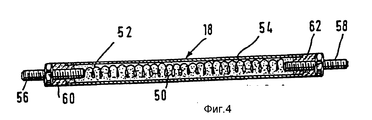
На фиг. 1 изображено схематическое продольное сечение первого варианта осуществления изобретения; на фиг. 2 разрез по линии II II на фиг. 1; на фиг. 3 схематическое изображение для пояснения изготовления корпуса-носителя варианта выполнения согласно фиг. 1 и 2; на фиг. 4 нагревательный элемент для варианта согласно фиг. 1-3, и на фиг. 5 схематическое изображение другого варианта выполнения с корпусом-носителем, изготовленным по способу звездной скрутки. In FIG. 1 is a schematic longitudinal section of a first embodiment of the invention; in FIG. 2 is a section along line II II of FIG. one; in FIG. 3 is a schematic diagram for explaining the manufacture of a carrier body of the embodiment of FIG. 1 and 2; in FIG. 4, the heating element for the embodiment according to FIG. 1-3, and in FIG. 5 is a schematic illustration of another embodiment with a carrier body manufactured by the stellar twisting method.
Катализаторы для отработавших газов, изображенные лишь схематически на фиг. 1 и 5 служат для превращения, соотв. каталитического дожигания отработавших газов, которые выделяет двигатель внутреннего сгорания легкового автомобиля. С помощью нагревательных элементов, используемых в катализаторах для отработавших газов, на фазе запуска двигателя внутреннего сгорания должен обеспечиваться повышенный КПД в процессе преобразования отработавших газов. Нагревательные элементы нагревают корпус-носитель вместе с его каталитическим покрытием, чем обеспечивается более быстрое достижение катализатором для отработавших газов своей рабочей температуры. Exhaust catalysts shown only schematically in FIG. 1 and 5 are used for transformation, respectively. catalytic afterburning of the exhaust gases that the internal combustion engine of a car emits. Using the heating elements used in the exhaust gas catalysts, an increased efficiency in the exhaust gas conversion process must be provided during the start-up phase of the internal combustion engine. The heating elements heat the carrier body together with its catalytic coating, which ensures that the exhaust gas catalyst reaches its operating temperature more quickly.
Изображенный на фиг. 1 в схематическом продольном разрезе катализатор (10) для отработавших газов имеет кожух (12) корпуса, изготовленный из высококачественной стали, включающий также в поперечном сечении цилиндрический корпус-носитель (13). Depicted in FIG. 1, in a schematic longitudinal section, the exhaust gas catalyst (10) has a housing casing (12) made of stainless steel, also including a cylindrical carrier body (13) in cross section.
Как следует из фиг. 2 корпус-носитель (13) состоит из свернутого в виде спирали гладкого металлического листа (14), причем витки расположены на определенном расстоянии друг от друга. Расстояние между витками гладкого металлического листа (14) устанавливается волнистым металлическим листом (16), расположенным между противолежащими витками. Как гладкий металлический лист (14), так и волнистый металлический лист (16) корпуса
Как видно из фиг. 1, присоединенные элементы нагревательных элементов (18, 20, 22, 24) находятся в области потока отработавших газов. Присоединительные элементы нагревательных элементов (18, 20, 22, 24), расположенные в области торцевой стороны (17, 19), могут соединяться друг с другом и соответственно подсоединяться к общему электропроводу (30, 32) (подробное изображение не представлено). При этом в дополнение к фиг. 1, может быть использована также электропроводность корпуса трубы (12). В этом случае провод (32) соединяется с корпусом трубы (12), который в свою очередь соединен с полюсом системы (34) электронагревания.As follows from FIG. 2, the carrier body (13) consists of a coiled smooth metal sheet (14), the turns being located at a certain distance from each other. The distance between the turns of the smooth metal sheet (14) is set by the corrugated metal sheet (16) located between the opposite turns. Both smooth metal sheet (14) and corrugated metal sheet (16) of the housing
As can be seen from FIG. 1, the attached elements of the heating elements (18, 20, 22, 24) are located in the exhaust gas flow region. The connecting elements of the heating elements (18, 20, 22, 24) located in the region of the end side (17, 19) can be connected to each other and, accordingly, connected to a common electric wire (30, 32) (a detailed image is not shown). Moreover, in addition to FIG. 1, the electrical conductivity of the pipe body (12) can also be used. In this case, the wire (32) is connected to the pipe body (12), which in turn is connected to the pole of the electric heating system (34).
Из фиг. 2 следует, что нагревательные элементы (18, 20, 22, 24) установлены в волнообразную форму волнистого металлического листа (16). Благодаря этому отпадает необходимость в дополнительных мерах по креплению нагревательных элементов (18, 20, 22, 24) для обеспечения из надежной фиксации в поперечном направлении корпуса-носителя (13). Так как диаметр нагревательных элементов (18, 20, 22, 24) соответствует волнообразной форме волнистого металлического листа (16), то обеспечивается особенно хороший поверхностный контакт между корпусом трубы (54) нагревательного элемента и металлическими листами (14 и 16) корпуса-носителя и тем самым обеспечивается хорошая теплопередача, так как в наличии имеется большая площадь теплопередачи. Это приводит, с одной стороны, к очень быстрому прогреву корпуса-носителя (13) и, с другой стороны, препятствует точечному перегреву, который может привести к разрушению корпуса-носителя (13). Равномерный нагрев корпуса-носителя (13) по всему его поперечному сечению обеспечивается с помощью большого количества нагревательных элементов (18, 20, 22, 24), распределенных по поперечному сечению). From FIG. 2 it follows that the heating elements (18, 20, 22, 24) are installed in a wave-like shape of a corrugated metal sheet (16). Due to this, there is no need for additional measures for fastening the heating elements (18, 20, 22, 24) to ensure reliable fixation in the transverse direction of the carrier body (13). Since the diameter of the heating elements (18, 20, 22, 24) corresponds to the wavy shape of the corrugated metal sheet (16), a particularly good surface contact is ensured between the pipe body (54) of the heating element and the metal sheets (14 and 16) of the carrier body and this ensures good heat transfer, since a large heat transfer area is available. This leads, on the one hand, to a very rapid heating of the carrier body (13) and, on the other hand, prevents point overheating, which can lead to destruction of the carrier body (13). Uniform heating of the carrier body (13) over its entire cross section is ensured by a large number of heating elements (18, 20, 22, 24) distributed over the cross section).
С помощью фиг. 3 поясняется изготовление катализатора для отработавших газов, представленного на фиг. 1 и 2. Корпус-носитель (13) изготавливается путем спиралеобразного скручивания ленточного гладкого металлического листа (14) и лентообразного волнистого металлического листа (16). Перед скручиванием корпуса-носителя (13) в волнообразную форму волнистого металлического листа (16) на определенном расстоянии друг от друга устанавливается необходимое количество нагревательных элементов (18, 20). При последующем скручивании корпуса-носителя (13) электрические нагревательные элементы (18, 20) прочно скрепляются со структурой корпуса-носителя (13). Благодаря такому способу изготовления отпадет необходимость в последующей установке нагревательных элементов в структуру корпуса-носителя (13). Кроме того, достигается особенно прочная связь и тем самым особенно прочный корпус-носитель (13). Представленные на фиг. 4 цилиндрические нагревательные элементы способствуют дальнейшему повышению прочности корпуса-носителя (13). Using FIG. 3 illustrates the manufacture of an exhaust gas catalyst of FIG. 1 and 2. The carrier body (13) is made by spiral twisting of a smooth tape metal sheet (14) and a ribbon-like corrugated metal sheet (16). Before twisting the carrier body (13) into a wavy shape of a corrugated metal sheet (16), a certain number of heating elements (18, 20) is set at a certain distance from each other. Upon subsequent twisting of the carrier body (13), the electric heating elements (18, 20) are firmly bonded to the structure of the carrier body (13). Thanks to this manufacturing method, there is no need for the subsequent installation of heating elements in the structure of the carrier body (13). In addition, a particularly strong bond is achieved, and thus a particularly strong carrier body (13). Presented in FIG. 4 cylindrical heating elements contribute to a further increase in the strength of the carrier body (13).
Так как электрические нагревательные элементы (18, 20, 22, 24) выполнены самоизолирующимися, то дальнейшие меры по изоляции на корпусе-носителе (13) не требуются. Таким образом отпадает необходимость в изоляционных слоях, которые в известных конструкциях ведут к снижению прочности корпуса-носителя (13). Since the electric heating elements (18, 20, 22, 24) are self-insulating, further insulation measures on the carrier body (13) are not required. Thus, there is no need for insulating layers, which in known constructions lead to a decrease in the strength of the carrier body (13).
В не представленном варианте выполнения вместо цилиндрических нагревательных элементов предусмотрены плоские или пленкообразные нагревательные элементы, которые наносятся на гладкую ленту (14). Так как подобные нагревательные элементы являются гибкими, то корпусу-носителю тем самым можно также придать спиралеобразную структуру. Однако также возможно, послойное исполнение корпуса-носителя. In an embodiment not shown, instead of cylindrical heating elements, flat or film-shaped heating elements are provided that are applied to a smooth tape (14). Since such heating elements are flexible, a helical structure can also be imparted to the carrier body. However, it is also possible layered execution of the carrier body.
Другой вариант осуществления изобретения схематично изображен на фиг. 5. Представленный здесь катализатор (80) для отработавших газов имеет цилиндрический кожух корпуса (82), включающий не изображенный корпус-носитель. Изготовленный из металлических листов корпус-носитель изготовлен по известному, в принципе, способу звездной скрутки (см. патент ФРГ 40 16 276). Этот корпус-носитель состоит также из гладких металлических листов, расположенных на определенном расстоянии друг от друга, причем в промежуточных пространствах расположены волнистые металлические листы. При изготовлении катализатора для отработавших газов перед скручиванием корпуса-носителя между слоями металлических листов устанавливается предварительно изготовленный электрический нагревательный элемент (84), форма которого изображена на фиг. 5. Электрические нагревательные элементы, которые пригодны для такого формообразования, имеются, в принципе, в продаже. Как следует из изображения, выполненный в виде гибкой трубки электрический нагревательный элемент имеет трехмерную меандрообразную форму. Электрические присоединительные элементы нагревательного элемента (84), расположенные на концевых участках, связаны с системой (86) электропитания транспортного средства. Another embodiment of the invention is shown schematically in FIG. 5. The exhaust gas catalyst (80) presented here has a cylindrical housing casing (82) including a carrier carrier not shown. A carrier body made of metal sheets is made by a known, in principle, stellar twisting method (see German Patent 40 16 276). This carrier body also consists of smooth metal sheets located at a certain distance from each other, with corrugated metal sheets located in the intermediate spaces. In the manufacture of an exhaust gas catalyst, before twisting the carrier body between the layers of metal sheets, a prefabricated electric heating element (84) is installed, the shape of which is shown in FIG. 5. Electric heating elements that are suitable for such shaping are, in principle, commercially available. As follows from the image, made in the form of a flexible tube, the electric heating element has a three-dimensional meander-like shape. The electrical connecting elements of the heating element (84) located at the end sections are connected to the vehicle power supply system (86).
Также в этом варианте осуществления изобретения благодаря нагревательному элементу (84), имеющему самоизоляцию, не требуются дополнительные меры по изоляции, которые могут уменьшить прочность корпуса-носителя. Напротив, благодаря меандрообразному электрическому нагревательному элементу (84) повышается прочность корпуса-носителя. Так как нагревательный элемент (84) равномерно распределен по всей поверхности поперечного сечения катализатора (80) для отработавших газов, обеспечивается быстрый и равномерный нагрев. Также не могут произойти локальные перегревы на корпусе-носителе. Also in this embodiment of the invention, due to the self-insulating heating element (84), no additional insulation measures are required that can reduce the strength of the carrier body. On the contrary, due to the meander-shaped electric heating element (84), the strength of the carrier body is increased. Since the heating element (84) is evenly distributed over the entire cross-sectional surface of the exhaust gas catalyst (80), fast and uniform heating is provided. Also, local overheating on the carrier body cannot occur.
С помощью описанных ранее вариантов выполнения возможно быстрое и равномерное нагревание предложенных в изобретении катализаторов для отработавших газов. Благодаря этому очень быстрым способом обеспечивается высокий КПД катализаторов для отработавших газов. Используемые самоизолирующиеся нагревательные элементы не требуют других дополнительных мер по изоляции, так что обеспечивается высокая прочность корпусов-носителей. Using the previously described embodiments, it is possible to quickly and uniformly heat the exhaust gas catalysts of the invention. Due to this, a very fast way provides a high efficiency of catalysts for exhaust gases. The self-insulating heating elements used do not require other additional insulation measures, so that high strength of the carrier bodies is ensured.
Claims (12)
Applications Claiming Priority (3)
| Application Number | Priority Date | Filing Date | Title |
|---|---|---|---|
| DEP4132439.0 | 1991-09-28 | ||
| DE4132439A DE4132439A1 (en) | 1991-09-28 | 1991-09-28 | EXHAUST CATALYST |
| PCT/EP1992/002116 WO1993007364A1 (en) | 1991-09-28 | 1992-09-15 | Exhaust gas catalytic converter |
Publications (2)
| Publication Number | Publication Date |
|---|---|
| RU94017662A RU94017662A (en) | 1996-04-27 |
| RU2100624C1 true RU2100624C1 (en) | 1997-12-27 |
Family
ID=6441756
Family Applications (1)
| Application Number | Title | Priority Date | Filing Date |
|---|---|---|---|
| RU9494017662A RU2100624C1 (en) | 1991-09-28 | 1992-09-15 | Catalyzer for exhaust gases |
Country Status (12)
| Country | Link |
|---|---|
| US (1) | US5562885A (en) |
| EP (1) | EP0605479B1 (en) |
| JP (1) | JP2528805B2 (en) |
| KR (1) | KR100225194B1 (en) |
| BR (1) | BR9206558A (en) |
| CZ (1) | CZ58094A3 (en) |
| DE (2) | DE4132439A1 (en) |
| ES (1) | ES2072769T3 (en) |
| MX (1) | MX9205465A (en) |
| RU (1) | RU2100624C1 (en) |
| TW (1) | TW209268B (en) |
| WO (1) | WO1993007364A1 (en) |
Families Citing this family (37)
| Publication number | Priority date | Publication date | Assignee | Title |
|---|---|---|---|---|
| DE19512097A1 (en) * | 1995-04-03 | 1996-10-10 | Roth Technik Gmbh | Electrically heated motor exhaust gas catalyst in narrow structure |
| FR2741675B1 (en) | 1995-11-23 | 1998-01-02 | Inst Francais Du Petrole | METHOD AND DEVICE FOR AIDING THE COLD STARTING OF MOTOR VEHICLES |
| US6328936B1 (en) * | 1999-10-05 | 2001-12-11 | Precision Combustion, Inc. | Catalytic reactor for promoting a chemical reaction on a fluid passing therethrough |
| DE10056279A1 (en) * | 2000-11-14 | 2002-05-29 | Emitec Emissionstechnologie | Radially flowable and segmented honeycomb body |
| MXPA03004997A (en) * | 2000-12-05 | 2003-09-05 | Texaco Development Corp | Apparatus and method for heating catalyst for start-up of a compact fuel processor. |
| KR20030018098A (en) * | 2001-08-27 | 2003-03-06 | 현대자동차주식회사 | metallic substrate of catalytic converter |
| US20090025327A1 (en) * | 2007-03-26 | 2009-01-29 | Albracht Gregory P | Furring Strip Alignment System |
| US8388741B2 (en) | 2007-08-14 | 2013-03-05 | GM Global Technology Operations LLC | Electrically heated particulate filter with reduced stress |
| US8057581B2 (en) * | 2007-08-31 | 2011-11-15 | GM Global Technology Operations LLC | Zoned electrical heater arranged in spaced relationship from particulate filter |
| US7981198B2 (en) * | 2007-09-14 | 2011-07-19 | GM Global Technology Operations LLC | Overlap zoned electrically heated particulate filter |
| EP2190569B1 (en) * | 2007-09-18 | 2015-07-22 | Amo Co., Ltd. | Monolith, catalyst convertor for purifying exhaust gas using the same and method for manufacturing the catalyst |
| DE102008011262A1 (en) * | 2008-02-27 | 2009-09-03 | Emitec Gesellschaft Für Emissionstechnologie Mbh | Honeycomb body with connection-free area |
| DE102008011263A1 (en) * | 2008-02-27 | 2009-09-03 | Emitec Gesellschaft Für Emissionstechnologie Mbh | Honeycomb body with flexibility zones |
| DE102008025761A1 (en) * | 2008-05-29 | 2009-12-10 | Oberland Mangold Gmbh | Metallic support for catalysts or particle separators and use of this support |
| EP3195929B1 (en) * | 2009-02-27 | 2019-09-25 | Inventys Thermal Technologies Inc. | Parallel passage fluid contactor structure |
| CN103180028B (en) | 2010-08-27 | 2016-07-06 | 英温提斯热力技术有限公司 | The method using thermal conductive contact device structure adsorption seperation of gas |
| US10315159B2 (en) | 2010-08-27 | 2019-06-11 | Inventys Thermal Technoogies Inc. | Method of adsorptive gas separation using thermally conductive contactor structure |
| CA2964550C (en) | 2011-07-02 | 2019-07-23 | Inventys Thermal Technologies Inc. | System and method for integrated adsorptive gas separation of combustion gases |
| DE102012008183B4 (en) * | 2011-09-06 | 2013-07-18 | Joachim Benz | heat exchanger kit |
| DE102012217875A1 (en) * | 2012-09-28 | 2014-04-03 | Behr Gmbh & Co. Kg | Heat exchanger |
| US11060433B2 (en) * | 2013-09-18 | 2021-07-13 | Advanced Technology Emission Solutions Inc. | Retention of wires in an induction heated gaseous emissions treatment unit |
| DE102014015508B4 (en) | 2014-10-21 | 2018-09-27 | Joachim Benz | heat exchanger kit |
| KR102320147B1 (en) * | 2015-02-24 | 2021-11-02 | 현대두산인프라코어 주식회사 | Mixing device for reducing agent and selective catalyst reduction system having the same |
| DE102015212705A1 (en) * | 2015-07-07 | 2017-01-12 | Continental Automotive Gmbh | Layer package contacting for electrically heated honeycomb bodies |
| DE102015111689C5 (en) * | 2015-07-17 | 2022-09-01 | Türk & Hillinger GmbH | Electrically heatable catalyst and process for its production |
| RU2624706C2 (en) * | 2016-07-06 | 2017-07-05 | Баир Сыдыпович Бальжинимаев | Method and installation for purifying waste gases |
| DE102016214495A1 (en) | 2016-08-04 | 2018-02-08 | Continental Automotive Gmbh | Electrically heatable honeycomb body for exhaust gas treatment with a plurality of heating elements |
| CA3042226C (en) | 2016-10-31 | 2024-02-13 | Watlow Electric Manufacturing Company | High power density insulated exhaust heating system |
| DE102016223578A1 (en) * | 2016-11-28 | 2018-05-30 | Continental Automotive Gmbh | Device for evaporating a fluid |
| GB2559565B (en) * | 2017-02-08 | 2020-10-07 | Jaguar Land Rover Ltd | Catalytic converter system with internal heating device |
| JP2018178768A (en) * | 2017-04-05 | 2018-11-15 | 日本特殊陶業株式会社 | Catalyst device of internal combustion engine |
| DE102018200464A1 (en) * | 2018-01-12 | 2019-07-18 | Continental Automotive Gmbh | Apparatus and method for heating a device for exhaust aftertreatment |
| DE102018200463A1 (en) * | 2018-01-12 | 2019-07-18 | Continental Automotive Gmbh | heating element |
| EP3772575B1 (en) * | 2019-08-06 | 2022-03-16 | HIDRIA d.o.o. | Exhaust gas purification device and method for manufacturing the same |
| DE102020121414A1 (en) * | 2020-08-14 | 2022-02-17 | Purem GmbH | exhaust gas heating arrangement |
| US20220082042A1 (en) * | 2020-09-17 | 2022-03-17 | Advanced Technology Emission Solutions Inc. | Apparatus and method for gaseous emissions treatment with resistive heating |
| DE102022125694A1 (en) | 2022-10-05 | 2024-04-11 | Tenneco Gmbh | Heating element |
Family Cites Families (22)
| Publication number | Priority date | Publication date | Assignee | Title |
|---|---|---|---|---|
| DE563757C (en) * | 1929-08-12 | |||
| US3768982A (en) * | 1971-06-22 | 1973-10-30 | Ford Motor Co | Catalytic converter with electrically preheated catalyst |
| US3770389A (en) * | 1971-11-11 | 1973-11-06 | Ford Motor Co | Catalytic converter with electrically resistive catalyst support |
| US3889464A (en) * | 1973-12-20 | 1975-06-17 | Conrad O Gardner | Exhaust emission control systems and devices |
| DE2825980A1 (en) * | 1978-06-14 | 1980-01-03 | Eichenauer Fa Fritz | ELECTRIC PIPE RADIATOR AND METHOD FOR THE PRODUCTION THEREOF |
| DE2951316A1 (en) * | 1979-12-20 | 1981-07-02 | Degussa Ag, 6000 Frankfurt | CATALYTIC FILTER FOR DIESEL EXHAUST CLEANING |
| EP0079386B1 (en) * | 1981-05-19 | 1986-08-27 | Matsushita Electric Industrial Co., Ltd. | A shielded heating element |
| US4544388A (en) * | 1983-12-27 | 1985-10-01 | Ford Motor Company | Apparatus for periodically oxidizing particulates collected from exhaust gases |
| ATE63611T1 (en) * | 1986-02-19 | 1991-06-15 | Boehler Gmbh | EMISSION CONTROL DEVICE. |
| DE8621551U1 (en) * | 1986-08-11 | 1986-10-09 | Siemens AG, 1000 Berlin und 8000 München | Electric heating device for catalytic afterburning devices in Otto engines |
| DE8700787U1 (en) * | 1987-01-17 | 1987-10-22 | Guertler, Johann, 6074 Roedermark, De | |
| DE8816514U1 (en) * | 1988-04-25 | 1989-10-26 | Emitec Emissionstechnologie | |
| US4976929A (en) * | 1988-05-20 | 1990-12-11 | W. R. Grace & Co.-Conn. | Electrically heated catalytic converter |
| US4942020A (en) * | 1988-06-27 | 1990-07-17 | W.R. Grace & Co.-Conn. | Converter for removing pollutants from a gas stream |
| DE3903879A1 (en) * | 1989-02-10 | 1990-08-16 | Messer Griesheim Gmbh | Heater for a catalytic converter comprising a metallic monolith and an electrically conducting housing |
| US5294411A (en) * | 1989-04-17 | 1994-03-15 | Emitec Gesellschaft Fuer Emissionstechnologie Mbh | Honeycomb body with heatable catalytic active coating |
| DE8905073U1 (en) * | 1989-04-21 | 1990-08-30 | Emitec Emissionstechnologie | |
| US4928485A (en) * | 1989-06-06 | 1990-05-29 | W. R. Grace & Co.,-Conn. | Metallic core member for catalytic converter and catalytic converter containing same |
| DE3929521A1 (en) * | 1989-09-06 | 1991-03-14 | Wilhelm F Prof Dr Maier | Directly heated air cleaning catalyst - comprising oxidn. catalyst-coated metal wire or strip |
| US5118475A (en) * | 1989-09-12 | 1992-06-02 | W. R. Grace & Co.-Conn. | Core element and core for electrically heatable catalytic converter |
| DE4016276C1 (en) * | 1990-05-21 | 1991-06-20 | Behr Gmbh & Co | |
| JPH04179818A (en) * | 1990-11-14 | 1992-06-26 | Nippon Soken Inc | Exhaust gas fine particles purifing device |
-
1991
- 1991-09-28 DE DE4132439A patent/DE4132439A1/en not_active Withdrawn
-
1992
- 1992-09-15 DE DE59202266T patent/DE59202266D1/en not_active Expired - Fee Related
- 1992-09-15 JP JP5506571A patent/JP2528805B2/en not_active Expired - Fee Related
- 1992-09-15 EP EP92919163A patent/EP0605479B1/en not_active Expired - Lifetime
- 1992-09-15 WO PCT/EP1992/002116 patent/WO1993007364A1/en not_active Application Discontinuation
- 1992-09-15 BR BR9206558A patent/BR9206558A/en not_active IP Right Cessation
- 1992-09-15 ES ES92919163T patent/ES2072769T3/en not_active Expired - Lifetime
- 1992-09-15 KR KR1019940700992A patent/KR100225194B1/en not_active IP Right Cessation
- 1992-09-15 CZ CS94580A patent/CZ58094A3/en unknown
- 1992-09-15 RU RU9494017662A patent/RU2100624C1/en not_active IP Right Cessation
- 1992-09-25 MX MX9205465A patent/MX9205465A/en active IP Right Grant
- 1992-09-25 TW TW081107605A patent/TW209268B/zh active
-
1994
- 1994-03-24 US US08/217,583 patent/US5562885A/en not_active Expired - Lifetime
Non-Patent Citations (1)
| Title |
|---|
| US, патент, 3889464, кл. A 43 B 3/12, 1975. * |
Also Published As
| Publication number | Publication date |
|---|---|
| JP2528805B2 (en) | 1996-08-28 |
| EP0605479A1 (en) | 1994-07-13 |
| RU94017662A (en) | 1996-04-27 |
| DE59202266D1 (en) | 1995-06-22 |
| WO1993007364A1 (en) | 1993-04-15 |
| JPH07500052A (en) | 1995-01-05 |
| US5562885A (en) | 1996-10-08 |
| BR9206558A (en) | 1995-11-21 |
| DE4132439A1 (en) | 1993-04-01 |
| CZ58094A3 (en) | 1994-08-17 |
| KR100225194B1 (en) | 1999-10-15 |
| TW209268B (en) | 1993-07-11 |
| ES2072769T3 (en) | 1995-07-16 |
| EP0605479B1 (en) | 1995-05-17 |
| KR940702582A (en) | 1994-08-20 |
| MX9205465A (en) | 1993-05-01 |
Similar Documents
| Publication | Publication Date | Title |
|---|---|---|
| RU2100624C1 (en) | Catalyzer for exhaust gases | |
| US6513324B2 (en) | Device with heating element for exhaust gas cleaning | |
| JP2787827B2 (en) | Conductive honeycomb body | |
| US5070694A (en) | Structure for electrically heatable catalytic core | |
| US5174968A (en) | Structure for electrically heatable catalytic core | |
| CN111472869B (en) | Exhaust gas heating element | |
| JP7254887B2 (en) | Exhaust gas heating unit | |
| US5585073A (en) | Electrically heated catalytic converter | |
| JPH08103664A (en) | Honeycomb body and catalytic converter having catalyst carrier consisting of the honeycomb body | |
| US5240682A (en) | Reinforced corrugated thin metal foil strip useful in a catalytic converter core, a catalytic converter core containing said strip and an electrically heatable catalytic converter containing said core | |
| JPH04136412A (en) | Heating device of honeycomb catalytic converter | |
| RU95119392A (en) | CATALYTIC CONVERTER WITH ELECTRIC HEATING | |
| KR100234225B1 (en) | Honeycomb construction with inner structure held in a frame | |
| JPH0540251Y2 (en) | ||
| US11781459B2 (en) | Heating unit for an exhaust-gas system of an internal combustion engine | |
| US11572817B2 (en) | Exhaust gas heating arrangement | |
| CA2049634A1 (en) | Electrically heated catalytic converter | |
| CN114592949A (en) | Exhaust gas treatment device for arrangement in an exhaust system of a motor vehicle | |
| JPH08108076A (en) | Catalytic converter | |
| JP3312933B2 (en) | Electric heating type honeycomb body | |
| US11328865B2 (en) | Method of winding | |
| JP3208020B2 (en) | Metal carrier for electrically heated catalyst device | |
| JP3340860B2 (en) | Metal carrier for electric heating type catalytic device | |
| JP3269653B2 (en) | Electric heating type honeycomb body | |
| JP2023036037A (en) | Exhaust gas device |
Legal Events
| Date | Code | Title | Description |
|---|---|---|---|
| MM4A | The patent is invalid due to non-payment of fees |
Effective date: 20090916 |