RU2080262C1 - Method and apparatus for thermal molding of hollow objects with thermoplastic material sheet as their basis - Google Patents
Method and apparatus for thermal molding of hollow objects with thermoplastic material sheet as their basis Download PDFInfo
- Publication number
- RU2080262C1 RU2080262C1 RU9393004492A RU93004492A RU2080262C1 RU 2080262 C1 RU2080262 C1 RU 2080262C1 RU 9393004492 A RU9393004492 A RU 9393004492A RU 93004492 A RU93004492 A RU 93004492A RU 2080262 C1 RU2080262 C1 RU 2080262C1
- Authority
- RU
- Russia
- Prior art keywords
- products
- product
- matrix
- conveyor
- molding
- Prior art date
Links
Images


Classifications
-
- B—PERFORMING OPERATIONS; TRANSPORTING
- B29—WORKING OF PLASTICS; WORKING OF SUBSTANCES IN A PLASTIC STATE IN GENERAL
- B29C—SHAPING OR JOINING OF PLASTICS; SHAPING OF MATERIAL IN A PLASTIC STATE, NOT OTHERWISE PROVIDED FOR; AFTER-TREATMENT OF THE SHAPED PRODUCTS, e.g. REPAIRING
- B29C51/00—Shaping by thermoforming, i.e. shaping sheets or sheet like preforms after heating, e.g. shaping sheets in matched moulds or by deep-drawing; Apparatus therefor
- B29C51/26—Component parts, details or accessories; Auxiliary operations
- B29C51/44—Removing or ejecting moulded articles
-
- B—PERFORMING OPERATIONS; TRANSPORTING
- B29—WORKING OF PLASTICS; WORKING OF SUBSTANCES IN A PLASTIC STATE IN GENERAL
- B29C—SHAPING OR JOINING OF PLASTICS; SHAPING OF MATERIAL IN A PLASTIC STATE, NOT OTHERWISE PROVIDED FOR; AFTER-TREATMENT OF THE SHAPED PRODUCTS, e.g. REPAIRING
- B29C51/00—Shaping by thermoforming, i.e. shaping sheets or sheet like preforms after heating, e.g. shaping sheets in matched moulds or by deep-drawing; Apparatus therefor
-
- B—PERFORMING OPERATIONS; TRANSPORTING
- B29—WORKING OF PLASTICS; WORKING OF SUBSTANCES IN A PLASTIC STATE IN GENERAL
- B29C—SHAPING OR JOINING OF PLASTICS; SHAPING OF MATERIAL IN A PLASTIC STATE, NOT OTHERWISE PROVIDED FOR; AFTER-TREATMENT OF THE SHAPED PRODUCTS, e.g. REPAIRING
- B29C31/00—Handling, e.g. feeding of the material to be shaped, storage of plastics material before moulding; Automation, i.e. automated handling lines in plastics processing plants, e.g. using manipulators or robots
-
- B—PERFORMING OPERATIONS; TRANSPORTING
- B29—WORKING OF PLASTICS; WORKING OF SUBSTANCES IN A PLASTIC STATE IN GENERAL
- B29C—SHAPING OR JOINING OF PLASTICS; SHAPING OF MATERIAL IN A PLASTIC STATE, NOT OTHERWISE PROVIDED FOR; AFTER-TREATMENT OF THE SHAPED PRODUCTS, e.g. REPAIRING
- B29C37/00—Component parts, details, accessories or auxiliary operations, not covered by group B29C33/00 or B29C35/00
- B29C37/0003—Discharging moulded articles from the mould
- B29C37/0007—Discharging moulded articles from the mould using means operable from outside the mould for moving between mould parts, e.g. robots
-
- B—PERFORMING OPERATIONS; TRANSPORTING
- B29—WORKING OF PLASTICS; WORKING OF SUBSTANCES IN A PLASTIC STATE IN GENERAL
- B29C—SHAPING OR JOINING OF PLASTICS; SHAPING OF MATERIAL IN A PLASTIC STATE, NOT OTHERWISE PROVIDED FOR; AFTER-TREATMENT OF THE SHAPED PRODUCTS, e.g. REPAIRING
- B29C51/00—Shaping by thermoforming, i.e. shaping sheets or sheet like preforms after heating, e.g. shaping sheets in matched moulds or by deep-drawing; Apparatus therefor
- B29C51/18—Thermoforming apparatus
- B29C51/20—Thermoforming apparatus having movable moulds or mould parts
-
- B—PERFORMING OPERATIONS; TRANSPORTING
- B29—WORKING OF PLASTICS; WORKING OF SUBSTANCES IN A PLASTIC STATE IN GENERAL
- B29C—SHAPING OR JOINING OF PLASTICS; SHAPING OF MATERIAL IN A PLASTIC STATE, NOT OTHERWISE PROVIDED FOR; AFTER-TREATMENT OF THE SHAPED PRODUCTS, e.g. REPAIRING
- B29C51/00—Shaping by thermoforming, i.e. shaping sheets or sheet like preforms after heating, e.g. shaping sheets in matched moulds or by deep-drawing; Apparatus therefor
- B29C51/26—Component parts, details or accessories; Auxiliary operations
-
- B—PERFORMING OPERATIONS; TRANSPORTING
- B29—WORKING OF PLASTICS; WORKING OF SUBSTANCES IN A PLASTIC STATE IN GENERAL
- B29C—SHAPING OR JOINING OF PLASTICS; SHAPING OF MATERIAL IN A PLASTIC STATE, NOT OTHERWISE PROVIDED FOR; AFTER-TREATMENT OF THE SHAPED PRODUCTS, e.g. REPAIRING
- B29C2793/00—Shaping techniques involving a cutting or machining operation
- B29C2793/0045—Perforating
-
- B—PERFORMING OPERATIONS; TRANSPORTING
- B29—WORKING OF PLASTICS; WORKING OF SUBSTANCES IN A PLASTIC STATE IN GENERAL
- B29C—SHAPING OR JOINING OF PLASTICS; SHAPING OF MATERIAL IN A PLASTIC STATE, NOT OTHERWISE PROVIDED FOR; AFTER-TREATMENT OF THE SHAPED PRODUCTS, e.g. REPAIRING
- B29C51/00—Shaping by thermoforming, i.e. shaping sheets or sheet like preforms after heating, e.g. shaping sheets in matched moulds or by deep-drawing; Apparatus therefor
- B29C51/04—Combined thermoforming and prestretching, e.g. biaxial stretching
-
- B—PERFORMING OPERATIONS; TRANSPORTING
- B29—WORKING OF PLASTICS; WORKING OF SUBSTANCES IN A PLASTIC STATE IN GENERAL
- B29C—SHAPING OR JOINING OF PLASTICS; SHAPING OF MATERIAL IN A PLASTIC STATE, NOT OTHERWISE PROVIDED FOR; AFTER-TREATMENT OF THE SHAPED PRODUCTS, e.g. REPAIRING
- B29C51/00—Shaping by thermoforming, i.e. shaping sheets or sheet like preforms after heating, e.g. shaping sheets in matched moulds or by deep-drawing; Apparatus therefor
- B29C51/08—Deep drawing or matched-mould forming, i.e. using mechanical means only
- B29C51/082—Deep drawing or matched-mould forming, i.e. using mechanical means only by shaping between complementary mould parts
-
- B—PERFORMING OPERATIONS; TRANSPORTING
- B29—WORKING OF PLASTICS; WORKING OF SUBSTANCES IN A PLASTIC STATE IN GENERAL
- B29C—SHAPING OR JOINING OF PLASTICS; SHAPING OF MATERIAL IN A PLASTIC STATE, NOT OTHERWISE PROVIDED FOR; AFTER-TREATMENT OF THE SHAPED PRODUCTS, e.g. REPAIRING
- B29C51/00—Shaping by thermoforming, i.e. shaping sheets or sheet like preforms after heating, e.g. shaping sheets in matched moulds or by deep-drawing; Apparatus therefor
- B29C51/16—Lining or labelling
-
- B—PERFORMING OPERATIONS; TRANSPORTING
- B29—WORKING OF PLASTICS; WORKING OF SUBSTANCES IN A PLASTIC STATE IN GENERAL
- B29C—SHAPING OR JOINING OF PLASTICS; SHAPING OF MATERIAL IN A PLASTIC STATE, NOT OTHERWISE PROVIDED FOR; AFTER-TREATMENT OF THE SHAPED PRODUCTS, e.g. REPAIRING
- B29C51/00—Shaping by thermoforming, i.e. shaping sheets or sheet like preforms after heating, e.g. shaping sheets in matched moulds or by deep-drawing; Apparatus therefor
- B29C51/26—Component parts, details or accessories; Auxiliary operations
- B29C51/30—Moulds
- B29C51/32—Moulds having cutting means
-
- B—PERFORMING OPERATIONS; TRANSPORTING
- B29—WORKING OF PLASTICS; WORKING OF SUBSTANCES IN A PLASTIC STATE IN GENERAL
- B29L—INDEXING SCHEME ASSOCIATED WITH SUBCLASS B29C, RELATING TO PARTICULAR ARTICLES
- B29L2031/00—Other particular articles
- B29L2031/712—Containers; Packaging elements or accessories, Packages
- B29L2031/7132—Bowls, Cups, Glasses
-
- Y—GENERAL TAGGING OF NEW TECHNOLOGICAL DEVELOPMENTS; GENERAL TAGGING OF CROSS-SECTIONAL TECHNOLOGIES SPANNING OVER SEVERAL SECTIONS OF THE IPC; TECHNICAL SUBJECTS COVERED BY FORMER USPC CROSS-REFERENCE ART COLLECTIONS [XRACs] AND DIGESTS
- Y10—TECHNICAL SUBJECTS COVERED BY FORMER USPC
- Y10S—TECHNICAL SUBJECTS COVERED BY FORMER USPC CROSS-REFERENCE ART COLLECTIONS [XRACs] AND DIGESTS
- Y10S425/00—Plastic article or earthenware shaping or treating: apparatus
- Y10S425/20—Molding plants
- Y10S425/201—Diverse stations
Abstract
Description
Изобретение относится к переработке пластмасс, а именно к способу и устройству для термического формования полых чашеобразных предметов, таких как мензурки, бокалы, баки, из листа термопласта. The invention relates to the processing of plastics, and in particular to a method and apparatus for thermally molding hollow bowl-shaped objects, such as beakers, glasses, tanks, from a sheet of thermoplastic.
Известен способ термического формования полых изделий из листового материала, при котором осуществляют подачу материала из рулона, нагрев его, придание материалу формы формообразующей поверхности матрицы, охлаждение изделия и вырезание его, причем операции формования и отрезания изделия от листа исходного материала производят в одной рабочей позиции (патент Италии N 1175178, кл. B 29 C 33/44, 51/44, 1987). A known method of thermal molding of hollow products from sheet material, in which the material is supplied from the roll, is heated, the shape of the forming surface of the matrix is formed, the product is cooled and cut, and the operations of forming and cutting the product from the source material sheet are performed in one working position ( Italian Patent No. 1175178, CL B 29
Для осуществления указанного способа служит устройство для термического формования полых изделий, содержащее нагреватели, пресс, включающий верхний пуансон и нижнюю матрицу, состоящие из одной или нескольких частей, средства для охлаждения изделия, средство для его вырезания и средства для удаления изделия и укладки их в стопу (патент Италии N 1175178, кл. B 29 C 33/44, 51/44, 1987). To implement this method, a device for thermally molding hollow articles containing heaters, a press including an upper punch and a lower matrix, consisting of one or several parts, means for cooling the product, means for cutting it and means for removing the product and stacking them in the foot (Italian patent N 1175178, CL B 29
В известном способе и устройстве для удаления изделий из зоны формования и укладки их в стопки может быть использована система с нагнетанием воздуха, включающая сопла, образующие струи воздуха, которые приподнимают изделия, принуждая их опрокидываться в сборные каналы. Изделия при этом, продолжая путь вдоль сборного канала, укладываются друг на друга, образуя стопу. Однако эта система может быть использована только в случае, если изделия в матрице расположены в один ряд. Если изделия в матрице расположены в несколько рядов, необходимо использовать укладчик, работающий синхронно с термоформовочной машиной. Это влечет дополнительные расходы, более сложную работу и высокий процент бракованных изделий. In the known method and device for removing products from the forming zone and stacking them in stacks, an air injection system can be used, including nozzles forming air jets that lift the products, forcing them to tip over into collecting channels. At the same time, the products, continuing the path along the collecting channel, are stacked on each other, forming a foot. However, this system can only be used if the products in the matrix are arranged in one row. If the products in the matrix are arranged in several rows, it is necessary to use a stacker that works synchronously with the thermoforming machine. This entails additional costs, more complex work and a high percentage of defective products.
Для удаления изделий из зоны формования и укладки может быть использована также система, включающая всасывающую пластину, которая вставляется между верхней кромкой изделия и выдуваемыми обрезками исходного материала в таком положении, что изделия могут присасываться, когда матрица закончила свое движение вниз. Затем всасывающая пластина перемещается в сторону в зону, смежную с термоформовочной машиной, где изделия подбираются всасывающими устройствами. Однако при использовании указанной системы пресс должен открываться на очень большое расстояние, поэтому производительность машины будет тем ниже, чем выше извлекаемые изделия. Сохранение пресса открытым в течение времени, необходимого для входа и выхода всасывающей пластины, увеличивает мертвое время в цикле термического формования. На производительность машины влияет также время, в течение которого изделие остается в прессе при его охлаждении, размер и форма всасывающей пластины. A system may also be used to remove products from the forming and stacking zone, including a suction plate that is inserted between the upper edge of the product and the blown scraps of the starting material in such a position that the products can be sucked in when the matrix has finished its downward movement. Then the suction plate is moved to the side in the area adjacent to the thermoforming machine, where the products are selected by suction devices. However, when using this system, the press must open over a very large distance, so the productivity of the machine will be the lower, the higher the recoverable products. Keeping the press open for the time required to enter and exit the suction plate increases the dead time in the thermal molding cycle. The productivity of the machine is also affected by the time during which the product remains in the press while it is cooling, the size and shape of the suction plate.
На известном устройстве невозможно также осуществить ни одной дополнительной операции на изделиях между операциями удаления из пресса и укладкой в стопы. On the known device it is also impossible to carry out any additional operations on the products between the operations of removal from the press and stacking in the feet.
Наиболее близким по технической сущности к изобретению является способ термического формования полых изделий, имеющих основание из листа термопластичного материала, в котором за один разовый заданный операционный цикл выполняют операции изготовления штамованного изделия путем горячего формования и вырезания изделия между одной половиной подвижной двойной матрицы, которая расположена в зоне формования напротив пуансона, перемещения половины матрицы с находящимися в ней изделием или изделиями в направлении соответствующей разгрузочной зоны, расположенной по обе стороны от зоны формования, попеременно то в одну, то в другую сторону от зоны формования и извлечения изделия или изделий из половины матрицы, находящейся в соответствующей разгрузочной зоне (патент Италии N 1053243, кл. B 29 C 33/44, 51/44, 1981). Closest to the technical essence of the invention is a method for thermally molding hollow articles having a base from a sheet of thermoplastic material, in which, for a single predetermined operating cycle, operations are carried out for manufacturing a fabricated article by hot molding and cutting the article between one half of the movable double matrix, which is located in the molding zone opposite the punch, moving half of the matrix with the product or products in it in the direction of the corresponding discharge part of the zone located on both sides of the molding zone, alternately either one or the other side of the molding zone and removing the product or products from half of the matrix located in the corresponding discharge zone (Italian patent N 1053243, CL B 29
Для осуществления известного способа служит устройство для термического формования полых изделий, имеющих основание из листа термопластичного материала, содержащее смонтированные на прессе пуансон и матрицу, имеющую две половины, которая установлена с возможностью поочередного соединения одной из половин матрицы с пуансоном при горизонтальном перемещении матрицы относительно пуансона, при этом при смыкании с пуансоном вторая половина матрицы переносит сформованное изделие в легко доступную разгрузочную зону, шаговое средство для подачи листа термопластичного материала между пуансоном и матрицей и режущее средство, которое может приводиться в действие в конце каждого движения закрытия пресса (патент Италии N 1053243, кл. B 29 C 33/44, 51/44, 1981). To implement the known method, there is a device for thermoforming hollow articles having a base made of a sheet of thermoplastic material, comprising a punch mounted on a press and a matrix having two halves, which is installed with the possibility of alternately connecting one of the matrix halves with a punch during horizontal movement of the matrix relative to the punch, at the same time, when closing with a punch, the second half of the matrix transfers the molded product to an easily accessible unloading zone, a step means for odachi sheet of thermoplastic material between the punch and the die and a cutting means which can be actuated at the end of each closing movement of the press (Italian patent N 1053243, cl. B 29
В известном способе и устройстве расстояние, на которое открывается пресс, не зависит от глубины или высоты формуемых изделий и поэтому может быть минимальным с большим сокращением пассивного времени в цикле, при этом пресс остается открытым только в течение времени, необходимом для продвижения листового материала и выполнения попеременного бокового движения матриц. Эти операции происходят одновременно без останова пресса для извлечения сформованных изделий. Время, в течение которого изделия остаются в полости, находясь в контакте с матрицей, длительнее, чем цикл термического формования, потому что изделия остаются в контакте с матрицей с момента вырезания до следующей операции формования в другой матрицей. Укладка изделий в стопы происходит в укладчике, при этом элементы основания удаляют изделия и укладывают их в стопы, попеременно толкая изделия, сформованные в одной форме, в левое устройство накопления или укладки. Поэтому может случиться, что изделия, которые имеют углубленные угловые опорные участки, предусмотренные для предотвращения слипания изделий друг с другом во время укладки, строго ориентированы в вертикальном направлении и соосны, так как все они поступили из одной и той же формы. В этом случае имеет место точное наложение друг на друга изделий, так что пространственный эффект опор или углублений нейтрализуется и как результат, изделия прочно связываются вместе, затрудняя их разъединение. Другая причина необратимого прилипания друг к другу изделий заключается в неточном формовании разъединяющих опор или углублений, т.е. термопластичный материал является нестабильным по размерам при формовании и они образуются с довольно широкими размерными допусками. Поэтому углы, образованные в месте соединения опоры и основания каждого изделия, могут быть различными в зависимости от природы термопластичного материала, формы и высоты формуемых изделий, что неприемлемо для правильной укладки изделий. Изделия, которые не вынимаются из стопы или вынимаются с трудом, требуют ручного вмешательства, снижают производительность и почти всегда приводят к увеличению брака. Кроме того, в машинах с двойной матрицей укладка изделий в стопы также происходит без возможности осуществления дополнительных операций со сформованными изделиями, так как они укладываются в стопы сразу после формования. In the known method and device, the distance that the press opens does not depend on the depth or height of the molded products and therefore can be minimal with a large reduction in passive time in the cycle, while the press remains open only for the time necessary to advance the sheet material and perform alternating lateral movement of the matrices. These operations take place simultaneously without stopping the press to extract molded products. The time during which the products remain in the cavity in contact with the matrix is longer than the thermoforming cycle, because the products remain in contact with the matrix from the moment of cutting to the next molding operation in another matrix. The products are stacked in the stacker, while the base elements remove the products and stack them in the stacks, alternately pushing the products formed in the same shape into the left storage or stacking device. Therefore, it may happen that products that have recessed angular support sections provided to prevent the products from sticking together during stacking are strictly oriented in the vertical direction and are coaxial, since they all came from the same shape. In this case, there is an exact superposition of the products on each other, so that the spatial effect of the supports or recesses is neutralized and, as a result, the products are firmly bonded together, making them difficult to separate. Another reason for the irreversible adhesion of products to each other is inaccurate molding of the disconnecting supports or recesses, i.e. thermoplastic material is unstable in size during molding and they are formed with fairly wide dimensional tolerances. Therefore, the angles formed at the junction of the support and the base of each product can be different depending on the nature of the thermoplastic material, the shape and height of the molded products, which is unacceptable for proper installation of the products. Products that cannot be removed from the foot or are removed with difficulty require manual intervention, reduce productivity and almost always lead to an increase in marriage. In addition, in machines with a double matrix, stacking of products in feet also occurs without the possibility of additional operations with molded products, since they are stacked in feet immediately after molding.
Техническим результатом изобретения является исключение прилипания сформованных изделий при укладке их с стопу, обеспечение возможности выполнения дополнительных операций над изделиями в течение каждого цикла формования, снижение времени ожидания пресса в открытом состоянии и уменьшение высоты пресса. The technical result of the invention is to prevent sticking of molded products when stacking them from the stack, providing the possibility of performing additional operations on the products during each molding cycle, reducing the waiting time of the press in the open state and reducing the height of the press.
Для достижения технического результата в способе термического формования полых изделий, имеющих основание из листа термопластичного материала, в котором за один разовый заданный операционный цикл выполняют операции изготовления штампованного изделия путем горячего формования и вырезания изделия или изделий между одной половиной подвижной двойной матрицы, которая расположена в зоне формования напротив пуансона, перемещения половины матрицы с находящимся в ней изделием или изделиями в направлении соответствующей разгрузочной зоны, расположенной по обе стороны от зоны формования, попеременно то в одну, то в другую сторону от зоны формования и извлечения изделия или изделий из половины матрицы, находящейся в соответствующей разгрузочной зоне, согласно изобретению после извлечения изделия или изделий из половины матрицы осуществляют передачу каждого изделия или изделий к приемным моделям, которые по форме соответствуют полости половины матрицы и могут последовательно шагово перемещаться совместно с транспортером, последовательное перемещение моделей в сторону, по меньшей мере, одной позиции обработки или манипулирования, в то время когда одна половина матрицы перемещается в обратном направлении так, чтобы другая половина матрицы расположилась напротив пуансона для формования следующего изделия или изделий, и выполнение по меньшей мере одной операции обработки или манипулирования со всеми изделиями, переносимыми по меньшей мере одной моделью, в то время, когда формуется следующее изделие. Кроме того, изделия, обрабатываемые в каждой позиции обработки или манипулирования перемещают в сторону от соответствующей приемной модели в то же самое время, когда изделия передаются из пресса в соответствующую модель. Одна из операций обработки или манипулирования включает укладку изделий в стопы. Укладка изделий в стопы, поступающих из моделей, происходит одновременно по меньшей мере с одной другой операцией обработки или манипулирования с изделиями на другой модели. Операция или операции обработки или манипулирования включает перфорирование изделия. Операция или операции обработки или манипулирования включают маркировку изделий. In order to achieve a technical result in a method of thermoforming hollow articles having a base from a sheet of thermoplastic material, in which, for a single predetermined operational cycle, operations are carried out for manufacturing a stamped article by hot molding and cutting the article or articles between one half of the movable double die located in the zone molding opposite the punch, moving half of the matrix with the product or products in it in the direction of the corresponding discharge zone, located on both sides of the molding zone, alternately either one or the other side of the molding zone and removing the product or products from half of the matrix located in the corresponding discharge zone, according to the invention, after removing the product or products from half of the matrix, each product is transferred or products to receiving models that correspond in shape to the cavity of the half of the matrix and can move sequentially step by step together with the conveyor, sequential movement of the models to the side, p at least one processing or manipulating position, while one half of the matrix is moved in the opposite direction so that the other half of the matrix is opposite the punch to form the next product or products, and performing at least one processing or manipulating operation with all products, carried by at least one model while the next product is being molded. In addition, products processed in each processing or handling position are moved away from the respective receiving model at the same time that the products are transferred from the press to the corresponding model. One of the processing or manipulation operations involves stacking products. The stacking of products in the feet coming from the models occurs simultaneously with at least one other operation of processing or manipulating the products on another model. An operation or operations of processing or manipulation includes punching the product. The operation or operations of processing or handling include labeling of products.
Операция или операции обработки или манипулирования включают операцию стерилизации изделий. The operation or operations of processing or manipulation include the operation of sterilization of products.
Операция или операции обработки или манипулирования включают предварительное заполнение изделий заданным количеством вещества, которое пакуется в изделиях. The operation or operations of processing or manipulation include pre-filling the products with a predetermined amount of the substance that is packaged in the products.
Операция или операции обработки или манипулирования включают формование спирального ободка на изделиях с использованием того, что изделие находится в нагретом состоянии. The operation or operations of processing or manipulating include forming a spiral rim on the products using the fact that the product is in a heated state.
Предусмотрено время стабилизации вне пресса, когда изделие находится на приемных моделях, которое равно по меньшей мере семи последовательным циклам формования. There is a stabilization time outside the press when the product is on the receiving models, which is equal to at least seven consecutive molding cycles.
Операция или операции обработки или манипулирования включают извлечение по меньшей мере одного из сформованных изделий для контроля качества, в то время когда сформованные изделия находятся на приемных моделях. The operation or operations of processing or manipulating include removing at least one of the molded products for quality control, while the molded products are on the receiving models.
Устройство для термического формования полых изделий, имеющих основание из листа термопластичного материала, содержащее смонтированные на прессе пуансон и матрицу, имеющую две половины, которая установлена с возможностью поочередного соединения одной из половин матрицы с пуансоном при горизонтальном перемещении матрицы относительно пуансона, при этом при смыкании с пуансоном вторая половина матрицы переносить сформованное изделие в легко доступную разгрузочную зону, шаговое средство для подачи листа термопластичного материала между пуансоном и матрицей и режущее средство, которое может приводиться в действие в конце каждого движения закрытия пресса. A device for thermally molding hollow articles having a base made of a sheet of thermoplastic material containing a punch mounted on a press and a matrix having two halves, which is installed with the possibility of alternating connection of one of the matrix halves with a punch during horizontal movement of the matrix relative to the punch, while closing the punch the second half of the matrix to transfer the molded product into an easily accessible unloading zone, step means for feeding a sheet of thermoplastic material between a punch and die and a cutting tool that can be actuated at the end of each press closing movement.
Согласно изобретению устройство снабжено шаговым транспортером со множеством пластин или моделей, каждая из которых может принимать и удерживать изделие или изделия после одной операции формования в тех же относительных положениях, которые они занимали в прессе по меньшей мере одной захватывающей головкой, способной поднимать одну партию сформованных изделий поочередно из каждой половины двойной матрицы с одной или другой стороны пуансона и передавать изделия на соответствующую пластину или модель на транспортере, и по меньшей мере одной позицией обработки или манипулирования, расположенной вдоль транспортера для одновременной окончательной обработки всех изделий по меньшей мере после одной операции формования или штамповки. According to the invention, the device is equipped with a step conveyor with many plates or models, each of which can receive and hold the product or products after one molding operation in the same relative positions that they occupied in the press with at least one gripping head capable of lifting one batch of molded products alternately from each half of the double matrix on one or the other side of the punch and transfer products to the appropriate plate or model on the conveyor, and at least discharge machining or handling position, positioned along the conveyor for the simultaneous handling of all final products after at least one operation forming or stamping.
Кроме того, пластина или модель имеет множество сквозных отверстий, служащих в качестве гнезд для приема сформованных изделий, которые по существу имеют такую же внутреннюю полость и такое же расположение, как полости в матрице. In addition, the plate or model has a plurality of through holes serving as receptacles for receiving molded products, which essentially have the same internal cavity and the same location as the cavity in the matrix.
Захватывающая головка или головки каждая содержит захватывающий блок, размещенный в головке, содержащий перфорированную всасывающую пластину, имеющую множество сквозных отверстий для воздуха, которые сообщаются с внутренним пространством захватывающего устройства, источник вакуума или отрицательного давления, сообщающийся с захватывающим устройством, приводной рычаг, предназначенный для перемещения захватывающего устройства между положением захвата над матрицей и положением опускания или освобождения над пластиной или моделью на шаговом транспортере, и средство привода для рычага, который может приводиться в движение синхронно с попеременным перемещением матриц для передачи изделия или изделий после каждой операции формования путем притягивания их кромок к всасывающей пластине и, по крайней мере, частичного прилипания к ней. The gripping head or heads each comprises a gripping unit located in the head, containing a perforated suction plate having a plurality of through holes for air that communicate with the interior of the gripping device, a vacuum or negative pressure source in communication with the gripping device, a drive lever for moving the gripper between the position of the grip above the matrix and the position of lowering or releasing over the plate or model n and a step conveyor, and drive means for a lever, which can be driven synchronously with the alternate movement of the matrices for transferring the product or products after each molding operation by pulling their edges to the suction plate and at least partially sticking to it.
Отверстия для прохода воздуха в указанную всасывающую пластину, имеют такое же расстояние между собой и расположение, как и полости в матрице для оптимального распределения воздушного потока по всей поверхности, находящейся в контакте со сформованным изделием или изделиями. The holes for the passage of air into the specified suction plate have the same distance between themselves and the location as the cavity in the matrix for the optimal distribution of air flow over the entire surface in contact with the molded product or products.
Захватывающая головка имеет форму колокола и расположена над всасывающей пластиной. The gripping head has a bell shape and is located above the suction plate.
Устройство снабжено расположенным вдоль транспортера по меньшей мере одним всасывающим колоколом для удаления летучих паров в процессе термического формования. The device is equipped with at least one suction bell located along the conveyor to remove volatile vapors during thermal molding.
Каждая захватывающая головка или устройство содержит плоский в виде пластинки или сетчатый элемент, имеющий по меньшей мере одно гнездо для соответствующих изделий или изделия, которые подлежат захвату и передаче, средство зацепления или расцепления соответствующего изделия, расположенное в зависимости от расположения гнезда или гнезд, и средство управления указанным средством зацепления или расцепления, предназначенное для управления захватом и освобождением изделия или изделий. Each gripping head or device contains a flat plate-like or mesh element having at least one socket for corresponding products or products that are to be captured and transferred, means for engaging or disengaging the corresponding product, depending on the location of the socket or sockets, and means control the specified means of engagement or disengagement, designed to control the capture and release of the product or products.
Гнездо или каждое из гнезд в пластинке или сетчатом элементе ограничено соответствующим средством зацепления или расцепления. The nest or each of the nests in the plate or mesh element is limited by appropriate means of engagement or disengagement.
Средство зацепления или расцепления содержит закрепленный на плоском элементе по меньшей мере один кольцевой элемент и множество кольцевых сегментов, выполненных из упругого материала. The means of engagement or disengagement comprises at least one annular element fixed to a flat element and a plurality of annular segments made of elastic material.
Средство зацепления или расцепления для каждого гнезда содержит по меньшей мере два выступа со стороны плоского элемента, служащие направляющими для изделия с кромкой или кромками зацепления и несущие каждый из них убирающийся зубец, который может выдвигаться для зацепления с кромкой или кромками изделия и убираться для освобождения изделия под действием средства управления. The means of engagement or disengagement for each socket contains at least two protrusions on the side of the flat element, serving as guides for the product with an edge or edges of engagement and each bearing a retractable tooth that can be extended to engage with the edge or edges of the product and removed to release the product under the control.
Каждый выступ представляет собой выдвижную планку, управляемую средством управления, и шарнирно прикрепленный к ней убирающийся зубец, который подпружинен упругим средством возврата. Each protrusion is a retractable bar controlled by a control means, and a retractable tooth articulated to it, which is spring loaded with an elastic return means.
Подвижный элемент, имеющий наклонную плоскость для подвижного зацепления с убирающимся зубцом, установлен между убирающимся зубцом и упругим средством возврата. A movable element having an inclined plane for movable engagement with a retractable tooth is mounted between the retractable tooth and an elastic return means.
Средство зацепления или расцепления содержит кольцевой выступ или отрезки кольцевого выступа, прикрепленные к плоскому элементу и снабженные двумя внутренними выступающими отрезками, из которых один направлен в сторону плоского элемента, а другой в сторону изделия, которое должно быть зацеплено, чтобы вызвать упругую деформацию кромки изделия. The means of engagement or disengagement comprises an annular protrusion or segments of an annular protrusion attached to a flat element and provided with two internal protruding segments, one of which is directed towards the flat element and the other towards the product, which must be engaged to cause elastic deformation of the product edge.
Средство зацепления или расцепления содержит по меньшей мере один выталкиватель, образованный на плоском элементе и выполненный как гидродинамический блок с цилиндром и поршнем, управляемый управляющим средством. Means of engagement or disengagement contains at least one ejector formed on a flat element and made as a hydrodynamic unit with a cylinder and a piston controlled by a control means.
Средство зацепления или расцепления представляет собой сжимающийся и расширяющийся мешок, установленный на плоском элементе, который может надуваться воздухом и выпускать воздух под действием управляющего средства и который предназначен для вхождения в контакт с внутренними стенками изделия. Means of engagement or disengagement is a compressible and expanding bag mounted on a flat element that can be inflated with air and release air under the action of the control means and which is designed to come into contact with the inner walls of the product.
Управляющее средство содержит источник текучей среды, находящейся под давлением, соединительный канал между гнездом или гнездами, гидродинамическим блоком и источником текучей среды, находящейся под давлением, и трехходовой электрический управляющий клапан, расположенный на указанном соединительном канале, для соединения этого канала с источником текучей среды или с выпускным отверстием. The control means comprises a source of pressurized fluid, a connecting channel between the receptacle or sockets, a hydrodynamic unit and a pressurized fluid source, and a three-way electrical control valve located on said connection duct for connecting this channel to a fluid source or with outlet
Позиция или позиции окончательной обработки каждая включают устройство укладки, установленное после данной или последней позиции окончательной обработки вдоль транспортера. The finishing position or positions each include a stacking device installed after a given or last finishing position along the conveyor.
По меньшей мере одна рабочая позиция окончательной обработки включает сверлильное устройство, имеющее столько сверл, сколько имеется изделий на каждой пластине или модели. At least one finishing position includes a drilling device having as many drills as there are products on each plate or model.
Сверлильное устройство управляется тумблерным устройством. The drilling device is controlled by a tumbler device.
По меньшей мере одна из позиций окончательной обработки включает маркировочное устройство. At least one of the finishing positions includes a marking device.
По меньшей мере одна из позиций окончательной обработки включает по меньшей мере одно устройство образования спирального ободка, расположенное после каждой захватывающей головки. At least one of the finishing positions includes at least one helical rim forming device located after each gripping head.
По меньшей мере одна из рабочих позиций окончательной обработки включает по меньшей мере один блок стерилизации. At least one of the finishing positions includes at least one sterilization unit.
Блок стерилизации включает туннельную камеру, расположенную вдоль по меньшей мере одного участка транспортера. The sterilization unit includes a tunnel chamber located along at least one section of the conveyor.
Туннельная камера имеет средство для кондиционирования атмосферы в ней. The tunnel chamber has means for conditioning the atmosphere in it.
Шаговый транспортер имеет две приводные цепи, пару зубчатых возвращающих колес для каждой цепи на концах транспортера, холостое зубчатое колесо и скользящую направляющую, расположенную напротив каждого зубчатого возвращающего колеса, шарнирное крепление двух противолежащих опорных сторон каждой пластины или модели к приводным цепям, два средства зацепления, расположенные на противолежащих сторонах относительно каждого шарнирного крепления, из которых одно предназначено для подвижного зацепления с холостым зубчатым колесом, а другое со скользящей направляющей на конце транспортера для того, чтобы удерживать соответствующую пластину или модель в положении, которое постоянно параллельно плоскости, в которой находится пластина даже на концах транспортной ленты, и может подвергаться обработке или манипулированию. The stepper conveyor has two drive chains, a pair of gear return wheels for each chain at the ends of the conveyor, an idle gear and a sliding guide located opposite each gear return wheel, hinged mounting of two opposite supporting sides of each plate or model to the drive chains, two gears, located on opposite sides with respect to each hinge, of which one is designed for movable engagement with an idle gear, and the other e with a sliding guide at the end of the conveyor in order to hold the corresponding plate or model in a position that is constantly parallel to the plane in which the plate is located even at the ends of the conveyor belt, and can be processed or manipulated.
На позиции укладки имеется вертикальный укладчик, скользящая направляющая, смонтированная с возможностью вращения вокруг своей продольной оси, опорные средства для укладчика, которые смонтированы так, чтобы перемещаться вдоль этой направляющей, и средство приведения, предназначенное для вращения опорной направляющей, регулируемое так, что укладчик может получить необходимую ориентацию после того, как он переместился в сторону от транспортера. At the laying position, there is a vertical stacker, a sliding guide mounted to rotate around its longitudinal axis, supporting means for the stacker, which are mounted so as to move along this guide, and a driving means designed to rotate the supporting guide, adjustable so that the stacker can to get the necessary orientation after it has moved away from the conveyor.
Каждая половина матрицы выполнена так, что на формуемых изделиях образуются опоры для укладки изделий в стопы с зазорами, при этом указанные опоры отличаются по ориентации и/или положению и/или размеру от соответствующих опор, образованных в другой половине матрицы, что обеспечивает точную укладку изделий в стопы без их слипания. Each half of the matrix is made so that supports are formed on the molded products for stacking the products in the feet with gaps, and these supports differ in orientation and / or position and / or size from the corresponding supports formed in the other half of the matrix, which ensures accurate product placement in the feet without sticking together.
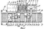
На фиг.1 приведено схематическое изображение части транспортера, используемого в устройстве согласно изобретению, вид спереди; на фиг.2 вид в плане устройства, изображенного на фиг.1; на фиг.3,4 соответственно вид в плане и увеличенный вид в плане, аналогичные виду на фиг.2, но с захватывающими головками на разных стадиях рабочего цикла; на фиг.5 и 6 - соответственно частичные виды сверху в увеличенном масштабе двух половин двойной матрицы; на фиг. 7,8 схематическое изображение штамповочного пресса для листовых термопластов на двух разных стадиях работы без ступенчатого транспортера; на фиг.9 вид снизу в увеличенном масштабе части захватывающей головки; на фиг.10-12 изображены детали фиг. 8 в увеличенном масштабе; на фиг.13 деталь фиг.1 в увеличенном масштабе; на фиг.14 вид, аналогичный виду на фиг.1, но на другой стадии рабочего цикла; на фиг.15 деталь фиг.14; на фиг.16 вид спереди укладчика, который может использоваться после ступенчатого транспортера во врем стадии загрузки; на фиг.17 деталь фиг.16 в увеличенном масштабе, показывающая прием, каким сформованные изделия укладываются в стопки; на фиг. 18 деталь фиг.16 в увеличенном масштабе; на фиг.19-вид укладчика в соответствии с фиг. 16 на стадии выгрузки на пластину; на фиг.20 деталь фиг.18, показывающая укладчик в положении, готовом для разгрузки; на фиг.21 вид укладчика в соответствии с фиг.16 в положении для горизонтальной разгрузки; на фиг.22,23 изображены схематически последовательные стадии горизонтальной разгрузки укладчика в соответствии с фиг.21; на фиг.24 изменение относительно фиг.14; на фиг.25 вид графика стадий формования и периодов цикла для оборудования, показанного на фиг.1-23; на фиг.26 схематический вид торцевой части и поперечное сечение части матрицы и части захватывающей головки в процессе захвата сформованного изделия; на фиг.27 вид детали фиг.26 в увеличенном масштабе; на фиг.28 вид аналогичный виду на фиг.27, но который показывает следующую стадию захвата кромки изделия головкой; на фиг.29 схематически боковой вид, показывающий изделие, которое не имеет плоской верхней кромки при захвате головкой, показанной на фиг.26-29; на фиг.30 схематический вид в разрезе другого варианта выполнения захватывающей и транспортирующей головки в процессе сближения со сформованным изделие, расположенным в матрице; на фиг. 31 вид снизу части захватывающей головки в соответствии с фиг. 30; на фиг.32 вид, аналогичный виду на фиг.30, но когда изделия находится в процессе извлечения из формы; на фиг.33 вид изделия, изображенного на фиг.32 после извлечения из формы, когда оно готово для транспортирования; на фиг.34 и 35 вертикальный вид и вид в разрезе изделия, показанного на фиг. 33, когда оно опущено на приемную модель на ступенчатом транспортере; на фиг. 36 вид другого варианта выполнения захватывающей и транспортирующей головки согласно изобретению в увеличенном масштабе в ходе извлечения изделия из формовочной матрицы; на фиг.37 и 38 изображена деталь фиг.36 в увеличенном масштабе в двух разных рабочих положениях; на фиг.39 вид другого варианта выполнения захватывающей и транспортирующей головки в ходе удаления сформованного изделия; на фиг.40 - изображена деталь фиг.39 в увеличенном масштабе в положении устройства, готовом для освобождения изделия; на фиг.41 и 42 виды другого варианта выполнения захватывающей и транспортирующей головки согласно настоящего изобретения в вертикальном виде и в разрезе. Figure 1 shows a schematic illustration of a part of the conveyor used in the device according to the invention, front view; figure 2 is a plan view of the device depicted in figure 1; figure 3.4, respectively, a plan view and an enlarged plan view, similar to the view in figure 2, but with exciting heads at different stages of the working cycle; 5 and 6 are respectively partial top views on an enlarged scale of the two halves of the double matrix; in FIG. 7.8 is a schematic illustration of a stamping press for sheet thermoplastics at two different stages of operation without a step conveyor; Fig.9 is a bottom view on an enlarged scale of part of the gripping head; 10-12 show details of FIG. 8 on an enlarged scale; in Fig.13 detail of Fig.1 on an enlarged scale; Fig.14 is a view similar to that of Fig.1, but at a different stage of the working cycle; on Fig detail of Fig; on Fig front view of the stacker, which can be used after the step conveyor during the stage of loading; on Fig a detail of Fig.16 on an enlarged scale, showing the reception of how molded products are stacked; in FIG. 18 is an enlarged detail of FIG. 16; FIG. 19 is a view of the stacker in accordance with FIG. 16 at the stage of unloading onto the plate; on Fig a detail of Fig, showing the stacker in a position ready for unloading; on Fig a view of the stacker in accordance with Fig in position for horizontal unloading; on Fig.23,23 shows schematically sequential stages of horizontal unloading of the stacker in accordance with Fig.21; on Fig change relative to Fig; on Fig a graph of the stages of molding and cycle periods for the equipment shown in figures 1-23; on Fig schematic view of the end part and the cross section of part of the matrix and part of the gripping head in the process of gripping the molded product; on Fig a detail view of Fig on an enlarged scale; on Fig a view similar to the view on Fig, but which shows the next stage of capturing the edge of the product head; on Fig schematically a side view showing a product that does not have a flat upper edge when capturing by the head shown in Fig.26-29; on Fig schematic view in section of another embodiment of a gripping and conveying head in the process of convergence with the molded product located in the matrix; in FIG. 31 is a bottom view of a portion of the pickup head in accordance with FIG. thirty; on Fig a view similar to that in Fig.30, but when the product is in the process of extraction from the mold; on Fig view of the product shown in Fig after removing from the mold when it is ready for transportation; on Fig and 35 a vertical view and a sectional view of the product shown in Fig. 33 when it is lowered onto a receiving model on a step conveyor; in FIG. 36 is an enlarged view of another embodiment of a gripping and conveying head according to the invention during removal of an article from a molding matrix; on Fig and 38 shows a detail of Fig on an enlarged scale in two different operating positions; on Fig a view of another embodiment of a gripping and conveying head during removal of the molded product; in Fig.40 - shows a detail of Fig.39 on an enlarged scale in the position of the device, ready to release the product; 41 and 42 are views of another embodiment of a gripping and conveying head according to the present invention in a vertical view and in section.
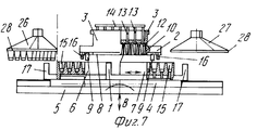
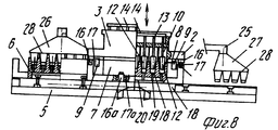
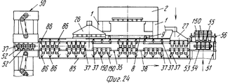
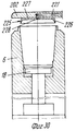
Устройство для термического формования полых изделий содержит пресс, включающий опорную конструкцию 1, на которой смонтирована неподвижная верхняя плита 2, несущая пуансон 3, который в приведенном примере также неподвижен, скользящий несущий матрицу стол 4, который смонтирован, например, на роликовых опорах, отвечающих высоким нагрузкам, с автоматической смазкой (не показано для выполнения горизонтальных перемещений (стрелка А), и нижняя плита 5, которая может перемещаться в вертикальном направлении (стрелка В, фиг. 7), которая приводится в движение, например, двумя блоками переключения (не показано). Подвижный стол 4 поддерживает две половины матрицы (двойную матрицу) 6 и 7, которые идентичны и расположены рядом друг с другом на одном уровне, которые перемещаются подвижным столом 4 попеременно под пуансон 3, где они поднимаются и взаимодействуют с пуансоном и последовательно открываются в результате опускания, чтобы перемещаться в боковом направлении относительно пуансона 3. Иначе говоря, половина 6 матрицы перемещается влево, а половина 7 матрицы перемещается вправо (как показано) относительно неподвижного пуансона 3. A device for thermally molding hollow articles contains a press, including a supporting structure 1, on which a fixed
Лист 8 термопластичного материала, который может быть намотан на сердечник или поступать непосредственно из экструзионного блока (не показаны), объединенного с устройством для термического формования, выполнен с возможностью продвигаться вперед посредством цепной подачи, обозначенной позицией 9, в направлении, перпендикулярном к направлению движения двойной матрицы под пуансоном 3, но над двойной матрицей ступенчато-синхронно с операцией штампования или формования. A
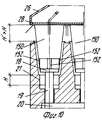
Пуансон 3 (фиг.7,8) может иметь множество углублений 10, каждое из которых имеет открытый нижний конец, ограниченный свободной кромкой 11 (фиг. 10 и 11), и включает соответствующий плунжер 12, закрепленный на конце соответствующего вертикального управляющего стержня 13, подвижно смонтированного между верхней стенкой пуансона и выходящий за пределы ее, чтобы встретиться и соединиться с верхним приводящим стержнем или пластиной 14, которая в свою очередь управляется средством приведения (не показан). Две половины 6 и 7 матрицы каждая имеет множество направленных вверх открытых полостей 15, равных по количеству числу углублений 10 и имеющих такое же расположение, так что при смыкании матрицы с пуансоном каждое углубление 10 или колодец точно совпадает с соответствующей полостью 15. The punch 3 (Fig.7.8) may have
Центрирующее средство, содержащее, например, четыре штыря 16, смонтированные на верхней плите 2, которые либо закреплены неподвижно, либо могут выдвигаться для вхождения с соответствующими приемными гнездами 17 в матрице, предусмотрено для правильного совмещения половин 6 и 7 матрицы с пуансоном 3 при их смыкании. A centering tool, containing, for example, four
Основание каждой полости 15 снабжено извлекающим устройством (фиг.7-12), содержащим головку 18, которая может перемещаться вверх, так как управляется соответствующим стержнем 19, выполненным заодно с управляющей планкой или пластиной 20, которая предназначена освобождать и выталкивать одно или больше сформованных изделий 150 из пресса после разведения формовочных форм. The base of each
Предпочтительно, чтобы каждая полость 15 имела сужение 21, образующее ступень вокруг сформованного изделия, высота которой от основания полости определяет высоту H стопы сформованных изделий 150 (фиг.10). Preferably, each
Нижняя плита 5 приводится в движение соответствующими устройствами (не показано), например, двумя блоками переключения для осуществления вертикальных движений между половинами 6 и 7 матрицы и пуансоном 3 для закрытия и открытия пресса. The
Два эксцентрика, которые, заставляя плиту 5 перемещается на небольшие расстояния, дают возможность вырезать и отделять изделия от листа, могут быть смонтированы ниже основания двух блоков переключения. Эта операция, как принято в этой области техники, осуществляется во время смыкания половин 6, 7 матрицы с пуансоном 3. Two eccentrics, which, forcing the
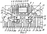
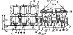
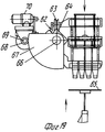
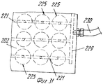
Неподвижная верхняя плита 2 имеет две вертикальных опорных колонны 22 и 23 (фиг.2-4), на каждой из которых смонтирован с возможностью вращения соответствующий выступающий рычаг 24, 25, который на своем свободном конце несет всасывающую захватывающую голову 26, 27, которая выполнена, например, в форме колокола, который закрывается у основания перфорированной всасывающей пластиной 28, сообщающейся с источником вакуума или отрицательного давления, для того, чтобы отсасывать воздух, как отсасывающий насос (не показан) посредством гибкого шланга 26а и 27а. Пластина 28 (фиг.9) имеет множество сквозных отверстий 29, расположенных в правильном порядке на расстоянии от пересечения продольной 30 и поперечной 631 всасывающих канавок преимущественно с интервалом, равным интервалу полостей 15 в половинах 6 и 7, матрицы. The fixed
Рычаги 24 и 25 расположены соответственно на одной стороне пуансона 3 и совершают угловые перемещения относительно колонн 22 и 23 между положением, при котором соответствующая захватывающая головка 26 и 27 находится над соответствующей половиной 6 или 7 матрицы, когда она перемещается полностью в боковую сторону от пуансона 3, и положением снаружи устройства для герметического формования, осуществляемые посредством соответствующего блока 32, 33 двигателя/редуктора, приводимого таким образом, чтобы побудить захватывающие головки 26, 27 делать ритмичные угловые движения синхронно с попеременными движениями вперед и назад половин 6 и 7 матрицы для осуществления транспортирования сформованных изделий 150, как будет подробнее описано ниже. The
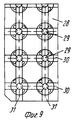
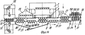
В радиусе действия рычагов 24 и 25 расположен ступенчатый транспортер 35 (фиг. 1-3,13,14), который образован из двух скользящих и несущих сторон или лент 36, на которых подвижно смонтировано множество пластин или моделей 37, приводимых в движение на их двух противоположных концах парой цепей 38, которые проходят вокруг пары звездочек 39 на концах транспортера (фиг.13). Каждая пластина или модель 37 имеет промежуточную ось 40, обеспечивающую шарнирное движение цепи 38, и два боковых валика или пальца 41 и 42 на каждой своем конце, которые входят в зацепление с цепями. Вдоль лент 36 свободно установлены валики 41 и 42 или могут двигаться вдоль соответствующих прямых верхней 43 и нижней 44 направляющих или реек, тогда как на трансмиссионном конце транспортера палец 40 следует по круговой траектории вокруг колеса 39, а передний валик (по отношению к направлению движения, например, валика 41 на фиг.13), следует также по круговой траектории вдоль соответствующей неподвижной направляющей 45, которая имеет тот же радиус кривизны, как и первоначальная кривизна колеса 39, и задний валик (валик 42 на фиг.13) входит в зацепление между двух обработанных по радиусу зубцов 46 колеса 47, которое имеет свою ось вращения вдоль линии колеса 39 и указанной линии шага. При такой конструкции на концах транспортера 35 каждая пластина или модель 37 возвращается в положение, которое всегда параллельно другим пластинам или моделям, и когда находится в разгрузочном положении, то она относительно далеко отстоит и от пластины или модели, которая предшествовала ей, и которая следует за ней. Within the radius of action of the
Поэтому можно создать рабочую позицию обработки 50 (фиг.1,14) и рабочую позицию 51 укладки в стопы на трансмиссионных концах транспортеров 35, и возможные рабочие позиции обработки, как будет описано ниже. Therefore, it is possible to create a working position for processing 50 (Fig. 1.14) and a working
Рабочая позиция 50 предназначена выполнять различные операции со сформованными изделиями 150, которые расположены в легко доступном положении для рабочих узлов, предусмотренных на этой рабочей позиции, тогда как на позиции 52 укладки в стопы сформованные изделия могут укладываться до окончательного удаления с транспортера 35. The working
Пластины или модели 37, каждая, имеют множество отверстий или гнезд 38 того же диаметра (или немного меньшего) и с таким же разнесением друг от друга, как полости 15 в половинах 6 и 7 матрицы так, что они могут принимать изделия, полученные после формования и переданные им головками 26 и 27. Пластины или модели 37 перемещаются ступенчато по верхнему тракту вдоль транспортера 35, вдоль которого они принимают сформованные изделия 150 попеременно от головок 26 и 27, останавливаются затем последовательно в рабочей позиции обработки 50, а затем проходят по нижнему тракту, чтобы достигнуть позиции укладки 51. The plates or
Позиция 50 может быть предназначена для выполнения любой требуемой дополнительной операции, такой, например, как перфорирование оснований сформированных изделий 150, сухая печать или проставление штампов на изделиях, маркировка, наполнение растворимыми порошками для приготовления напитков, стерилизация и т.д.
На фиг.1 и 14 позиция 50 показана в качестве примера в виде сверлильной головки, приводимой в действие тумблером, снабженным сверлами 52, расположенными с тем же интервалом, как отверстия 37а и модели 37 и функционирующие в том же рабочем ритме, как и ступенчатый транспортер 35. 1 and 14,
Однако любое другое соответствующее рабочее устройство, способное выполнять требуемый процесс или манипуляцию со сформованными изделиями, может быть предусмотрено вместе или во взаимодействии с блоками в рабочей позиции 50, приводимыми в действие тумблерами. However, any other appropriate working device capable of performing the required process or manipulation of the molded products may be provided together or in conjunction with the blocks in the working
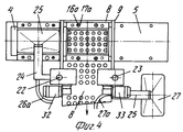
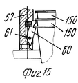
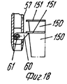
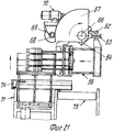
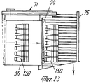
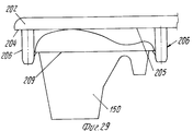
Позиция 51 для укладки в стопы (фиг.1 и 14-21) содержит опорную раму 53, на которой расположен (по ходу движения) конец транспортера 35, нижний толкатель 54, который может приводиться в вертикальное движение попеременно вперед и назад синхронно со ступенчатым перемещением транспортера 35 и имеет множество головок 55 толкателя, число которых равно числу отверстий 37а в моделях 37 и те же интервалы между собой, как и отверстия 37а, и укладчик 56, расположенный над транспортером 35 в вертикально центрированном положении относительно толкателя 54. Укладчик 56 может быть любого подходящего типа, например, имеющим множество параллельных трубчатых стержней 57, удерживаемых вместе каркасом 58 (фиг.16), на котором также подвижно смонтирован верхний толкатель 59, который также может приводиться в возвратно-поступательное движение, что будет описано ниже.
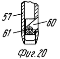
Каждый стержень 57 предпочтительно снабжен зубками 60 (фиг.18,20), которые способны втягиваться благодаря тому, что они шарнирно вращаются вокруг поперечной оси 61, так что они могут перемещаться под углом между положением, при котором они втянуты в стержень (фиг.20) так, что изделия 150 могут перемещаться между стержнями, и положением, при котором они выступают из стержней (фиг.18) для взаимодействия с кромкой 151 изделия 150. Each
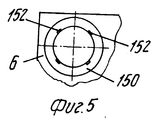
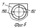
Как видно на фиг.5,6 и 17, можно расположить компоненты таким образом, что половина 6 матрицы формирует изделия идентичные тем, что формуются в половине 7 матрицы, но имеющие, например, четыре опоры или углубления 152, смещенные на заданный угол таким образом, что если стопы на рабочей позиции 51 образуются из изделий, поступающих от половины 6 матрицы и половины матрицы 7 поочередно, так как они загружаются на модели 37 транспортера 35, плоская часть основания изделия 150 (даже когда нижняя кромка имеет относительно большой соединяющий угол) всегда приводится в положение, в котором она опирается на достаточное число опор 152. As can be seen in FIGS. 5,6 and 17, it is possible to arrange the components in such a way that the
Аналогичный результат достигается в случае, если вместо опор 152 с разной угловой ориентацией в двух половинах матрицы предусмотрено другое количество опор 152. Это естественно дает возможность постоянно иметь отличный укладчик без риска постоянного или необратимого прилипания изделий 150 друг к другу, тем самым снижая количество брака. A similar result is achieved if instead of the
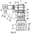
Укладчик 56 устанавливается на тележке 62, которая может перемещаться посредством колес 63 вдоль поперечины или секции 64 для транспортировки множества стоп изделий 150 от укладчика 56, например, на несущую или опорную поверхность 65, которая при необходимости может подниматься и опускаться, как показано схематически на фиг.16 и 19. The
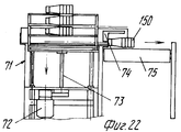
Поперечина 64 может быть установлена с возможностью вращения вокруг своей продольной оси 66 и может иметь угловые выступы вокруг нее в зубчатой секции 67, которая входит в зацепление с шестерней 68, посаженной на приводной вал 69 блока двигателя редуктора 70. При таком монтаже укладчик 56 может наклоняться на угол 90o или любой другой промежуточный угол, и тем самым устанавливаться в горизонтальное положение и опускаться вниз на опорную платформу 71 (фиг.21-23). Платформа 71 способна выполнять ступенчатое нисходящее движение (через трансмиссию 72, винт 73 и соответствующую гайку) для создания возможности поперечному выталкивателю 74 переносить ряд уложенных в стопу изделий 150 на гнездовой транспортер 75, который передает уложенные изделия, например, на место упаковки.The
Способ термического формования полых изделий, реализуется при работе устройства. Когда пресс открыт, заданная длина листа 8 продвигается вперед посредством цепной подачи 9 под неподвижным пуансоном 3, после чего половина 6 или 7 матрицы (например, 6), которая расположена под пуансоном 3, поднимается и смыкается с пуансоном 3 в результате чего происходит формование изделий 150 и последующее их вырезание. Половина 6 матрицы вместе с половиной 7 матрицы движутся вниз, чтобы открыть пресс, и сразу после этого несущий половины матрицы стол 4 перемещается вбок, так чтобы отвести половину 6 матрицы полностью в сторону от пуансона 3 и половину 7 матрицы подвести под пуансон 3 в положение готовности для следующего цикла термического формования. The method of thermal molding of hollow products, is implemented when the device. When the press is open, the predetermined length of the
Тем временем захватывающая головка 26 перемещается в зону извлечения изделий над половиной 6 матрицы, у которой теперь нет никаких препятствий и как только половина 7 матрицы смыкается с неподвижным пуансоном 3, головка извлекает сформованные изделия 150 из половины 6 матрицы, которые были предварительно извлечены или освобождены из ячеек 15 головками 18 устройства извлечения. Вращаясь вокруг своей колонны 22 (фиг.2), головка 26 перемещается над моделью 37 на транспортерной ленте 35 опускает сформированные изделия 150 в соответствующее число отверстий 37а (фиг.2,3). В последующем цикле формования захватывающая головка 27 движется над половиной 7 матрицы, которая передвинулась вбок по отношению к пуансону 3 в зону извлечения, и при движении, аналогичном движению головки 26 переносит сформованные изделия аналогичным образом из половины 7 матрицы модели 37 на транспортер 35. В результате головка 27 будет помещать изделия 150 на чередующиеся модели на транспортере. То же самое будет проделано захватывающей головкой 26, но на модели, оставленные незанятыми головкой 27, так что все модели 37 в конечном счете будут заполнены изделиями 150, прежде они будут подаваться на позицию окончательной обработки 50. Meanwhile, the gripping
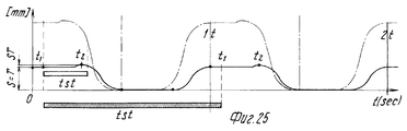
Следует отметить тот факт, что каждое сформованное изделие транспортируется ступенчатым транспортером 35 и остается тем, тем самым давая возможность продлить время tst стабилизационного процесса, вынося его за рамки нахождения изделия в прессе, что является положительным фактором в улучшении качества формуемых изделий 150. Фактически в приведенном примере изделия 150 находятся на моделях транспортера 35 в течение семи или больше циклов термического формования. It should be noted that each molded product is transported by a
Время от времени можно брать контрольные образцы изделий 150 с модели 37, выбранной случайно для проверки качества изделий 150 без внесения какого-либо нарушения в рабочий цикл оборудования. From time to time, it is possible to take control samples of
На рабочей позиции 50 изделия обрабатываются или частично заполняются порошковым материалом, или маркируются и т.д. и затем пропускаются вдоль нижней части транспортера 35 в сторону позиции 51 укладки, из которой они удаляются в виде стоп, подаваемых для использования или на упаковочную установку для поставки. Далее во время движения вдоль нижней части транспортера, они подвергаются продолжительной стабилизации и остаются в тех же относительных положениях, какие они имели в штамповочном прессе. At
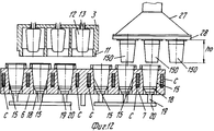
Следует отметить, что дополнительно к обеспечению легкого и равномерного управления внутренним отрицательным давлением по всей рабочей поверхности пластины 28, всасывающие захватывающие головки 26 и 27 могут применяться во всех случаях независимо от наличия кромки 151 на изделиях, которые захватываются. В отличие от традиционных систем, благодаря использованию головок 26 и 27 движение для извлечения изделий 150 из пресса равно высоте H укладки (фиг.10). It should be noted that in addition to providing easy and uniform control of internal negative pressure over the entire working surface of the
Более конкретно, обращаясь к фиг. 11, когда половины 6 или 7 матрицы (например, 6) перемещаются в положение извлечения или разгрузки, головка 26 перемещается в положение над половиной 6 матрицы в то же самое время, как уже было сказано. Время, в течение которого устройство извлечения 18 и 20 должно пройти расстояние hо для частичного извлечения изделий 150 перед захватом их головкой 26, соответствует времени, когда часть 7 пресса совершает другой цикл термического формования. Это также справедливо в отношении последующих движений извлечения головкой 27, в отношении ее вращения и размещения изделий 150 и моделей 37 и в отношении ее возвращения в положение над матрицей 7, так что мертвый ход не добавляется ни к одному из циклов формования.More specifically, referring to FIG. 11, when the
Это означает, что резко уменьшаются периоды ожидания, в течение которых, пресс открыт, которые, как сказано выше, со ссылкой на устройства для термического формования со всасывающей пластиной, входящей в зону прессования или формования, составляют 30% цикла формования. This means that the waiting periods during which the press is open, which, as mentioned above, with reference to devices for thermal molding with a suction plate included in the pressing or molding zone, comprise 30% of the molding cycle, are sharply reduced.
Следует также отметить, как удаление изделий 150 только частично происходит благодаря движению головок или оснований 18. Изделия фактически удаляются (фиг.12) посредством движения, отделяющего матрицы от пластины, частично вызываемого опусканием матрицы и частично поднятием оснований 18. Так как эти движения происходят одновременно с другими мертвыми ходами в каждом цикле формования, они не влияют на производительность оборудования. It should also be noted that the removal of
Если провести сравнение с известной машиной, можно отметить что если
ho есть высота изделий 150,
hp высота управляющей пластины 20,
ha длина пути при укладке, и
hs размер (высота) двойной матрицы 6,7, то общая высота H половинок 6 и 7 на фиг. 11 согласно настоящему изобретению равна H=hp+ho+hs, т.е. H не меньше, чем величина, равная по меньшей мере максимальной высоте формуемых изделий 150. Так как высота Ho матрицы в традиционной машине с укладкой в стопы обычно немного больше, чем двойная высота формуемых изделий, то можно сделать вывод, что извлечение, производимое головками 26 и 27 в соответствующих зонах извлечения или разгрузки, полностью происходит вне зоны формования и в стороне от пуансона 3, по меньшей мере на расстоянии в половину высоты половин 6 и 7 матрицы.If you make a comparison with a known machine, it can be noted that if
h o is the height of the
h p the height of the
h a laying distance, and
h s the size (height) of the double matrix is 6.7, then the total height H of the
Уменьшение высоты половин матрицы ведет к значительному уменьшению их веса и тем самым их инерции, что означает, что боковые перемещения могут выполняться быстрее. Reducing the height of the halves of the matrix leads to a significant reduction in their weight and thereby their inertia, which means that lateral movements can be performed faster.
Также видно на фиг.11, что половина 7 матрицы показана в положении извлечения или разгрузки. Тот факт, что половина 7 матрицы перемещается в положение полностью за пределами зоны прессования ил формования, позволяет выбирать размеры всасывающих головок 26 и 27 таким образом, чтобы сумма потоков (Q1+Q2+Q3) вся походила через сечение Hpe. В сечениях S1, S2, и S3 значения расходов будут идентичны, и поэтому величина давления P, которая устанавливается в головке, будет одинаковой по всей поверхности пластины 28. В результате происходит оптимизация наиболее важного параметра для нормальной работы захватывающей головки 26, 27 так, что становится возможным достигнуть оптимального условия, при котором Q1=Q2=Q3.It is also seen in FIG. 11 that half of the
Описанное выше изобретение может быть подвергнуто многочисленным модификациям и изменениям в объеме изобретения. Так, например, транспортер 35 может быть заменен транспортером с пустым возвратным трактом или с пустыми моделями 37 после прохождения вокруг конечного возвратного колеса значительного диаметра или нескольких возвратных колес, таким образом, что установки на рабочих позициях 50 и 51 могут функционировать на своем верхнем тракте. Рабочих позиций обработки 50 может быть больше одной и они могут быть расположены последовательно вдоль транспортера. The invention described above may be subjected to numerous modifications and changes in the scope of the invention. So, for example, the
При необходимости позиция 50 может быть исключена из конструкции или в любом случае может бездействовать в случае определенных типов изделий 150. If necessary, the
Далее, как показано на фиг.14 и 24, всасывающий колпак 80 для летучих остатков, образующихся из термопластичного материала А, используемого для формования изделий 150, может быть смонтирован в любом удобном положении выше, вокруг или ниже транспортера 35. Камера 85 обработки в виде туннеля, например, для стерилизации и/или тепловой обработки, которая может охватывать по крайней мере один участок транспортера 35 и которая может быть снабжена множеством игл 86, предназначенных для впрыска текучей среды, такой как холодный воздух, чтобы достигнуть оптимальной стабилизации изделий 150 снаружи пресса, что также схематически показано на фиг.24. Further, as shown in FIGS. 14 and 24, the
При необходимости за каждой захватывающей головкой 26 и 27 предусматривается рабочая позиция для образования спиральных ободков или закраин на всех изделиях, сформованных в течение одной и той же операции формования сразу после того, как они были разгружены на пластину или модель 37. В этом случае транспортер 35 имеет соответственно большую длину, по меньшей мере, на две пластины или модели, что дает возможность формования изделий со спиральным ободком или закраиной в течение времени цикла, когда изделия еще горячие, как только они вынуты из моделей 6 или 7, без необходимости нагревать их для операции отделки ободка или закраины до достижения рабочей позиции 50. If necessary, a working position is provided for each
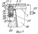
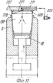
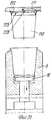
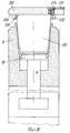
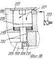
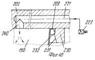
Ссылаясь на фиг.26-29, следует отметить, что захватывающая и передающая головка согласно изобретению содержит захватывающее устройство 201, образованное из подвижной пластины 207 или жесткого сетчатого элемента, который смонтирован, например, на одном рычаге 24 или 25. Подвижная пластина 202 имеет плоскую нижнюю поверхность 204, на которой расположены одно или больше гнезд 205, каждое из которых ограничено по меньшей мере двумя зацепляющими (расцепляющими) блоками 206, которые выступают с поверхности 204 пластины. Referring to FIGS. 26-29, it should be noted that the pick-up and transfer head according to the invention comprises a pick-up
Каждый зацепляющий/расцепляющий блок 206 содержит выступ или муфту 207, которая закрыта у основания, один конец которой прикреплен, например, привинчен, к поверхности 204 пластины, тогда как другой конец 208, свободный и предпочтительно овальной или скошенной формы для образования средства зацепления с фланцевой кромкой 209, представляющий собой плоский нижний заплечик сформованного изделия 150, такого как стакан, полученный путем формования листового термопласта в половине 6 или 7 матрицы, которая снабжена выталкивающим основанием или основаниями или подвижными извлекающими устройствами 18. Each engaging / disengaging
В части своей стенки, обращенной к соответствующему гнезду 205, каждый зацепляющий/расцепляющий блок 206 имеет продольную щель 213, которая проходит по оконечной части длины муфты 207, через которую может выступать свободный конец зубка 214, который зацепляется с заплечиком 209. Зубец 214 смонтирован шарнирно на верхней части, как показано позицией 215, диаметрально оси, которая с возможностью вращения вокруг перпендикулярна к продольной оси муфты и к осевой плоскости щели 213. Ось 215, в свою очередь, поддерживается придатком 216 поршня 217, который смонтирован подвижно и герметично в муфте 207 с помощью уплотнения, такого как уплотнительное кольцо 218. Под зубцом 214 предусмотрена небольшая пластина 219, которая скользит в муфте 207, у которой верхняя торцевая поверхность, входящая в контакт с зубцом 214, представляет собой плоскость наклонную в сторону щели 213, а нижняя торцевая поверхность находится в контакте с возвратной пружиной 220, которая прижимает закрытый конец муфты. In the part of its wall facing the corresponding
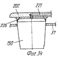
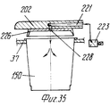
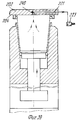
В верхней части каждая муфта 207 сообщается через соответствующий канал 221, например, образованный в толщине пластины 20 (и в этом случае пластина 202 может также действовать как питающая линия) или образованного из гибкого шланга, с источником текучей среды (воздуха) под давлением (не показано) содержащего трехходовой управляющий электрический клапан 223. Таким образом, когда клапан 223 пропускает сжатый воздух к зацепляющим-расцепляющим блокам 206 (фиг.28), их поршни 217 перемещаются вниз в соответствующих муфтах 207, воздействуя на возвратные пружины 220, тем самым принуждая нижние конусообразные концы зубьев 214 выступать наружу и входить в горизонтальное зацепление с опорной частью кромки изделия 150. Изделие 150 таким образом прижимается к захватывающей пластине 202, в результате чего его можно удалить из половины 6 или 7 матрицы и транспортировать в полной безопасности, не подвергая деформации, перекашиванию или повреждению другого рода на приемную установку, как например, удерживающую модель (обозначенную позицией 22 на фиг. 34,35), расположенную на транспортере 35. На приемной позиции управляющий клапан 223 выпускает сжатый воздух, который недавно был подан через канал 221 (фиг.27), в результате чего возвратная пружина 220 заставляет небольшую пластину 219 снова подняться и это, в свою очередь, заставляет зубец 214 вернуться в муфту небольшой пластиной и зубцом, и в это же время перемещает поршень 217 вверх. Изделие 150 тем самым освобождается от захватывающей головки 207 и может падать в сборник. In the upper part, each
Важно отметить, что при использовании описанной выше захватывающей и передающей головки необязательно, чтобы формуемые изделия 150 имели круглую форму, такую как стакан, или форму правильного многоугольника, как кювета, они могут иметь любую требуемую форму, например, сплющенную или вытянутую, как показано на фиг. 37, но с заплечиком 209, который может быть сплошным или с разъемными, и даже со сплошным заплечиком, не лежащим в одной плоскости (в последнем случае зацепляющие/ расцепляющие устройства 206 могут быть выполнены так, чтобы действовать на разных уровнях относительно друг друга). Кроме того, изделие 150 может быть значительно ширины, и в этом случае будет достаточно образовать достаточное число зацепляющих/расцепляющих устройств 206 для каждого гнезда 205. It is important to note that when using the gripping and transmitting head described above, it is not necessary that the molded
Захватывающая и передающая головка, описанная выше, работает очень просто и быстро. Когда формовочный пресс открыт, пластина 202 перемещается ниже половины 6 или 7, опускаясь на изделия 150, как показано на фиг.27, и опирается на изделие. Электрический клапан 223 пропускает сжатый воздух в зацепляющие/расцепляющие блоки 206, которые тогда принимают конфигурацию, показанную на фиг.28, т.е. они подводят свои зубцы 214 в положение для зацепления с заплечиком изделия или изделий, которые тем самым прижимаются к пластине. После передачи изделий на сборник электрический клапан 223 выпускает сжатый воздух, в результате чего удерживающие зубцы 214 отводятся и втягиваются в соответствующие муфты 207, так что изделия освобождаются и падают в приемный коллектор. The gripping and transmitting head described above works very simply and quickly. When the molding press is open, the
В варианте выполнения настоящего изобретения, показанном на фиг.30-35, зацепляющие/расцепляющие средства, соединенные с захватывающей пластиной 202, содержат чашу 225, расположенную, так, чтобы взаимодействовать с гнездом или гнездами 205, которая имеет периферическую конусную кромку 226 из упруго деформирующегося материала. Кромка 226 предназначена проникать в полое сформированное изделие 150, подвергаясь деформации, даже если изделие не имеет фланцевой кромки, и упруго сцепляться с внутренней стенкой (фиг.32) достаточно прочно, чтобы иметь возможность удалить изделие из матрицы 6 или 7 (фиг.33) и передать его на модель 37 сборника (фиг.34). In the embodiment of the present invention shown in FIGS. 30-35, the engaging / disengaging means connected to the
Основание 227 чаши 225 имеет по меньшей мере одно отверстие 228, которое сообщается с каналом 221, который, в свою очередь, сообщается с источником сжатого воздуха (не показано) через трехходовой электрический управляющий клапан 223, который образует выпускное отверстие для выпуска воздуха в атмосферу из внутреннего пространства в изделии 150, когда чаша 225 проникает в изделие 150, и посылает импульс (струю) сжатого воздуха в изделие (фиг. 35), когда оно находится в приемной модели 222, тем самым отпуская кромку 226 и освобождая ее. The
Если образовано множество гнезд 205 на захватывающей пластине 202, отдельные каналы 221 могут быть соединены с магистралью 229 (фиг.31), в которую, в свою очередь, подается сжатый воздух через канал 230 прямо от источника сжатого воздуха и задерживается клапаном 223. If a plurality of
Конечно, вместо чашки 225 может быть использовано упругое кольцо, образованное только кромкой 226, соединенное с плоской поверхностью 204 головки 202. Of course, instead of a
Фиг. 36-38 показывают еще один вариант выполнения захватывающей головки 202, в котором кольцо или по меньшей мере два противолежащих кольцевых отрезка 230, расположенные концентрически вокруг соответствующего гнезда 205, образованы у каждого гнезда 205. Этот вариант, в частности, предпочтителен когда формуются изделия 150, которые могут иметь кромки, но которые по некоторым причинам не совсем хорошо опираются на плоскую поверхность 204 пластины 202. FIG. 36-38 show yet another embodiment of a
Кольца или кольцевые отрезки 230 имеют свои внутренние стенки, образованные отрезком 231, который выступает в сторону изделия, которое должно быть зацеплено, и отрезком 232, который направлен в сторону пластины 202. При такой конфигурации, когда пластина 202 опускается на изделия 150 в матрице 6 или 7, внутренние губы 209а кромок 209 сначала скользят вдоль выступающего отрезка 231 и затем отгибаются слегка назад на себя и принимают упругую нагрузку, подвергаясь тем не менее одновременно деформации, которая не выходит за предел упругости материала, из которого они выполнены и затем вдоль отрезка 232, где они могут немного расширяться, и опирается на пластину 202, оказываясь тем самым зажатым внутри кольца или кольцевого отрезка 230. Rings or
Вдоль кромочной линии 209 предусмотрено одно или больше выталкивающих устройств 234, каждое из которых образовано поршнем 235, соединенным с валом 236, подвижно установленным в отверстии 237, образованном, например, в пластине 202. Отверстие 237 образует проход для вала 236 в плоской поверхности 204 пластины 202 тогда как другой конец может быть герметизирован пластиной 238. Поршень 235 подпружинен возвратной пружиной 239 со стороны плоской поверхности и то время, как он также сообщается через канал 221 с источником сжатого воздуха через трехходовой электрический управляющий клапан 223 (фиг. 37). Along the
Таким образом, для освобождения изделия 150 от пластины 202, все, что для этого требуется, это пропустить струю сжатого воздуха через канал 231, и она, действуя против пружины 239, опустит поршень 235, и его вал 236 тогда прижмет кромку 209 к наружной части кольца или кольцевых отрезков 230 (фиг. 38). Thus, to release the
В варианте, показанном на фиг.39,40, образовано одно или больше отверстий 240, сообщающихся с источником сжатого воздуха (не показан) через канал 221 и электрический управляющий клапан 223, вместо выталкивающих устройств 234. Изделие 150 удерживается у пластины 202 посредством упругого захвата его кромки 209, как в примере, показанном на фиг.36,38, но кромка 209 уплотнена кольцом 220. Чтобы вытолкнуть изделие 150, клапан 223 устанавливает 221 в сообщающееся положение с источником сжатого воздуха на момент времени, и таким образом посылает импульс воздуха в изделие, что выталкивает его из формы. In the embodiment shown in Fig. 39.40, one or
Фиг.41 и 42 показывает вариант выполнения, в котором средство зацепления/расцепления представляет собой расширяющийся мешок 250, который может быть вставлен в изделие 150 в опавшем состоянии и затем подвергнуться расширению путем надувания, пока не войдет в контакт с внутренними стенками изделия. Для этой цели расширяющийся мешок может содержать упругую мембрану, удерживаемую в положении против поверхности гнезда 20, например, посредством винтов 251 и прокладок 252, расположенных между крепежной пластиной 253 с пластиной 202 и небольшой удерживающей пластиной 254, так что мешок может расширяться и прижиматься своими боковыми стенками к внутренним стенкам изделия 150. Figs. 41 and 42 show an embodiment in which the engaging / disengaging means is an expanding
Внутренняя часть мембраны может быть соединена с источником сжатого воздуха через отверстие 240, канал 221 и трехходовой электрический управляющий клапан 223 для вдувания воздуха во время стадии захватывания и в состояние сообщения с атмосферой, чтобы выпускать воздух, тем самым отпуская изделие 150 в рабочей позиции накопления после извлечения и подачи из половины 6 и 7 матрицы. The interior of the membrane can be connected to a source of compressed air through an
Описанная выше захватывающая и передающая головка может быть подвергнута многим модификациям и изменениям в рамках настоящего изобретения. The gripping and transmitting head described above can be subjected to many modifications and changes within the scope of the present invention.
Так например, пластина 202 может быть заменена трафаретным устройством с ячейками, соединенными с соответствующим гибким каналом 221. So, for example, the
Дополнительно к этому упруго деформирующийся элемент 250 может подвергаться расширению и сжатию с помощью механических средств вместо пневматических, например, с помощью расширяющихся сегментов, управляемых коническим компонентом, управляемым стержневым устройством. In addition, the resiliently deforming
Claims (38)
Applications Claiming Priority (2)
| Application Number | Priority Date | Filing Date | Title |
|---|---|---|---|
| ITVR92A000012 | 1992-02-03 | ||
| ITVR920012A IT1257010B (en) | 1992-02-03 | 1992-02-03 | PROCESS AND EQUIPMENT FOR THERMOFORMING AND STACKING OF CABLE OBJECTS WITH BOTTOM STARTING FROM THERMOPLASTIC TAPE MATERIAL. |
Publications (2)
| Publication Number | Publication Date |
|---|---|
| RU93004492A RU93004492A (en) | 1996-11-27 |
| RU2080262C1 true RU2080262C1 (en) | 1997-05-27 |
Family
ID=11427455
Family Applications (1)
| Application Number | Title | Priority Date | Filing Date |
|---|---|---|---|
| RU9393004492A RU2080262C1 (en) | 1992-02-03 | 1993-02-02 | Method and apparatus for thermal molding of hollow objects with thermoplastic material sheet as their basis |
Country Status (36)
| Country | Link |
|---|---|
| US (3) | US5453237A (en) |
| JP (1) | JP2805571B2 (en) |
| KR (1) | KR100221232B1 (en) |
| CN (1) | CN1089058C (en) |
| AR (1) | AR247845A1 (en) |
| AT (1) | AT409107B (en) |
| AU (1) | AU655344B2 (en) |
| BE (1) | BE1005832A5 (en) |
| BG (2) | BG61599B1 (en) |
| BR (1) | BR9300392A (en) |
| CA (1) | CA2087512C (en) |
| CH (1) | CH689716A5 (en) |
| CZ (1) | CZ291995B6 (en) |
| DE (3) | DE4224009B4 (en) |
| DK (1) | DK174498B1 (en) |
| ES (1) | ES2068741B1 (en) |
| FI (1) | FI107033B (en) |
| FR (1) | FR2686827A1 (en) |
| GB (1) | GB2263660B (en) |
| GR (1) | GR1002588B (en) |
| HU (1) | HU214563B (en) |
| IL (1) | IL104556A (en) |
| IT (1) | IT1257010B (en) |
| LU (1) | LU88216A1 (en) |
| MX (1) | MX9300581A (en) |
| NL (1) | NL193860C (en) |
| NO (1) | NO304973B1 (en) |
| PL (1) | PL170936B1 (en) |
| PT (1) | PT101192B (en) |
| RO (1) | RO109440B1 (en) |
| RU (1) | RU2080262C1 (en) |
| SE (1) | SE512486C2 (en) |
| SK (1) | SK283495B6 (en) |
| TR (1) | TR26597A (en) |
| TW (1) | TW340090B (en) |
| ZA (1) | ZA93704B (en) |
Cited By (2)
| Publication number | Priority date | Publication date | Assignee | Title |
|---|---|---|---|---|
| RU2457185C1 (en) * | 2011-02-11 | 2012-07-27 | Открытое акционерное общество "Обнинское научно-производственное предприятие "Технология" | Device for extrusion of hollow glass articles |
| RU2587452C2 (en) * | 2010-07-08 | 2016-06-20 | Баццика Инджиниринг С.Р.Л. | Method of loading mould into moulding machine for moulding parts from foamed plastic and unloading mould from machine |
Families Citing this family (54)
| Publication number | Priority date | Publication date | Assignee | Title |
|---|---|---|---|---|
| US5919496A (en) * | 1992-10-28 | 1999-07-06 | Isap O.M.V. Group Spa | Flanging apparatus particularly for hollow articles obtained by thermoforming sheet material |
| IT1257683B (en) * | 1992-10-28 | 1996-02-01 | Pietro Padovani | EDGE BANDING MACHINE PARTICULARLY FOR CABLE ITEMS OBTAINED BY THERMOFORMING STARTING FROM THERMOFORMABLE RIBBON MATERIAL |
| IT1262775B (en) * | 1993-01-12 | 1996-07-04 | Isap Omv Group Spa | HEAD OF COLLECTION AND TRANSFER OF CABLE OBJECTS, PARTICULARLY FOR THERMOFORMING EQUIPMENT |
| IT1268286B1 (en) * | 1994-09-14 | 1997-02-27 | Isap Omv Group Spa | THERMOFORMING EQUIPMENT FOR THERMOFORMABLE MATERIALS IN TAPE OR SHEET |
| FR2732002B1 (en) * | 1995-03-23 | 1997-06-06 | Sidel Sa | ONLINE BOTTLING PLANT |
| US5720992A (en) * | 1995-10-19 | 1998-02-24 | Trafalgar House Company | Movable extractor plate assembly for rapidly removing articles from a thermoforming apparatus |
| US5795535A (en) * | 1996-03-15 | 1998-08-18 | Sencorp Systems, Inc. | Method of thermoforming plastic articles |
| IT1289111B1 (en) * | 1996-05-28 | 1998-09-25 | Isap Omv Group Spa | EQUIPMENT FOR COLLECTING AND PROCESSING THERMOFORMED OBJECTS FROM A THERMOFORMING MACHINE |
| US5788999A (en) * | 1996-07-04 | 1998-08-04 | Fuji Photo Film Co., Ltd. | Disk producing apparatus for a photo film cassette |
| NL1004837C2 (en) * | 1996-12-19 | 1998-06-22 | O T B Engineering B V | System for the production of optical data carriers. |
| DE19716655C2 (en) * | 1997-04-21 | 2002-11-21 | Gabler Gmbh Maschbau | Device for molding, punching and stacking deep-drawn parts made of thermoplastic |
| IT1293955B1 (en) * | 1997-06-13 | 1999-03-11 | Isap Omv Group Spa | PLATE DEVICE FOR PICK UP AND REMOVAL OF A PRINT OF THERMOFORMED OBJECTS FROM A THERMOFORMING PRESS |
| US6135756A (en) * | 1997-06-13 | 2000-10-24 | Arends; Albert W. | Differential pressure forming, trimming and stacking apparatus |
| US6264050B1 (en) | 1998-10-06 | 2001-07-24 | Plastipak Packaging, Inc. | Container with improved neck portion and method for making the same |
| IT1304212B1 (en) * | 1998-10-21 | 2001-03-13 | Isap Omv Group Spa | THERMOFORMING PLANT WITH MASK CONVEYOR. |
| DE29911272U1 (en) * | 1999-06-30 | 2000-11-16 | Stefan Maier Werkzeugbau Und M | Machine for row deep drawing of cup-shaped containers |
| DE19937288C2 (en) * | 1999-08-06 | 2002-10-31 | Illig Maschinenbau Adolf | Process for cooling thermoplastic containers and stacking device for carrying out the process |
| EP1250381A2 (en) * | 2000-01-13 | 2002-10-23 | Fulcrum Composites, Inc. | Process for in-line forming of pultruded composites |
| US6692212B2 (en) | 2000-02-17 | 2004-02-17 | Adolf Illig Maschinenbau Gmbh & Co. | Method for stacking containers comprising thermoplastic, and apparatus for executing the method |
| DE10007333C2 (en) * | 2000-02-17 | 2002-10-31 | Illig Maschinenbau Adolf | Device for stacking thermoplastic containers |
| AUPQ573300A0 (en) * | 2000-02-21 | 2000-03-16 | Australian Nuclear Science & Technology Organisation | Controlled release ceramic particles, compositions thereof, processes of preparation and methods of use |
| US6494704B1 (en) * | 2000-03-31 | 2002-12-17 | E. Khashoggi Industries, Llc | Mold apparatus |
| DE10017042B4 (en) * | 2000-04-05 | 2004-09-30 | Adolf Illig Maschinenbau Gmbh & Co.Kg | Forming / punching tool for the manufacture of containers from a thermoplastic film |
| ITVR20010018A1 (en) | 2001-02-15 | 2002-08-16 | Isap Omv Group Spa | STACKING SYSTEM OF STACKS OF THERMOFORMED OBJECTS FROM A WELDING CAGE TO A REMOVAL CONVEYOR |
| ITVR20010017A1 (en) * | 2001-02-15 | 2002-08-16 | Isap Omv Group Spa | HANDLING EQUIPMENT OF PILE GROUPS OF PERMANENT THERMOFORMED OBJECTS KEEP IN CORRECT AXIAL STRUCTURE |
| ITVR20010016A1 (en) * | 2001-02-15 | 2002-08-16 | Isap Omv Group Spa | PROCESS AND HANDLING SYSTEM FOR THERMOFORMED OBJECTS FOR SINGLE STATION THERMOFORMING MACHINE WITH SHAPE AND SHAPE MOLD |
| US6918753B2 (en) * | 2001-11-15 | 2005-07-19 | G.N. Plastics Company Ltd. | Dual-mold thermoforming press |
| ITVR20010132A1 (en) * | 2001-12-11 | 2003-06-11 | Isap Omv Group Spa | PROCESS AND EQUIPMENT FOR THE MOLD CUTTING OF THERMOFORMED OBJECTS REMOVABLE FROM THE MOLD WITHOUT WITHDRAWAL PLATE. |
| EP1539462B9 (en) * | 2002-09-18 | 2009-03-04 | Dart Container Corporation | Method and apparatus for assembling a closure tab to a lid |
| WO2004041515A1 (en) * | 2002-11-01 | 2004-05-21 | Sencorp Systems, Inc. | Robotic method and apparatus for removing parts from the trim press of a thermoforming system |
| ITMI20022566A1 (en) * | 2002-12-04 | 2004-06-05 | Amut Spa | METHOD AND DEVICE TO TRANSFER ITEMS PRODUCED IN A THERMOFORMING MOLD |
| DE10316853B4 (en) * | 2003-04-11 | 2007-10-31 | Aisa Automation Industrielle S.A. | Device for automatic packaging of containers |
| CN101472729B (en) * | 2006-06-27 | 2011-07-13 | Idm世界有限公司 | Machine for forming, filling and enclosing foam polymer container |
| FR2943268B1 (en) * | 2009-03-20 | 2014-02-28 | Arcil | THERMALLY INSULATING THERMOFROMING MOLD AND ASSOCIATED METHOD. |
| IT1397313B1 (en) * | 2010-01-05 | 2013-01-04 | Omv Machinery S R L | CUTTING UNIT FOR MACHINE OR THERMOFORING PRESS AND THERMOFORING MACHINE EQUIPPED WITH SUCH CUTTING UNIT. |
| ITVR20110198A1 (en) * | 2011-10-27 | 2013-04-28 | Omv Machinery S R L | THERMOFORMING PRESS AND THERMOFORMATURACON PROCEDURE IT CAN BE REALIZED |
| CN102430617B (en) * | 2011-11-03 | 2014-11-05 | 湖北三江航天万山特种车辆有限公司 | Processing device for large fillets of metal plates |
| CN102582067B (en) * | 2012-01-20 | 2014-10-01 | 汕头市明发机械有限公司 | Cup receiving ring of turning film thermoforming machine |
| CA3100510A1 (en) | 2012-08-21 | 2014-02-27 | Vertera, Inc. | Systems and methods for making porous films, fibers, spheres, and other articles |
| EP2706026B1 (en) * | 2012-09-06 | 2016-11-16 | Gabler Thermoform GmbH & Co. KG | Device comprising a thermoforming machine and a number of work stations and method for operating such a device |
| WO2015043572A2 (en) * | 2013-09-30 | 2015-04-02 | Kiefel Gmbh | System and method for thermoforming a film into a plurality of products |
| US9085665B1 (en) | 2014-12-31 | 2015-07-21 | Vertera, Inc. | Method for producing porous material |
| US9517593B2 (en) | 2014-06-26 | 2016-12-13 | Vertera, Inc. | Apparatus and process for producing porous devices |
| US9498922B2 (en) | 2014-06-26 | 2016-11-22 | Vertera, Inc. | Apparatus and process for producing porous devices |
| US9504550B2 (en) | 2014-06-26 | 2016-11-29 | Vertera, Inc. | Porous devices and processes for producing same |
| CN104708842A (en) * | 2015-03-16 | 2015-06-17 | 天津太平洋超高压设备有限公司 | Hydraulic machine for single-piece fiber cement plate pressing |
| USD815281S1 (en) | 2015-06-23 | 2018-04-10 | Vertera, Inc. | Cervical interbody fusion device |
| ITUA20163156A1 (en) * | 2016-05-04 | 2017-11-04 | Mondini S R L | Equipment for thermoforming plastic containers |
| ITUA20163159A1 (en) | 2016-05-04 | 2017-11-04 | Mondini S R L | EQUIPMENT FOR THE THERMOFORMING OF PLASTIC CONTAINERS |
| DE102016219074A1 (en) * | 2016-09-30 | 2018-04-05 | Rudholzer Technologien GmbH | Stacking station for a thermoforming plant |
| DE102017109879A1 (en) * | 2017-05-08 | 2018-11-08 | Pester Pac Automation Gmbh | Method for three-dimensional forming of sheet material |
| FR3076483B1 (en) * | 2018-01-09 | 2021-01-15 | Emerging Ind | PROCESS FOR MAKING A FINISHED PART INCLUDING A RELEVABLE PART AND A UNDERCARRIAGE PART |
| IT201800006991A1 (en) * | 2018-07-06 | 2020-01-06 | EQUIPMENT FOR THERMOFORMING OF PLASTIC CONTAINERS | |
| US20200094509A1 (en) * | 2018-09-21 | 2020-03-26 | Changzhou City Cheng Xin Environmental Protection Technology Co., Ltd. | Method for Manufacturing Fibrous Paper-plastic Disc-shaped Product |
Family Cites Families (38)
| Publication number | Priority date | Publication date | Assignee | Title |
|---|---|---|---|---|
| US2195326A (en) * | 1937-09-18 | 1940-03-26 | American Mach & Foundry | Tray stabilizing device |
| US2891280A (en) * | 1954-07-20 | 1959-06-23 | Us Products Corp | Method and apparatus for forming hollow plastic articles |
| US2962758A (en) * | 1957-02-08 | 1960-12-06 | Illinois Tool Works | Method and apparatus for forming hollow plastic articles |
| NL255403A (en) * | 1957-11-08 | |||
| US3341893A (en) * | 1963-09-23 | 1967-09-19 | Illinois Tool Works | Apparatus for forming double thickness fins in a thin wall plastic container |
| US3417428A (en) * | 1964-12-09 | 1968-12-24 | Hoover Ball & Bearing Co | Apparatus for trim finishing blow molded containers |
| US3335927A (en) * | 1965-08-31 | 1967-08-15 | Zwiebel Norman | Stacking apparatus |
| US3499063A (en) * | 1966-12-27 | 1970-03-03 | Owens Illinois Inc | Apparatus and method for collecting molded articles |
| US3540371A (en) * | 1969-07-14 | 1970-11-17 | Strutz & Co Inc Carl | Apparatus for trimming and decorating plastic workpieces |
| US3687563A (en) * | 1970-05-19 | 1972-08-29 | John R Mcconnell | Drilling mechanism |
| US4040233A (en) * | 1970-09-14 | 1977-08-09 | Valyi Emery I | Method of obtaining a filled, fluid barrier resistant plastic container |
| US3802819A (en) * | 1970-11-12 | 1974-04-09 | Myron J Greenfield | Thermoforming machine with articles trimmed in-place |
| US3785762A (en) * | 1971-05-03 | 1974-01-15 | Thermtrol Corp | Universal thermoplastic sheet forming apparatus |
| US3788032A (en) * | 1971-12-08 | 1974-01-29 | Int Inpak Inc | Method and apparatus for forming article-holding display packages |
| US4043736A (en) * | 1975-09-17 | 1977-08-23 | Plastofilm Industries, Inc. | Two-shuttle thermoforming machine |
| IT1053243B (en) * | 1975-10-09 | 1981-08-31 | Omv Spa | PRODUCTION SYSTEM OF FINISHED CABLES OBJECTS PICAVATED FROM A PLASTIC TAPE FOR THERMAL FORMING |
| CH625742A5 (en) * | 1975-10-09 | 1981-10-15 | Omv Spa Off Mecc Veronese | Process and device for producing finished hollow products from a strip consisting of a plastic material by thermoforming |
| US4094944A (en) * | 1976-10-22 | 1978-06-13 | Owens-Corning Fiberglas Corporation | Machine for and continuous process of making molded tile |
| IT1071029B (en) * | 1976-12-06 | 1985-04-02 | O M V Spa Off Mec | AUTOMATIC EXTRACTION DEVICE FROM A STACKING STACKING STATION OF FINISHED CABLES OBJECTS, THERMOFORMED FROM A PLASTIC SHEET |
| SE407760B (en) * | 1977-07-15 | 1979-04-23 | Wallsten Hans | VACUUM FORMATION KIT AND DEVICE |
| US4139593A (en) * | 1977-08-05 | 1979-02-13 | Mid-Iowa Concrete Products Company | Method and apparatus for making molded articles |
| US4281979A (en) * | 1979-10-26 | 1981-08-04 | Owens-Illinois, Inc. | Apparatus to form a flat-topped rim on a thin-walled foam plastic container |
| EP0041073B1 (en) * | 1980-05-16 | 1984-07-18 | BEKUM Maschinenfabriken GmbH | Process and device for moulding molecular oriented thermoplastic hollow bodies |
| US4284400A (en) * | 1980-07-18 | 1981-08-18 | International Playtex, Inc. | Positive extractor for cup molding machine |
| IT1141842B (en) * | 1980-11-17 | 1986-10-08 | Omv Spa Off Mecc Veronese | PROCEDURE FOR THE MANUFACTURE OF CRYSTAL POLYSTYRENE OBJECTS |
| US4391768A (en) * | 1981-03-23 | 1983-07-05 | Leesona Corporation | Methods and apparatus for curling lips about the open mouths of stacked thermoplastic containers |
| IT1175178B (en) * | 1983-11-15 | 1987-07-01 | Omv Spa Off Mecc Veronese | EXTRACTOR OF OBJECTS OBTAINED WITH THERMOFORMING MACHINES |
| IT1183203B (en) * | 1984-02-07 | 1987-10-15 | Gabler Gmbh Maschbau | DEVICE TO PRODUCE DRAWN PARTS OF ARTIFICIAL THERMOPLASTIC MATERIAL AS WELL AS PROCEDURE IMPLEMENTED WITH THAT DEVICE |
| JPS6147232A (en) * | 1984-08-14 | 1986-03-07 | Meiwa Sangyo Kk | Continuous sheet forming device |
| CN85103810B (en) * | 1985-05-14 | 1988-01-06 | 办公机器公司 | The extractor displacer of thermoforming apparatus |
| GB2176736B (en) * | 1985-06-21 | 1989-09-13 | Metal Box Plc | Heat treating thermoplastics sheet materials for thermo-forming |
| FR2588501B1 (en) * | 1985-09-11 | 1988-06-24 | Queirel Joel | METHOD AND DEVICE FOR THERMOFORMING WORKPIECES IN SYNTHETIC MATERIAL FROM EXTRUDED STRIPS |
| DE3636767A1 (en) * | 1986-10-29 | 1988-05-11 | Jagenberg Verpackungstechnik G | DEEP-DRAWING MACHINE FOR PRODUCING CONTAINERS FROM THERMOPLASTIC FILM WITH A BANDEROLING DEVICE HAVING A CUTTER |
| IT1218634B (en) * | 1987-06-05 | 1990-04-19 | Omv Spa Off Mecc Veronese | PROCEDURE FOR THE CREATION OF A DEPRESSION IN ROOMS FORMED BETWEEN A FLAT PLATE EXTRACTOR AND THERMOFORMED CABLE OBJECTS |
| DE3722214A1 (en) * | 1987-07-04 | 1989-01-12 | Illig Maschinenbau Adolf | Appliance for the heat-sealing of blister packs |
| US4877151A (en) * | 1988-06-30 | 1989-10-31 | Rush Jonathan E | Snap-on lid and mold for making the lid |
| US5122030A (en) * | 1988-09-13 | 1992-06-16 | Heinz Schmeisser | Method and apparatus for transporting can blanks and the like |
| IT1236862B (en) * | 1989-12-18 | 1993-04-22 | Omv Spa | PROCEDURE FOR THE EDGE TRAINING OF CONTAINERS IN SYNTHETIC THERMOPLASTIC MATERIAL, OPEN UPWARD AND ENDING WITH AN EXTERNAL FLANGE BOWED UPWARD AND EXTENDING DOWNWARD AND MACHINE THAT MAKES IT |
-
1992
- 1992-02-03 IT ITVR920012A patent/IT1257010B/en active IP Right Grant
- 1992-07-21 DE DE4224009A patent/DE4224009B4/en not_active Expired - Fee Related
- 1992-07-21 DE DE4244977A patent/DE4244977C2/en not_active Revoked
- 1992-07-21 DE DE9219137U patent/DE9219137U1/en not_active Expired - Lifetime
- 1992-07-29 FR FR9209379A patent/FR2686827A1/en active Granted
- 1992-07-30 NL NL9201383A patent/NL193860C/en not_active IP Right Cessation
- 1992-07-30 SE SE9202260A patent/SE512486C2/en not_active IP Right Cessation
- 1992-08-14 GB GB9217375A patent/GB2263660B/en not_active Expired - Fee Related
-
1993
- 1993-01-13 CH CH00108/93A patent/CH689716A5/en not_active IP Right Cessation
- 1993-01-18 CA CA002087512A patent/CA2087512C/en not_active Expired - Fee Related
- 1993-01-27 LU LU88216A patent/LU88216A1/en unknown
- 1993-01-27 AU AU32067/93A patent/AU655344B2/en not_active Ceased
- 1993-01-27 BE BE9300086A patent/BE1005832A5/en not_active IP Right Cessation
- 1993-01-27 GR GR930100034A patent/GR1002588B/en not_active IP Right Cessation
- 1993-01-28 TW TW082100468A patent/TW340090B/en active
- 1993-01-28 IL IL10455693A patent/IL104556A/en not_active IP Right Cessation
- 1993-01-28 BG BG97364A patent/BG61599B1/en unknown
- 1993-01-28 AR AR93324197A patent/AR247845A1/en active
- 1993-01-29 BR BR9300392A patent/BR9300392A/en not_active IP Right Cessation
- 1993-02-01 AT AT0016093A patent/AT409107B/en not_active IP Right Cessation
- 1993-02-02 CZ CZ1993122A patent/CZ291995B6/en not_active IP Right Cessation
- 1993-02-02 PT PT101192A patent/PT101192B/en not_active IP Right Cessation
- 1993-02-02 ZA ZA93704A patent/ZA93704B/en unknown
- 1993-02-02 DK DK199300120A patent/DK174498B1/en not_active IP Right Cessation
- 1993-02-02 RU RU9393004492A patent/RU2080262C1/en not_active IP Right Cessation
- 1993-02-02 RO RO93-00110A patent/RO109440B1/en unknown
- 1993-02-02 FI FI930451A patent/FI107033B/en not_active IP Right Cessation
- 1993-02-02 NO NO930369A patent/NO304973B1/en unknown
- 1993-02-02 CN CN93100968A patent/CN1089058C/en not_active Expired - Fee Related
- 1993-02-02 JP JP5037538A patent/JP2805571B2/en not_active Expired - Fee Related
- 1993-02-03 SK SK60-93A patent/SK283495B6/en unknown
- 1993-02-03 KR KR1019930001440A patent/KR100221232B1/en not_active IP Right Cessation
- 1993-02-03 HU HU9300286A patent/HU214563B/en not_active IP Right Cessation
- 1993-02-03 TR TR93/0122A patent/TR26597A/en unknown
- 1993-02-03 ES ES09300198A patent/ES2068741B1/en not_active Expired - Fee Related
- 1993-02-03 MX MX9300581A patent/MX9300581A/en not_active IP Right Cessation
- 1993-02-03 PL PL93297633A patent/PL170936B1/en not_active IP Right Cessation
-
1994
- 1994-01-13 US US08/181,184 patent/US5453237A/en not_active Expired - Fee Related
- 1994-03-23 US US08/216,922 patent/US5591463A/en not_active Expired - Fee Related
-
1995
- 1995-06-06 US US08/485,232 patent/US5650110A/en not_active Expired - Fee Related
-
1997
- 1997-05-08 BG BG101469U patent/BG240Y2/en unknown
Non-Patent Citations (1)
| Title |
|---|
| Патент Италии N 1175178, B 29 C 33/44, 1987. Патент Италии N 1053243, кл. B 29 C 33/44, 1981. * |
Cited By (3)
| Publication number | Priority date | Publication date | Assignee | Title |
|---|---|---|---|---|
| RU2587452C2 (en) * | 2010-07-08 | 2016-06-20 | Баццика Инджиниринг С.Р.Л. | Method of loading mould into moulding machine for moulding parts from foamed plastic and unloading mould from machine |
| RU2703232C2 (en) * | 2010-07-08 | 2019-10-15 | Баццика Инджиниринг С.Р.Л. | Molding machine for molding parts from foamed plastics |
| RU2457185C1 (en) * | 2011-02-11 | 2012-07-27 | Открытое акционерное общество "Обнинское научно-производственное предприятие "Технология" | Device for extrusion of hollow glass articles |
Also Published As
Similar Documents
| Publication | Publication Date | Title |
|---|---|---|
| RU2080262C1 (en) | Method and apparatus for thermal molding of hollow objects with thermoplastic material sheet as their basis | |
| JPH0686084B2 (en) | Molding equipment for molded products | |
| US4834643A (en) | Blow molded bottle extraction, trimming and discharge apparatus | |
| NO311755B1 (en) | Apparatus for extracting and processing thermoformed objects from a thermoforming machine | |
| CA2240428A1 (en) | Differential pressure forming, trimming and stacking apparatus and method | |
| AU680647B2 (en) | Apparatus for removing hollow articles from a mould | |
| US8021142B2 (en) | Thermoforming apparatus and method | |
| US6851920B2 (en) | Method for stacking parts comprising thermoplastic plastic, and apparatus for executing the method | |
| US4886443A (en) | Blow molded bottle extraction, trimming and discharge apparatus | |
| US5234313A (en) | Method for automatically counting and stacking trimmed molded articles | |
| US5122029A (en) | Apparatus and method for automatically counting and stacking trimmed molded articles | |
| CA2199807C (en) | Thermoforming apparatus for thermoformable materials in ribbon or sheet-form | |
| EP1201574B1 (en) | Method and device for piling parts made of thermoplastic material | |
| CN110696396B (en) | Contact lens drawing of patterns integration production facility | |
| CN216708328U (en) | Cup making pulling-up built-in unloading device | |
| CN217397721U (en) | Full-automatic stripper for boxed solidified materials | |
| CN112045979A (en) | Cup making pulling-up built-in unloading device | |
| JPH03166912A (en) | Treatment device for foam resin article | |
| JPH0596550A (en) | Taking out device for molded product | |
| MXPA97003878A (en) | Apparatus to remove and process thermoformed objects from a thermoforming machine | |
| JPH03115019A (en) | Product accumulation facility for heat moulder |
Legal Events
| Date | Code | Title | Description |
|---|---|---|---|
| MM4A | The patent is invalid due to non-payment of fees |
Effective date: 20060223 |