RU2064373C1 - Hand shears to cut wire and bars - Google Patents
Hand shears to cut wire and bars Download PDFInfo
- Publication number
- RU2064373C1 RU2064373C1 SU5062278A RU2064373C1 RU 2064373 C1 RU2064373 C1 RU 2064373C1 SU 5062278 A SU5062278 A SU 5062278A RU 2064373 C1 RU2064373 C1 RU 2064373C1
- Authority
- RU
- Russia
- Prior art keywords
- levers
- lever
- knife
- thread
- cutting
- Prior art date
Links
Images
Landscapes
- Scissors And Nippers (AREA)
Abstract
Description
Изобретение относится к механической обработке, в частности к ручным ножницам для резки проволоки и прутков. The invention relates to machining, in particular to manual scissors for cutting wire and rods.
Известны ножницы кусачки, содержащие два поворотных вокруг общей оси рычага, на которых закреплены ножи типа втулок со сквозными пазами, боковые поверхности которых образуют режущие кромки, а также с пазами для размещения основного стопорного кольца, при этом они снабжены дополнительными стопорными кольцами и разрезной пружиной в виде незамкнутого кольца с волновой поверхностью, причем пазы на обеих ножевых втулках расположены на расстоянии меньшем, чем толщина указанной пружины, основное и дополнительное стопорные кольца установлены в соответствующих пазах ножевых втулок, а разрезная пружина размещена между ними (авт. св. СССР N 151021, кл. B 23 D 29/02, заявл. 16.09.87, опублик. 30.09.89). Knife clippers are known, containing two rotary arms around a common axis of the lever, on which knives are fixed such as bushings with through grooves, the side surfaces of which form cutting edges, as well as with grooves for accommodating the main retaining ring, while they are equipped with additional retaining rings and a split spring in in the form of an open ring with a wave surface, and the grooves on both knife bushings are located at a distance less than the thickness of the specified spring, the main and additional retaining rings are installed in the corresponding grooves of the knife bushings, and a split spring is placed between them (ed. St. USSR N 151021, CL B 23 D 29/02, decl. 16.09.87, published. 30.09.89).
Наиболее близким аналогом, принятым в качестве прототипа, являются ручные ножницы для резки проволоки и прутков, содержащие два поворотных вокруг общей оси рычага на которых закреплены ножи типа втулок со сквозными пазами, при этом одна из втулок снабжена цилиндрическим выступом, а на другой выполнено соответствующее выступу цилиндрическое гнездо, причем ось поворота рычагов проходит по поверхностям сквозных пазов (авт. св. СССР N 559784, кл. B 23 D 29/02, заявл. 01.09.75, опублик. 30.05.77). The closest analogue adopted as a prototype is manual scissors for cutting wire and rods, containing two rotatable around a common axis of the lever on which knives are fixed type of bushings with through grooves, while one of the bushings is equipped with a cylindrical protrusion, and the corresponding protrusion is made on the other a cylindrical socket, and the axis of rotation of the levers passes along the surfaces of the through grooves (ed. St. USSR N 559784, class B 23 D 29/02, decl. 01.09.75, published. 30.05.77).
Среди существенных недостатков указанных устройств необходимо отметить следующее:
затруднение условия резания, поскольку рычаги расположены в разных плоскостях относительно режущих кромок, что при резании приводит к возникновению дополнительной пары сил;
приваренные к кольцевым ножам длинные рычаги лишают инструмент компактности и портативности в нерабочем состоянии.Among the significant disadvantages of these devices, the following should be noted:
difficulty in cutting conditions, since the levers are located in different planes relative to the cutting edges, which during cutting leads to the appearance of an additional pair of forces;
long levers welded to ring knives deprive the tool of compactness and portability inoperative.
Целью изобретения является устранение указанных недостатков и улучшение условий резания, создание возможности изменения длины рычагов, повышение компактности и портативности инструмента. The aim of the invention is to eliminate these disadvantages and improve cutting conditions, creating the possibility of changing the length of the levers, increasing the compactness and portability of the tool.
Это достигается тем, что наружный втулочный нож выполнен с направляющим пазом в виде ограничителя угла поворота рычагов, при этом один рычаг установлен с возможностью перемещения в направляющем пазу наружного втулочного ножа и закреплен в теле второго ножа, причем оба рычага расположены в плоскости резания, выполнены составными в виде телескопических, скрепленных резьбовым соединением деталей, при этом непрерывная резьба рычагов в местах размещения рукояток разделена на две части ступенью с гладким обнижением по диаметру, а резьба рукояток соответствующей цилиндрической расточкой, большей наружного диаметра резьбы. This is achieved by the fact that the outer sleeve knife is made with a guide groove in the form of a limiter for the angle of rotation of the levers, while one lever is mounted to move in the guide groove of the external sleeve knife and is fixed in the body of the second knife, both levers are located in the cutting plane, made integral in the form of telescopic parts fastened by a threaded connection, while the continuous thread of the levers at the points of placement of the handles is divided into two parts by a step with a smooth decrease in diameter, and the thread of the hands yatok corresponding cylindrical bore, larger than the outer diameter of the thread.
Авторам не известны технические решения с приведенными в формуле изобретения отличительными признаками. Анализ известных устройств показал, что предлагаемое устройство удовлетворяет требованиям критерия "новизна". The authors are not aware of technical solutions with the distinguishing features given in the claims. Analysis of known devices showed that the proposed device meets the requirements of the criterion of "novelty."
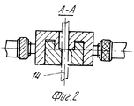
Сущность изобретения поясняется чертежами, на которых показаны: фиг. 1. Ручные ножницы для резки проволоки и прутков, общий вид; фиг. 2. То же. Разрез А-А на фиг. 1. The invention is illustrated by drawings, which show: FIG. 1. Manual shears for cutting wire and rods, general view; FIG. 2. The same. Section AA in FIG. 1.
Ручные ножницы для резки проволоки и прутков содержат два поворотных вокруг общей оси рычага 1 и 2, на которых закреплены ножи типа втулок - наружный втулочный нож 3 и второй нож 4 со сквозными пазами 5, по поверхности которых проходит ось поворота рычагов. Рычаг 1 установлен с возможностью перемещения в направляющем пазу 6 наружного втулочного ножа 3 и закреплен при помощи штифта 7 в теле второго ножа 4. Оба рычага выполнены составными в виде телескопических деталей для обеспечения компактности и портативности и включают в себя рукоятку 8, контргайку 9, при этом непрерывная резьба рычагов в местах размещения рукояток 8 разделена на две части 10 и 11 ступенью с гладким обнижением по диаметру 12, а непрерывная резьба рукояток 8 разделена соответствующей цилиндрической расточкой 13, большей наружного диаметра резьбы. Необходимо отметить, что резьба рычагов 1 и 2 в местах размещения рукояток 8 должна быть сначала нарезана на всю длину а затем разделена на части 10 и 11 обнижением 12 по диаметру, т.е. непрерывная резьба условно прерывается. В противном случае рукоятку 8 невозможно навернуть на рычаг 2. То же касается и рукояток 8. Резьбу в рукоятке 8 необходимо нарезать с одной установки на всю длину, т.е. обеспечить условную непрерывность резьбы обеих частей рукоятки. На фиг.1 и фиг.2 условно показан пруток 14 перед разрезкой. Manual scissors for cutting wire and rods contain two levers 1 and 2 that are rotatable around a common axis, on which blades of a sleeve type are fixed - an outer sleeve knife 3 and a second knife 4 with through grooves 5, on the surface of which the axis of rotation of the levers passes. The lever 1 is mounted to move in the guide groove 6 of the outer sleeve knife 3 and secured with a pin 7 in the body of the second knife 4. Both levers are made integral in the form of telescopic parts for compactness and portability and include a handle 8, a lock nut 9, this continuous thread of the levers in the places of placement of the arms 8 is divided into two parts 10 and 11 step with a smooth decrease in diameter 12, and a continuous thread of the arms 8 is divided by the corresponding cylindrical bore 13, larger than the outer thread diameter. It should be noted that the thread of the levers 1 and 2 in the places of placement of the arms 8 must first be cut into full length and then divided into parts 10 and 11 by a reduction of 12 in diameter, i.e. continuous thread conditionally interrupted. Otherwise, the handle 8 cannot be screwed onto the lever 2. The same applies to the handles 8. The threads in the handle 8 must be cut from one installation to the entire length, i.e. provide conditional continuity of the thread of both parts of the handle. In Fig.1 and Fig.2 conventionally shows the
Работа ножниц осуществляется следующим образом. The work of scissors is as follows.
Предварительно рычаг 2 заворачивается в наружный кольцевой нож 3, при этом контр-гайка 9 фиксирует рукоятку 8, упираясь в ее торец. Рычаг 1, фиксируемый штифтом 7, не разбирается. Previously, the lever 2 is wrapped in an outer ring knife 3, while the counter-nut 9 fixes the handle 8, resting against its end. The lever 1, fixed by the pin 7, is not disassembled.
Как показано на фиг. 1 и 2, пруток 14 устанавливается в пазу 5, после чего рычаги 1 и 2 разворачиваются вручную навстречу друг другу, в результате чего пруток 14 перерезается. Рычаг 1, запрессованный в нож 4 и зафиксированный штифтом 7, обеспечивает не только рабочий ход кольцевых ножей, но и служит одновременно благодаря пазу 6 ограничителем поворота рычагов. As shown in FIG. 1 and 2, the
Если условие резания недостаточно, то производят удлинение рычагов. Для этого контр-гайка 9 ослабляется, в рукоятка 8 свинчивается с резьбовых частей 10 и 11 и, после перемещения по гладкому обнижению 12, наворачивается на резьбе 11 на конце рычага 2. Контр-гайка 9 также переставляется в крайнее положение и фиксирует рукоятку 8. Благодаря обнижению 12 и расточке 13 время перестановки рукоятки 8 на рычаге 2 значительно сокращается, поскольку свинчивание рукоятки 8 и гайки 9 не производится по всей длине рычага 2 и используется телескопическое соединение. If the cutting condition is not enough, then leverage is lengthened. To do this, the counter nut 9 is loosened, screwed into the handle 8 from the threaded parts 10 and 11 and, after moving along a smooth lowering 12, is screwed onto the thread 11 at the end of the lever 2. The counter nut 9 is also rearranged and fixes the handle 8. Due to the lowering of 12 and the bore 13, the shift time of the handle 8 on the lever 2 is significantly reduced, since the screwing of the handle 8 and the nut 9 is not performed along the entire length of the lever 2 and a telescopic connection is used.
Таким образом, применение предлагаемых ручных ножниц обеспечивает улучшение условий резания за счет того, что рычаги расположены в плоскости резания, возможность увеличения усилия резания приблизительно в 2 раза за счет изменения длины рычагов, упрощение конструкции втулочных ножей компактность и портативность инструмента, поскольку рычаги выполнены составными в виде телескопических, скрепленных резьбовым соединением деталей. Thus, the use of the proposed manual scissors provides improved cutting conditions due to the fact that the levers are located in the cutting plane, the possibility of increasing the cutting force by approximately 2 times due to a change in the length of the levers, simplifying the design of the sleeve knives, the compactness and portability of the tool, since the levers are made integral in in the form of telescopic parts fastened by a threaded connection.
Claims (1)
Priority Applications (1)
| Application Number | Priority Date | Filing Date | Title |
|---|---|---|---|
| SU5062278 RU2064373C1 (en) | 1992-09-28 | 1992-09-28 | Hand shears to cut wire and bars |
Applications Claiming Priority (1)
| Application Number | Priority Date | Filing Date | Title |
|---|---|---|---|
| SU5062278 RU2064373C1 (en) | 1992-09-28 | 1992-09-28 | Hand shears to cut wire and bars |
Publications (1)
| Publication Number | Publication Date |
|---|---|
| RU2064373C1 true RU2064373C1 (en) | 1996-07-27 |
Family
ID=21613340
Family Applications (1)
| Application Number | Title | Priority Date | Filing Date |
|---|---|---|---|
| SU5062278 RU2064373C1 (en) | 1992-09-28 | 1992-09-28 | Hand shears to cut wire and bars |
Country Status (1)
| Country | Link |
|---|---|
| RU (1) | RU2064373C1 (en) |
Cited By (3)
| Publication number | Priority date | Publication date | Assignee | Title |
|---|---|---|---|---|
| RU2164195C2 (en) * | 1998-12-15 | 2001-03-20 | Комсомольское-на-Амуре авиационное производственное объединение | Apparatus for separating round cross section blanks |
| RU2266193C2 (en) * | 2003-09-23 | 2005-12-20 | Якимов Иван Тимофеевич | Manual cutting pliers |
| RU2305613C1 (en) * | 2005-12-28 | 2007-09-10 | Николай Владимирович Мастыко | Cutting pliers |
-
1992
- 1992-09-28 RU SU5062278 patent/RU2064373C1/en active
Non-Patent Citations (1)
| Title |
|---|
| Авторское свидетельство СССР N1511021, кл. B 21 D 29/02, опублик. 1989. Авторское свидетельство СССР № 559784, кл. B 21 D 29/02, опублик. 1977. * |
Cited By (3)
| Publication number | Priority date | Publication date | Assignee | Title |
|---|---|---|---|---|
| RU2164195C2 (en) * | 1998-12-15 | 2001-03-20 | Комсомольское-на-Амуре авиационное производственное объединение | Apparatus for separating round cross section blanks |
| RU2266193C2 (en) * | 2003-09-23 | 2005-12-20 | Якимов Иван Тимофеевич | Manual cutting pliers |
| RU2305613C1 (en) * | 2005-12-28 | 2007-09-10 | Николай Владимирович Мастыко | Cutting pliers |
Similar Documents
| Publication | Publication Date | Title |
|---|---|---|
| EP0611632B1 (en) | Two-handed guided electrical hand tool with grab handle | |
| US5400511A (en) | Thumbpiece for modular power-driven knife | |
| US4055891A (en) | Ratchet-operated cable cutter | |
| EP0569382B1 (en) | Hand tool | |
| US7458882B2 (en) | Adjustable handheld tool | |
| DE4022668A1 (en) | ELECTRIC HAND TOOL, IN PARTICULAR ANGLE GRINDING MACHINE | |
| US4972583A (en) | Tool for stripping cables | |
| EP0569370A1 (en) | Hand-held power tool. | |
| KR980000725A (en) | Round bar blades for gear cutting and finishing and combined cutter heads | |
| RU2064373C1 (en) | Hand shears to cut wire and bars | |
| US3181239A (en) | Tree and shrub branch saw | |
| US6216350B1 (en) | Coping saw with multi-directional cutting blade with two cutting surfaces | |
| US2781578A (en) | Motor driven hand carving knife | |
| KR0156733B1 (en) | Ratchet wrench with an angularly adjustable handle | |
| US3453731A (en) | Handtools | |
| US3025597A (en) | Cable sheath cutter | |
| US2679270A (en) | Support for screw-removing tools | |
| US3221962A (en) | Apparatus for cutting pipe | |
| EP0569360A1 (en) | Hand-held power tool | |
| DE3304206C2 (en) | ||
| US2362112A (en) | Wire tightening tool | |
| US2761212A (en) | Driving connection for a cutter blade | |
| US2595033A (en) | Pinking shears | |
| CN117477447A (en) | Cable opening tool | |
| US4399721A (en) | Wrench |