RU2063627C1 - Device for determining physical properties of liquids and gases - Google Patents
Device for determining physical properties of liquids and gases Download PDFInfo
- Publication number
- RU2063627C1 RU2063627C1 SU925058556A SU5058556A RU2063627C1 RU 2063627 C1 RU2063627 C1 RU 2063627C1 SU 925058556 A SU925058556 A SU 925058556A SU 5058556 A SU5058556 A SU 5058556A RU 2063627 C1 RU2063627 C1 RU 2063627C1
- Authority
- RU
- Russia
- Prior art keywords
- piston
- liner
- paragraphs
- chamber
- constant
- Prior art date
Links
Images
Classifications
-
- G—PHYSICS
- G01—MEASURING; TESTING
- G01N—INVESTIGATING OR ANALYSING MATERIALS BY DETERMINING THEIR CHEMICAL OR PHYSICAL PROPERTIES
- G01N29/00—Investigating or analysing materials by the use of ultrasonic, sonic or infrasonic waves; Visualisation of the interior of objects by transmitting ultrasonic or sonic waves through the object
- G01N29/02—Analysing fluids
-
- G—PHYSICS
- G01—MEASURING; TESTING
- G01N—INVESTIGATING OR ANALYSING MATERIALS BY DETERMINING THEIR CHEMICAL OR PHYSICAL PROPERTIES
- G01N29/00—Investigating or analysing materials by the use of ultrasonic, sonic or infrasonic waves; Visualisation of the interior of objects by transmitting ultrasonic or sonic waves through the object
- G01N29/22—Details, e.g. general constructional or apparatus details
- G01N29/222—Constructional or flow details for analysing fluids
-
- G—PHYSICS
- G01—MEASURING; TESTING
- G01N—INVESTIGATING OR ANALYSING MATERIALS BY DETERMINING THEIR CHEMICAL OR PHYSICAL PROPERTIES
- G01N2291/00—Indexing codes associated with group G01N29/00
- G01N2291/02—Indexing codes associated with the analysed material
- G01N2291/028—Material parameters
- G01N2291/02818—Density, viscosity
Landscapes
- Physics & Mathematics (AREA)
- Acoustics & Sound (AREA)
- Health & Medical Sciences (AREA)
- Life Sciences & Earth Sciences (AREA)
- Chemical & Material Sciences (AREA)
- Analytical Chemistry (AREA)
- Biochemistry (AREA)
- General Health & Medical Sciences (AREA)
- General Physics & Mathematics (AREA)
- Immunology (AREA)
- Pathology (AREA)
- Investigating Or Analyzing Materials By The Use Of Ultrasonic Waves (AREA)
- Investigating Or Analysing Materials By Optical Means (AREA)
- Investigating Or Analyzing Materials Using Thermal Means (AREA)
- Investigating Or Analyzing Non-Biological Materials By The Use Of Chemical Means (AREA)
- Sampling And Sample Adjustment (AREA)
Abstract
Description
Изобретение относится к приборостроению и может быть использовано для прецизионных измерений физических свойств флюидов при высоких давлениях в нефтяной, газовой, машиностроительной промышленностях, медицине, биологии и т.д. The invention relates to instrumentation and can be used for precision measurements of the physical properties of fluids at high pressures in the oil, gas, engineering industries, medicine, biology, etc.
Известно устройство высокого давления [1] содержащее акустическую камеру с переменной базой и пресс с поршнем, объединенные одним гидравлическим узлом. Соединение поршня с индикатором перемещений позволяет определить расстояние, на которое перемещается поршень, изменение объема исследуемой жидкости под давлением, ее плотности и изотермической сжимаемости. A high pressure device [1] is known comprising an acoustic chamber with a variable base and a press with a piston, united by one hydraulic unit. The connection of the piston with the displacement indicator allows you to determine the distance over which the piston moves, the change in the volume of the test fluid under pressure, its density and isothermal compressibility.
Недостатком устройства является низкая точность определения указанных характеристик. The disadvantage of this device is the low accuracy of determining these characteristics.
Наиболее близким к предлагаемому (прототипом) является ультразвуковое устройство для контроля параметров жидкостей [2] Устройство состоит из камеры высокого давления с поршнем и ультразвуковых пьезопреобразователей, размещенных снаружи корпуса, блока нагружения, измерителя перемещений, электронного блока возбуждения импульсных сигналов, их приема, обработки и регистрации данных. Closest to the proposed (prototype) is an ultrasonic device for monitoring the parameters of liquids [2] The device consists of a high-pressure chamber with a piston and ultrasonic piezoelectric transducers placed outside the housing, a loading unit, a displacement meter, an electronic unit for exciting pulse signals, receiving, processing and data logging.
Недостатками устройства является низкая точность определения акустических параметров, плотности и сжимаемости. The disadvantages of the device is the low accuracy of determining acoustic parameters, density and compressibility.
Существенным недостатком перечисленных устройств является их низкая точность определения коэффициента изотермической сжимаемости. Это резко снижает эффективность акустических методов и не позволяет надежно их использовать для определения теплофизических свойств флюидов, таких как изобарная СP и изохорная С теплоемкости, т. к. отношение CP/CV= βT/βS, где βT коэффициент изотермической сжимаемости, βS= 1/ρc2 коэффициент адиабатической сжимаемости, ρ плотность, c скорость звука. При высокой точности определения скорости ультразвука точность определения коэффициента сжимаемости и теплоемкостей, определяется точностью определения плотности и объема и их измерений от давления температуры.A significant drawback of these devices is their low accuracy in determining the coefficient of isothermal compressibility. This sharply reduces the effectiveness of acoustic methods and does not allow them to be reliably used to determine the thermophysical properties of fluids, such as isobaric С P and isochoric С heat capacities, because the ratio C P / C V = β T / β S , where β T is the isothermal coefficient compressibility, β S = 1 / ρc 2 adiabatic compressibility coefficient, ρ density, c speed of sound. With high accuracy in determining the speed of ultrasound, the accuracy in determining the coefficient of compressibility and heat capacity is determined by the accuracy in determining the density and volume and their measurements from temperature pressure.
Задача, на решение которой направлено изобретение повышение точности и разрешающей способности измерений физических свойств флюидов при различных P, V, T (P давление, V объем, Т температура). The problem the invention is aimed at improving the accuracy and resolution of measurements of the physical properties of fluids at various P, V, T (P pressure, V volume, T temperature).
Поставленная задача решена тем, что в устройстве, содержащем камеру с флюидом, поршень, корпус, термостат, преобразователь колебаний, блок возбуждения и приема сигналов, регистрации и обработки данных, - преобразователь колебаний размещен внутри камеры параллельно торцевой поверхности поршня таким образом, что образует две измерительные ячейки с постоянной и переменной акустическими базами. The problem is solved in that in a device containing a chamber with a fluid, a piston, a housing, a thermostat, an oscillation transducer, an excitation and signal receiving, data recording and processing unit, the oscillation transducer is placed inside the chamber parallel to the end surface of the piston in such a way that it forms two measuring cells with constant and variable acoustic bases.
Во всех случаях использования изобретения названной совокупности существенных признаков достаточно, т. к. излучение пьезокристалла в ячейку с постоянной акустической базой позволяет определять скорость и поглощение звука, а в ячейку с переменной базой перемещение поршня. Расстояние, на которое перемещают поршень, определяют или по времени прохождения сигнала, или по длине волны и частоте, и/или считая число полуволн, укладывающихся в расстояние от кристалла до отражающей поверхности поршня. Такое расположение преобразователя колебаний позволяет с помощью поршня совместить функцию создания давления с прецизионным измерением, перемещения, изменения объема, плотности, изотермической сжимаемости, скорости и поглощения ультразвука, определения изобарной и изохорной теплоемкостей, коэффициента теплового расширения и др. теплофизических свойств, термодинамических функций и потенциалов и т. д. Кроме того, с помощью поршня компенсируют изменение объема в различных РVТ-условиях. In all cases of using the invention, the above-mentioned set of essential features is sufficient, since the radiation of a piezocrystal into a cell with a constant acoustic base allows you to determine the speed and absorption of sound, and the piston moves into a cell with a variable base. The distance over which the piston is moved is determined either by the signal propagation time, or by the wavelength and frequency, and / or by counting the number of half-waves falling within the distance from the crystal to the reflecting surface of the piston. This arrangement of the vibration transducer allows you to use the piston to combine the function of creating pressure with precision measurement, displacement, volume, density, isothermal compressibility, ultrasound velocity and absorption, determination of isobaric and isochoric heat capacities, thermal expansion coefficient, and other thermophysical properties, thermodynamic functions and potentials etc. In addition, with the help of a piston, they compensate for the change in volume under various РVТ-conditions.
Использование одновременно с ячейкой постоянной базы, ячейки переменной базы, позволяет также существенно расширить возможности устройства при измерениях коэффициента затухания звука. Возбуждение при этом непрерывных колебаний и проведение измерений в резонаторном режиме позволяет определять перемещение, а отсюда и изотермическую сжимаемость, по измерениям частоты колебаний, т. е. с большой точностью. The use of a constant base cell, a variable base cell simultaneously with the cell, also allows you to significantly expand the capabilities of the device when measuring the sound attenuation coefficient. The excitation of continuous oscillations and carrying out measurements in the resonator mode makes it possible to determine the displacement, and hence the isothermal compressibility, from measurements of the oscillation frequency, i.e., with great accuracy.
Выполнение измерительной камеры объемом, много большим величины его изменения, ведет к повышению стабильности показаний и точности определения величин, связанных с изменением объема плотности, сжимаемости, коэффициента теплового расширения и т. д. Это следует из того, что точность их определения обусловлена также отношением объемов ячеек с переменной и постоянной базами, отношением Dv/v, точностью измерения объема, где V объем, ΔvV - величина изменения объема. Это позволяет также использовать устройство и по другим назначениям, например как прецизионный измеритель температуры. The implementation of the measuring chamber with a volume much larger than the value of its change leads to an increase in the stability of readings and the accuracy of determining the values associated with changes in the density, compressibility, coefficient of thermal expansion, etc. This follows from the fact that the accuracy of their determination is also due to the ratio of volumes cells with variable and constant bases, Dv / v ratio, volume measurement accuracy, where V is the volume, ΔvV is the value of the volume change. This also allows the device to be used for other purposes, for example, as a precision temperature meter.
Однако объем камеры целесообразно назначать, исходя из его оптимального значения, определяемого требуемой точностью измеряемых величин. Чрезмерное увеличение объема усложняет системы создания и поддержания давления, увеличивает его габариты и металлоемкость. However, it is advisable to assign the volume of the chamber based on its optimal value, determined by the required accuracy of the measured values. Excessive increase in volume complicates the system of creating and maintaining pressure, increases its dimensions and metal consumption.
Выполнение ячеек сообщающимися позволяет иметь в них идентичные условия, упрощает устройство и повышает его надежность. The implementation of the communicating cells allows them to have identical conditions, simplifies the device and increases its reliability.
Выполнение поршня с большим диаметром, чем диаметр излучающей в сторону поршня поверхности преобразователя колебаний, позволяет уменьшить дифракционные искажения сигнала. The execution of the piston with a larger diameter than the diameter of the surface of the oscillation transducer radiating towards the piston, allows to reduce the diffraction distortion of the signal.
Размещение по скользящей посадке в канале между поршнем и преобразователем колебаний поршневого вкладыша повышает надежность герметизации устройства за счет притертости поверхностей вкладыша и канала и возможности дополнительно уплотнить поршень, т. к. роль отражателя выполняет вкладыш и посадочные требования к поршню существенно упрощаются. Placing along a sliding fit in the channel between the piston and the oscillation transducer of the piston liner increases the reliability of sealing the device due to the grinding of the surfaces of the liner and the channel and the ability to additionally seal the piston, since the role of the reflector is played by the liner and the piston landing requirements are greatly simplified.
Это расширяет и возможности устройства при исследованиях в более широком диапазоне изменений давления и температуры. Указанное размещение вкладыша одновременно повышает точность измерений, т. к. гарантирует параллельность отражающей поверхности вкладыша и излучающей поверхности преобразователя колебаний. Этого трудно добиться с помощью отражающей поверхности уплотненного поршня, поскольку она будет неизбежно отклоняться от требуемого положения из-за влияния уплотнений (или сальников). This extends the capabilities of the device during research in a wider range of changes in pressure and temperature. The indicated placement of the liner at the same time increases the accuracy of the measurements, because it guarantees parallelism between the reflecting surface of the liner and the radiating surface of the oscillation transducer. This is difficult to achieve with the reflective surface of the sealed piston, since it will inevitably deviate from the desired position due to the influence of the seals (or glands).
Выполнение противоположного торца поршневого вкладыша вогнутым внутрь тела вкладыша дополнительно герметизирует измерительную камеру при увеличении давления и практически полностью исключает возможность влияния других, кроме основной, отраженных волн. The execution of the opposite end of the piston liner concave into the body of the liner additionally seals the measuring chamber with increasing pressure and almost completely eliminates the possibility of influence of other than the main reflected waves.
Заполнение пространства между поршнем и вкладышем флюидом с большим модулей упругости, чем исследуемый флюид, позволяет более эффективно осуществлять передачу давления в измерительную камеру с помощью основного поршня. Выбор флюидов несмешивающимися уменьшает вероятность проникновения их в зазор между вкладышем и поверхностью корпуса. Filling the space between the piston and the liner with a fluid with greater elastic moduli than the fluid under study allows more efficient transfer of pressure to the measuring chamber using the main piston. The choice of immiscible fluids reduces the likelihood of their penetration into the gap between the liner and the housing surface.
Выполнение корпуса устройства или его элемента таким образом, что он образует с поршнем плунжерную пару, повышает точность измерений и надежность устройства, уплотнение поршня также служит этой цели и одновременно расширяет диапазон достигаемых давлений. The execution of the housing of the device or its element in such a way that it forms a plunger pair with the piston increases the measurement accuracy and reliability of the device, the piston seal also serves this purpose and at the same time extends the range of achievable pressures.
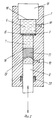
На фиг. 1 изображена принципиальная конструкция устройства; на фиг. 2 - конструкция устройства с поршневым вкладышем. In FIG. 1 shows the basic design of the device; in FIG. 2 - design of the device with a piston liner.
Устройство содержит корпус 1, представляющий собой сосуд высокого давления, в котором на держателе 2 с отверстиями 3 с помощью крепежного элемента 4 установлен преобразователь колебаний 5 (в данном примере - пьезокристалл ниобата лития среза У-З6) таким образом, что образует две измерительные ячейки с постоянной 6 и переменной 7 акустическими базами. Для создания давления в измерительных ячейках служит поршень 8 с отражающей ультразвуковые волны поверхностью 9, выполненный с элементом корпуса 1, в котором он движется как плунжерная пара. Через отверстие 10 камеру для измерений заполняют флюидом. Камера снабжена датчиками давления 11 (например, манганиновым манометром) и температуры 12 (например, термопарой), соединенными через электровводы высокого давления (не показаны), выполненными в крышке 13, с электронным блоком возбуждения и приема сигналов, регистрации и обработки данных 14. С блоком 14 также через электровводы высокого давления соединены электроды, напыленные на поверхности пьезокристалла 5 (не показаны), на крышке 13 выполнена отражающая поверхность 15, параллельная излучающей поверхности пьезокристалла 5. The device comprises a
Измерительные ячейки 6 и 7 могут заполнять как одним и тем же, подлежащим исследованию флюидом, так и исследуемым, например, эталонным флюидом. При этом давление из ячейки 7 передается в ячейку 6, например, через упругий элемент (не показан), перекрывающий отверстия 3 и разделяющий флюиды. В этом случае нет необходимости устанавливать датчики 11 и 12, т. к. ячейка 6 может использоваться как измеритель давления или температуры. The
Для проведения измерений при изменении температуры и в различных термодинамических условиях устройство помещают в термостатирующую рубашку (не показана). To take measurements when the temperature changes and in various thermodynamic conditions, the device is placed in a thermostatic jacket (not shown).
На фиг.2 показан еще один вариант исполнения устройства, где пьезокристалл 5 разделяет камеру для измерений на ячейку 6 с постоянной акустической базой и ячейку 7 с переменной базой, для сообщаемости ячеек в кристалле выполнены отверстия 16. Между поршнем 8 и пьезокристаллом 5 размещен поршневой вкладыш 17 с отражающей поверхностью 18 и вогнутой внутрь вкладыша поверхностью 19 для лучшей герметизации и расширения диапазона давлений служит уплотнение 20. Figure 2 shows another embodiment of the device, where the
Устройство можно выполнять также с дополнительно установленными преобразователями колебаний (не показаны) вместо отражающих поверхностей 15 на крышке 13 и/или 9 на поршне 8. Такое размещение преобразователей несколько усложняет конструкцию, но в то же время расширяет возможности устройства, позволяет использовать различные измерительные схемы, облегчает задачу выделения сигнала, прошедшего через флюид. Аналогично прототипу, дополнительные преобразователи могут быть вынесены за пределы корпуса. При этом размеры крышки и поршня рассчитывают как акустические задержки или выполняют в них звуководы акустические задержки. The device can also be performed with additionally installed oscillation transducers (not shown) instead of reflective surfaces 15 on the
Измерения проводят следующим образом. The measurements are carried out as follows.
Известными методами определяют объем устройства, подлежащий заполнению исследуемым флюидом. Через отверстие 10 вакуумируют камеру для измерений. Термостатируют устройство и бюретку (не показана) с подлежащим исследованию флюидом, в данном примере газовый конденсат, при комнатной температуре (или требуемой температуре). Known methods determine the volume of the device to be filled with the test fluid. Through the
При этой же температуре известными методами определяют плотность конденсата, например, методом гидростатического взвешивания. Затем заполняют ячейки 6, 7 газовым конденсатом, закрывают отверстие 10 заглушкой (не показана) с помощью термостата достигают температуры, при которой нужно провести измерения, и поддерживают ее. Подают на пьезокристалл 5 синусоидальный сигнал. В ячейке с постоянной базой проводят измерения резонансной частоты, добротности, скорости и поглощения ультразвука, известными для интерферометра с постоянной базой, методами. Перемещая поршень, повышают давление с обеих ячейках и проводят измерения акустических характеристик в зависимости от давления при постоянной температуре. По изменению чистоты колебаний при движении поршня определяют величину его перемещения и изменение объема и плотности, а с помощью датчика 11 измеряют давление в ячейках. At the same temperature, the density of the condensate is determined by known methods, for example, by hydrostatic weighing. Then the
Коэффициент изотермической сжимаемости определяют из выражения
![]()
где V объем;
Т температура;
Р давление;
fрез резонансная частота;
K коэффициент пропорциональности.The coefficient of isothermal compressibility is determined from the expression
![]()
where is V volume;
T temperature;
P pressure;
f res resonant frequency;
K is the coefficient of proportionality.
Плотность можно определить из выражения:
![]()
где ρo плотность и объем при атмосферном давлении, соответственно;
ρp плотность и объем при давлении P.Density can be determined from the expression:
![]()
where ρ o density and volume at atmospheric pressure, respectively;
ρ p density and volume at pressure P.
Зная наряду с традиционными акустическими параметрами изотермическую сжимаемость и плотность, известными методами рассчитывают комплекс термодинамических, теплофизических молекулярно-кинетических и физико-химических свойств, функций и потенциалов и т. д. Knowing, along with traditional acoustic parameters, isothermal compressibility and density, the complex of thermodynamic, thermophysical molecular kinetic and physicochemical properties, functions and potentials, etc., is calculated by known methods.
Таким образом, устройство позволяет не только определять с высокой точностью традиционные акустические параметры, но и теплофизические свойства, до сих пор определяемые, в основном, калориметическими методами, а также плотность и изотермическую сжимаемость, существенно расширить возможности акустических методов. Кроме того, физические принципы, заложенные в устройстве, позволяют аналогичную конструкцию в подобных целях использовать и с другими типами источников (преобразователей) колебаний, например электромагнитных СВЧ-колебаний. Thus, the device allows not only to determine traditional acoustic parameters with high accuracy, but also thermophysical properties, still determined mainly by calorimetric methods, as well as density and isothermal compressibility, to significantly expand the capabilities of acoustic methods. In addition, the physical principles embodied in the device allow a similar design for similar purposes to be used with other types of sources (transducers) of oscillations, such as electromagnetic microwave oscillations.
Claims (9)
Priority Applications (11)
| Application Number | Priority Date | Filing Date | Title |
|---|---|---|---|
| SU925058556A RU2063627C1 (en) | 1992-08-13 | 1992-08-13 | Device for determining physical properties of liquids and gases |
| EP93919739A EP0607458B1 (en) | 1992-08-13 | 1993-08-12 | Device for determining physical properties of fluids |
| US08/211,684 US5509299A (en) | 1992-08-13 | 1993-08-12 | Apparatus for determining physical properties of fluids |
| PCT/RU1993/000200 WO1994004914A1 (en) | 1992-08-13 | 1993-08-12 | Device for determining physical properties of fluids |
| CA002121260A CA2121260A1 (en) | 1992-08-13 | 1993-08-12 | Apparatus for determining physical properties of fluids |
| JP6506144A JPH07500424A (en) | 1992-08-13 | 1993-08-12 | Device for measuring physical properties of fluids |
| AT93919739T ATE160447T1 (en) | 1992-08-13 | 1993-08-12 | METHOD FOR DETERMINING PHYSICAL PROPERTIES OF LIQUIDS |
| AU49875/93A AU667408B2 (en) | 1992-08-13 | 1993-08-12 | Apparatus for determining physical properties of fluids |
| HU9401037A HUT71144A (en) | 1992-08-13 | 1993-08-12 | Device for determining physical properties of fluids |
| CZ94862A CZ86294A3 (en) | 1992-08-13 | 1993-08-12 | Apparatus for determining physical properties of liquids |
| DE69315320T DE69315320T2 (en) | 1992-08-13 | 1993-08-12 | METHOD FOR DETERMINING PHYSICAL PROPERTIES OF LIQUIDS |
Applications Claiming Priority (1)
| Application Number | Priority Date | Filing Date | Title |
|---|---|---|---|
| SU925058556A RU2063627C1 (en) | 1992-08-13 | 1992-08-13 | Device for determining physical properties of liquids and gases |
Publications (1)
| Publication Number | Publication Date |
|---|---|
| RU2063627C1 true RU2063627C1 (en) | 1996-07-10 |
Family
ID=21611521
Family Applications (1)
| Application Number | Title | Priority Date | Filing Date |
|---|---|---|---|
| SU925058556A RU2063627C1 (en) | 1992-08-13 | 1992-08-13 | Device for determining physical properties of liquids and gases |
Country Status (11)
| Country | Link |
|---|---|
| US (1) | US5509299A (en) |
| EP (1) | EP0607458B1 (en) |
| JP (1) | JPH07500424A (en) |
| AT (1) | ATE160447T1 (en) |
| AU (1) | AU667408B2 (en) |
| CA (1) | CA2121260A1 (en) |
| CZ (1) | CZ86294A3 (en) |
| DE (1) | DE69315320T2 (en) |
| HU (1) | HUT71144A (en) |
| RU (1) | RU2063627C1 (en) |
| WO (1) | WO1994004914A1 (en) |
Families Citing this family (8)
| Publication number | Priority date | Publication date | Assignee | Title |
|---|---|---|---|---|
| DE4423822C1 (en) * | 1994-07-06 | 1996-01-04 | Karlsruhe Forschzent | Sensor for contactless measurement of media parameters |
| US20030101819A1 (en) * | 2001-12-04 | 2003-06-05 | Mutz Mitchell W. | Acoustic assessment of fluids in a plurality of reservoirs |
| US7454958B2 (en) * | 2001-12-04 | 2008-11-25 | Labcyte Inc. | Acoustic determination of properties of reservoirs and of fluids contained therein |
| US6640625B1 (en) * | 2002-05-08 | 2003-11-04 | Anthony R. H. Goodwin | Method and apparatus for measuring fluid density downhole |
| EP1517140A3 (en) * | 2003-03-19 | 2005-04-06 | TF Instruments GmbH | Method and device for diagnostic investigation of biological samples |
| AU2010355265B2 (en) * | 2010-06-17 | 2014-04-10 | Halliburton Energy Services, Inc. | Non-invasive compressibility and in situ density testing of a fluid sample in a sealed chamber |
| CN107941842A (en) * | 2017-12-13 | 2018-04-20 | 湖南工业大学 | A kind of high molecular material volume, angle and dissipative, slack time test device and method |
| DE102021132835A1 (en) * | 2021-12-13 | 2023-06-15 | Truedyne Sensors AG | measuring device |
Family Cites Families (12)
| Publication number | Priority date | Publication date | Assignee | Title |
|---|---|---|---|---|
| US2711646A (en) * | 1950-04-25 | 1955-06-28 | Jean S Mendousse | Acoustic impedance measuring device for liquids |
| US2833142A (en) * | 1955-02-15 | 1958-05-06 | Ernest M Runquist | Ultrasonic, high pressure interferometer |
| LU71228A1 (en) * | 1974-10-31 | 1976-03-17 | ||
| US4249422A (en) * | 1979-10-22 | 1981-02-10 | The United States Of America As Represented By The Secretary Of The Navy | Apparatus and process for determining the composition of fluid-filled cavities |
| US4773267A (en) * | 1980-03-31 | 1988-09-27 | Micro Pure Systems, Inc. | Ultrasonic sensing |
| US4325255A (en) * | 1980-04-07 | 1982-04-20 | Energy And Minerals Research Co. | Ultrasonic apparatus and method for measuring the characteristics of materials |
| US4324131A (en) * | 1980-04-09 | 1982-04-13 | Allan Rosencwaig | Liquid chromatography detector |
| SU1226279A1 (en) * | 1984-09-20 | 1986-04-23 | Всесоюзный заочный машиностроительный институт | Ultrasonic device for testing liquid parameters |
| SE8700662D0 (en) * | 1987-02-18 | 1987-02-18 | Metator Kb | SET AND DEVICE FOR VOLUME SAFETY AND DEVICE FOR DETERMINING A PI DEPENDENT VALUE |
| US4936143A (en) * | 1989-04-28 | 1990-06-26 | Eaton Corporation | Cylinders having piston position measurement |
| US4969362A (en) * | 1989-06-19 | 1990-11-13 | Nusonics, Inc. | Dual element transducer |
| FR2649206B1 (en) * | 1989-07-03 | 1993-02-05 | Total Petroles | METHOD AND DEVICE FOR MEASURING THE GELIFICATION OF PARAFFINIC OIL PRODUCTS, ESPECIALLY CRUDE |
-
1992
- 1992-08-13 RU SU925058556A patent/RU2063627C1/en active
-
1993
- 1993-08-12 CZ CZ94862A patent/CZ86294A3/en unknown
- 1993-08-12 AU AU49875/93A patent/AU667408B2/en not_active Ceased
- 1993-08-12 HU HU9401037A patent/HUT71144A/en unknown
- 1993-08-12 DE DE69315320T patent/DE69315320T2/en not_active Expired - Fee Related
- 1993-08-12 AT AT93919739T patent/ATE160447T1/en not_active IP Right Cessation
- 1993-08-12 JP JP6506144A patent/JPH07500424A/en active Pending
- 1993-08-12 US US08/211,684 patent/US5509299A/en not_active Expired - Fee Related
- 1993-08-12 CA CA002121260A patent/CA2121260A1/en not_active Abandoned
- 1993-08-12 WO PCT/RU1993/000200 patent/WO1994004914A1/en not_active Application Discontinuation
- 1993-08-12 EP EP93919739A patent/EP0607458B1/en not_active Expired - Lifetime
Non-Patent Citations (1)
| Title |
|---|
| Ultrasonics, 1991, vol. 29, March, р. 108. Авторское свидетельство СССР N 1226279, кл. G 01 N 29/00, 1986. * |
Also Published As
| Publication number | Publication date |
|---|---|
| EP0607458A1 (en) | 1994-07-27 |
| US5509299A (en) | 1996-04-23 |
| JPH07500424A (en) | 1995-01-12 |
| EP0607458B1 (en) | 1997-11-19 |
| HUT71144A (en) | 1995-11-28 |
| DE69315320T2 (en) | 1998-06-10 |
| EP0607458A4 (en) | 1994-08-31 |
| ATE160447T1 (en) | 1997-12-15 |
| AU4987593A (en) | 1994-03-15 |
| HU9401037D0 (en) | 1994-08-29 |
| DE69315320D1 (en) | 1998-01-02 |
| WO1994004914A1 (en) | 1994-03-03 |
| CA2121260A1 (en) | 1994-03-03 |
| AU667408B2 (en) | 1996-03-21 |
| CZ86294A3 (en) | 1994-08-17 |
Similar Documents
| Publication | Publication Date | Title |
|---|---|---|
| US10352907B2 (en) | High-temperature, high pressure acoustic resonance cell | |
| RU2063627C1 (en) | Device for determining physical properties of liquids and gases | |
| Chivers et al. | Effective area to be used in diffraction corrections | |
| US4154099A (en) | Process and device for measuring the ratio of the specific heats of a fluid at a constant pressure and a constant volume | |
| US5542298A (en) | Method for determining physical stage parameters of a medium and an apparatus for carrying out same | |
| US3357245A (en) | System for volumetric analysis | |
| CN1107231A (en) | Device for measuring physical property of fluid | |
| O’Hara | Influence of pressure, temperature, and pore fluid on the frequency-dependent attenuation of elastic waves in Berea sandstone | |
| Elder | [2] Density measurements by the mechanical oscillator | |
| JP2744977B2 (en) | Simultaneous measurement method of pressure-volume-temperature characteristics in materials | |
| RU2052804C1 (en) | Method for determination on isothermic compressibility factor | |
| Roach et al. | Thermal expansion, velocity of sound, and compressibility in liquid 3 He under pressure | |
| Spetzler et al. | Precise length measurement technique under hydrostatic pressure: Isothermal bulk modulus of PMMA | |
| RU2112220C1 (en) | Ultrasonic level gauge | |
| LT3991B (en) | Apparatus for determining physical properties of fluids | |
| SU855461A1 (en) | Device for investigating thermodynamic properties | |
| Lunde et al. | Precision sound velocity cell for natural gas at high pressures. Phase 1—feasibility study | |
| SU1747929A1 (en) | Ultrasonic device for studying liquids | |
| RU1776791C (en) | Device for measuring propagation rates of elastic waves and density of solid bodies | |
| SU587369A1 (en) | Device for determining rheological characteristics of liquids | |
| RU2193170C2 (en) | Temperature measuring gage | |
| Yost et al. | System for determination of ultrasonic wave speeds and their temperature dependence in liquids and in vitro tissues | |
| Corsaro et al. | Acoustic densitometer with results for polyethylene oxide | |
| Martin | Apparatus for the measurement of physical constants by the elastic vibrations method | |
| Cuscó et al. | Identification of environmentally acceptable low-sound speed liquids |