RU2055152C1 - Valve - Google Patents
Valve Download PDFInfo
- Publication number
- RU2055152C1 RU2055152C1 SU5023321A RU2055152C1 RU 2055152 C1 RU2055152 C1 RU 2055152C1 SU 5023321 A SU5023321 A SU 5023321A RU 2055152 C1 RU2055152 C1 RU 2055152C1
- Authority
- RU
- Russia
- Prior art keywords
- plane
- seat
- bushing
- inclined plane
- sleeve
- Prior art date
Links
Images
Landscapes
- Check Valves (AREA)
- Taps Or Cocks (AREA)
- Details Of Valves (AREA)
Abstract
Description
Изобретение относится к технике добычи нефти и газа, а именно к устройствам, служащим для закрепления пакеров в эксплуатационных колоннах нефтяных и газовых скважин. The invention relates to techniques for the extraction of oil and gas, and in particular to devices serving to fix packers in production casing of oil and gas wells.
Известно гидравлическое посадочное устройство, содержащее корпус, срезные шпильки, связанные с втулкой, на верхнем торце которой установлена разрезная цанговая втулка, перья которой завулканизированы эластичным материалом в виде посадочного седла и сбрасываемый на это седло с устья скважины шар [1]
Недостатками такого устройства являются одноразовое использование седла, хотя оно и не удаляется на забой, а также технологическая сложность и ненадежность конструкции, связанные с разрядом разрезной цанговой втулки после срабатывания устройства.A hydraulic landing device is known, comprising a housing, shear pins connected with a sleeve, at the upper end of which a split collet sleeve is installed, the feathers of which are vulcanized with elastic material in the form of a landing seat and a ball discharged onto this saddle from the wellhead [1]
The disadvantages of this device are the one-time use of the saddle, although it is not removed to the bottom, as well as the technological complexity and unreliability of the design associated with the discharge of the split collet sleeve after the device is triggered.
Наиболее близким к изобретению является гидравлический забойный клапан, содержащий корпус с установленным в нем седлом, закрепленным на срезных шпильках, уплотнительный элемент и сбрасываемый шар, а также продольные каналы переменного сечения, выполненные на внутренней поверхности корпуса по всей длине ниже уплотнительного элемента [2]
Недостатками прототипа являются его одноразовое действие, а также то, что после среза шпилек, седло падает на забой, засоряя его.Closest to the invention is a hydraulic downhole valve comprising a housing with a seat mounted therein, mounted on shear pins, a sealing element and a ball being discharged, as well as longitudinal channels of variable cross-section made on the inner surface of the housing along the entire length below the sealing element [2]
The disadvantages of the prototype are its one-time action, as well as the fact that after cutting the studs, the saddle falls on the face, clogging it.
Цель изобретения предотвращения падения седла на забой скважины и повышение надежности срезного клапана. The purpose of the invention is to prevent the saddle from falling onto the bottom of the well and to increase the reliability of the shear valve.
Это достигается тем, что верхний торец седла выполнен наклонным, а в седле, со стороны верхнего торца, перпендикулярно наклонной плоскости выполнено дополнительное отверстие для посадки шара, при этом точка пересечения осей дополнительного и центрального отверстий расположена на наклонной плоскости верхнего торца, в корпусе клапана, ниже седла выполнено радиальное отверстие и ограничительный бурт с обеспечением оппозитного размещения отверстия относительно верхнего наклонного торца седла при срабатывании клапана. This is achieved by the fact that the upper end of the seat is made inclined, and in the saddle, from the side of the upper end, perpendicular to the inclined plane, an additional hole is made for the ball to fit, while the intersection point of the axes of the additional and central holes is located on the inclined plane of the upper end, in the valve body, a radial hole and a restrictive collar are made below the seat with the provision of the opposite placement of the hole relative to the upper inclined end of the seat when the valve is activated.
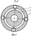
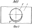
На фиг.1 представлен общий вид среднего клапана; на фиг.2 разрез А-А на фиг.1; на фиг.3 вид Б на фиг.1. Figure 1 presents a General view of the middle valve; figure 2 section aa in figure 1; figure 3 view B in figure 1.
Срезной клапан состоит из полого корпуса 1, внутри которого размещено седло 2, закрепленное на срезных шпильках 3. Седло уплотнено в корпусе с помощью эластичного элемента 4. Ниже седла 2 в корпусе 1 выполнено радиальное отверстие 5 с фигурной фаской 6. В нижней части корпуса 1 выполнен ограничительный бурт 7. Отверстие 5 в корпусе 1 ориентировано оппозитно по отношению верхнего наклонного торца седла 2. The shear valve consists of a
Верхний торец 8 седла 2 представляет собой наклонную плоскость по отношению к оси седла. Перпендикулярно наклонной плоскости 8 выполнено дополнительное отверстие 9, ось которого пересекается с осью центрального отверстия седла на наклонной плоскости 8 верхнего торца. Сбрасываемый шар обозначен позицией 10. The upper end 8 of the
Срезной клапан работает следующим образом. Shear valve operates as follows.
После спуска в скважину колонны лифтовых труб с пакером и срезным клапаном, расположенным ниже пакера, с устья сбрасывается шар 10, который садится на посадочную фаску отверстия 9 верхнего наклонного торца 8 седла 2. Далее на устье скважины создается расчетное избыточное гидравлическое давление, при котором происходит закрепление пакера в эксплуатационной колонне скважин. Затем при давлении, превышающем расчетное, происходит срез шпилек 3, в результате чего седло 2 с шаром 10 устремляется вниз до посадки нижнего торца седла в ограничительный бурт 7 корпуса 1. Одновременно шар 10 под воздействием потока жидкости скатывается по наклонной плоскости верхнего торца 8 седла 2, фигурной фаске 6 отверстия 5 и далее под воздействием веса падает в межтрубное пространство скважины на забой. При этом поток жидкости вместе с шаром 10 проходит через радиальное отверстие 5, в результате чего происходит сброс избыточного давления, что исключает возможность гидравлического удара при срезе шпилек 3, что имеет место в процессе закрепления пакеров в скважинах. After the column of elevator pipes with a packer and a shear valve located below the packer is lowered into the well, a ball 10 is dropped from the mouth, which sits on the landing chamfer of hole 9 of the upper inclined end face 8 of the
Таким образом, предлагаемая конструкция срезного клапана имеет следующие технико-экономические преимущества:
повышенную надежность срабатывания срезного клапана;
предотвращение падения седла на забой скважины;
исключение гидравлического удара;
возможность повторного использования седла срезного клапана.Thus, the proposed shear valve design has the following technical and economic advantages:
increased reliability of operation of the shear valve;
prevention of saddle falling on the bottom of the well;
elimination of water hammer;
possibility of reuse of the shear valve seat.
Claims (2)
Priority Applications (1)
| Application Number | Priority Date | Filing Date | Title |
|---|---|---|---|
| SU5023321 RU2055152C1 (en) | 1991-11-25 | 1991-11-25 | Valve |
Applications Claiming Priority (1)
| Application Number | Priority Date | Filing Date | Title |
|---|---|---|---|
| SU5023321 RU2055152C1 (en) | 1991-11-25 | 1991-11-25 | Valve |
Publications (1)
| Publication Number | Publication Date |
|---|---|
| RU2055152C1 true RU2055152C1 (en) | 1996-02-27 |
Family
ID=21594961
Family Applications (1)
| Application Number | Title | Priority Date | Filing Date |
|---|---|---|---|
| SU5023321 RU2055152C1 (en) | 1991-11-25 | 1991-11-25 | Valve |
Country Status (1)
| Country | Link |
|---|---|
| RU (1) | RU2055152C1 (en) |
Cited By (2)
| Publication number | Priority date | Publication date | Assignee | Title |
|---|---|---|---|---|
| RU2386784C1 (en) * | 2009-01-30 | 2010-04-20 | Открытое акционерное общество "Татнефть" им. В.Д. Шашина | Packer drillable |
| RU202002U1 (en) * | 2020-08-07 | 2021-01-27 | Общество с ограниченной ответственностью "Российская инновационная топливно-энергетическая компания" (ООО "РИТЭК") | ACTIVATION VALVE |
-
1991
- 1991-11-25 RU SU5023321 patent/RU2055152C1/en active
Non-Patent Citations (2)
| Title |
|---|
| 1. Composite Catalog of oil Field Equipement and services, 1986 - 1987, v.1, p.33, model "E". * |
| 2. Патент США N 3332497, кл. 166-224, 1967. * |
Cited By (2)
| Publication number | Priority date | Publication date | Assignee | Title |
|---|---|---|---|---|
| RU2386784C1 (en) * | 2009-01-30 | 2010-04-20 | Открытое акционерное общество "Татнефть" им. В.Д. Шашина | Packer drillable |
| RU202002U1 (en) * | 2020-08-07 | 2021-01-27 | Общество с ограниченной ответственностью "Российская инновационная топливно-энергетическая компания" (ООО "РИТЭК") | ACTIVATION VALVE |
Similar Documents
| Publication | Publication Date | Title |
|---|---|---|
| US6155342A (en) | Proppant containment apparatus | |
| NO302910B1 (en) | Device for gravel packing of oil well | |
| RU2055152C1 (en) | Valve | |
| RU2185497C1 (en) | Method of hydraulic jet perforation of wells and device for its embodiment | |
| RU2123577C1 (en) | Device for cleaning well-adjoining zone in productive oil beds | |
| CA1058477A (en) | Valve assembly for the remote control of fluid flow having an automatic time delay | |
| RU2042796C1 (en) | Device for well hydraulic perforation | |
| RU2054522C1 (en) | Hydraulically actuated packer | |
| RU22177U1 (en) | HYDRAULIC PERFORATOR | |
| SU1546614A1 (en) | Device for cementing wells | |
| SU945386A1 (en) | Borehole shutoff valve | |
| RU2055154C1 (en) | Bottom-hole packer-safety valve | |
| SU977711A1 (en) | Checking valve for casing strings | |
| SU933954A1 (en) | Apparatus for constructing gravel filter | |
| SU1379451A1 (en) | Arrangement for cementing casing in well | |
| RU25759U1 (en) | SECTIONAL HYDROABRASIVE PERFORATOR | |
| SU1078028A1 (en) | Hydraulic jar | |
| RU2101472C1 (en) | Design of well | |
| SU926236A1 (en) | Device for blowing-up deep-well shooting devices | |
| SU1615332A1 (en) | Plugging arrangement for isolating trouble zones in wells packed with plugging systems | |
| SU968329A1 (en) | Apparatus for sealing-away the annulus of well | |
| SU1276800A1 (en) | Drilling tool | |
| SU1283356A1 (en) | Casing cementing apparatus | |
| SU465471A1 (en) | Separator | |
| SU1263816A1 (en) | Apparatus for reverse cementing of casings |