RU2044576C1 - Method and apparatus for loose material clearing - Google Patents
Method and apparatus for loose material clearing Download PDFInfo
- Publication number
- RU2044576C1 RU2044576C1 SU5001228A RU2044576C1 RU 2044576 C1 RU2044576 C1 RU 2044576C1 SU 5001228 A SU5001228 A SU 5001228A RU 2044576 C1 RU2044576 C1 RU 2044576C1
- Authority
- RU
- Russia
- Prior art keywords
- cleaning
- cleaned
- gas
- bulk material
- container
- Prior art date
Links
Images

Classifications
-
- B—PERFORMING OPERATIONS; TRANSPORTING
- B22—CASTING; POWDER METALLURGY
- B22C—FOUNDRY MOULDING
- B22C5/00—Machines or devices specially designed for dressing or handling the mould material so far as specially adapted for that purpose
- B22C5/18—Plants for preparing mould materials
Landscapes
- Engineering & Computer Science (AREA)
- Mechanical Engineering (AREA)
- Cleaning In General (AREA)
- Molds, Cores, And Manufacturing Methods Thereof (AREA)
Abstract
Description
Изобретение относится к способу (механической) очистки поверхности(ей) частиц загрязненного насыпного материала, в частности (дополнительной) очистки термически (предварительно) регенерированного песка, в частности литейного горелого формовочного песка. The invention relates to a method for (mechanically) cleaning the surface (s) of particles of contaminated bulk material, in particular (additional) cleaning thermally (previously) regenerated sand, in particular foundry burned foundry sand.
Настоящее изобретение относится к устройству для осуществления названного выше способа со снабженной впуском и выпуском для насыпного материала емкостью, оснащенной с целью образования псевдоожиженного слоя газопроницаемым основанием для набегающего потока, к которому от источника псевдоожижающего газа подается псевдоожижающий газ. The present invention relates to a device for carrying out the aforementioned method with a container equipped with an inlet and outlet for bulk material, equipped for the purpose of forming a fluidized bed with a gas-permeable base for the free flow, to which a fluidizing gas is supplied from the source of the fluidizing gas.
При самых разных технологических процессах с применением насыпного материала (например, песка) после осуществления соответствующего процесса этот насыпной материал в общем получается в загрязненной форме и согласно этому ранее он затем не только квалифицировался как продукт отхода, но соответственно также обрабатывался, при этом его сваливали в отвалы или устраняли каким-либо иным образом (и при этом не использовали при определенных обстоятельствах даже для частичного повторного применения). In a variety of technological processes using bulk material (for example, sand), after the implementation of the corresponding process, this bulk material is generally obtained in contaminated form and, according to this, it was then not only qualified as a waste product, but was also processed accordingly, and it was dumped in dumps or disposed of in any other way (and at the same time they were not used under certain circumstances even for partial reuse).
Это является действительным, например, в отношении получающихся с давних пор в качестве отходов в больших количествах литейных горелых формовочных песков, обрабатываемых в качестве формовочных материалов неорганическими и/или органически-химическими связующими средствами и после процесса плавки, в частности вследствие добавленных ранее связующих средств, настолько загрязненных, что литейный горелый формовочный песок как таковой (то есть, следовательно, без регенерации) невозможно использовать вновь без дополнительных мероприятий. Регенерация и тем самым (по меньшей мере частичное) обратное получение загрязненного насыпного материала в названном выше в качестве примера случае предполагает, что оболочки из связующего средства и прочие загрязнения, состоящие в основном, из кварца, частиц песка, отделяются от них и сепарируются. This is true, for example, with respect to waste materials obtained in ancient times in large quantities of foundry burned molding sands, processed as molding materials with inorganic and / or organic-chemical binders and after the melting process, in particular due to previously added binders, so polluted that the foundry burned foundry sand as such (that is, therefore, without regeneration) cannot be used again without additional measures. The regeneration and thereby (at least partial) reverse production of contaminated bulk material in the above-mentioned case implies that shells from a binder and other contaminants, consisting mainly of quartz, sand particles, are separated from them and separated.
Такого рода оболочки из связующего средства возникают в случае литейного (горелого) формовочного песка при связанных неорганическим путем формовочных песках, в частности, потому, что в общем случае добавленный в качестве формовочного материала бентонит в зависимости от тепловой нагрузки при литье в основном в форме оболочки фиксируется на поверхности частиц песка за счет шамотизации (солитизации). Далее клареновый уголь и добавки, его образующие, также представляют собой загрязнения использованного для литья формовочного песка (литейного горелого формовочного песка). This kind of shell from a binder occurs in the case of foundry (burnt) foundry sand with inorganically bonded molding sands, in particular because in the general case, bentonite added as a molding material, depending on the heat load during casting, is mainly fixed in the form of a shell on the surface of sand particles due to chamotization (solitization). Further, clarin coal and additives forming it also constitute pollution used for molding foundry sand (foundry burned foundry sand).
Известны изобретения (заявки ФРГ N 4008849, 3103030, 3815877, 3019069 и патент США N 2783511), в которых уже предлагались технологии регенерации литейных горелых формовочных песков, однако они не приводят к удовлетворительным результатам ни с технической, ни с экономической точек зрения. В заявке ФРГ N 4008849 хотя и предлагаются способ и устройство для регенерации литейных горелых формовочных песков, приводящие по сравнению с более ранним уровнем техники к очень существенным техническим и тем самым также экономическим улучшениям, тем не менее выявилось то, что также эта технология еще может быть улучшена. Known inventions (applications of Germany N 4008849, 3103030, 3815877, 3019069 and US patent N 2783511), which have already proposed technologies for the regeneration of foundry burned molding sand, but they do not lead to satisfactory results either from a technical or economic point of view. In the application of Germany N 4008849, although a method and device for the regeneration of foundry burned molding sands are proposed, which lead to very significant technical and thereby also economic improvements compared with the prior art, nevertheless it was revealed that this technology can still be improved.
Качество регенератора для (возможно более) неограниченной повторной применяемости для различных способов формовки характеризуется параметрами: величина рН; солитизация; отмученный материал; общее содержание С; потери прокаливания и размер частиц < 90 мкм, причем (допустимые) предельные величины этих параметров для каждого процесса формовки определены соответственно и установлены на основании соответствующих опытов. The quality of the regenerator for (possibly more) unlimited re-applicability for various molding methods is characterized by the following parameters: pH value; solitization; elutriated material; total content C; loss of calcination and particle size <90 μm, moreover, the (permissible) limiting values of these parameters for each molding process are determined accordingly and established on the basis of relevant experiments.
Если эти предельные величины параметров превышаются, то хотя повторная применяемость регенерированного литейного горелого формовочного песка в принципе также является возможной, но лишь в соответствующих так называемых оборотных формовочных материалах. If these limit values of the parameters are exceeded, then although the repeated applicability of the regenerated foundry burned molding sand is in principle also possible, but only in the corresponding so-called reverse molding materials.
Регенерат, полученный по способу тепловой подготовки литейного горелого формовочного песка, уже имеет сравнительно высокое качество, но все еще содержит составляющие науглероженных смол, добавки и/или шамот на поверхности частиц, а также нежелательные (в связи с тем, что они мешают) тонкие составляющие. Для оптимальной регулировки желаемого, соответственно требуемого, самого по себе качества регенерата было бы поэтому необходимым освободить регенерат от этих загрязнений. The regenerate obtained by the method of heat treatment of foundry burning foundry sand already has a relatively high quality, but still contains components of carburized resins, additives and / or chamotte on the surface of the particles, as well as undesirable (due to the fact that they interfere) fine components . For optimal adjustment of the desired, respectively required, quality of the regenerate itself, it would therefore be necessary to free the regenerate from these contaminants.
Если при такого рода (дополнительной) очистке рассматривать механическую (дополнительную) очистку, то следует установить, что при желательной сохраняющей частицы механической очистке насыпного материала эффект очистки в основном достигается за счет эффекта трения, соответственно истирания, а именно, когда отдельные насыпные материалы (частицы пека) с трением друг о друга перемещаются друг относительно друга. При этом слишком большая относительная скорость частиц насыпного материала друг относительно друга или же относительно других элементов очистки является критичной в той мере, что при слишком интенсивном перемещении (дополнительно) очищаемых частиц насыпного материала может происходить как уменьшение размеров частиц, разрушение частиц и/или повреждение поверхностей частиц, существенное разрушение от износа элементов очистки вследствие отражательных эффектов с соответствующей (слишком высокой) энергией импульса. If mechanical (additional) cleaning is considered in this kind of (additional) cleaning, then it should be established that with the desired particle-preserving mechanical cleaning of bulk material, the cleaning effect is mainly achieved due to the effect of friction, respectively abrasion, namely, when individual bulk materials (particles pitch) with friction against each other move relative to each other. Moreover, an excessively large relative velocity of the particles of bulk material relative to each other or relative to other cleaning elements is critical to the extent that when the (additionally) cleaned particles of the bulk material are too intensively moved, particle size reduction, particle destruction and / or surface damage can occur particles, a significant deterioration from wear of the cleaning elements due to reflective effects with the corresponding (too high) pulse energy.
Известно несколько способов и устройств, с помощью которых обеспечивается механическое удаление такого рода загрязнений. При этом создаются эффекты отражения и трения частиц песка как между собой, так и с неподвижными или подвижными частями аппарата. В качестве примера ударно-отражательные мельницы, шаровые мельницы, вибрационные горшки и очистные барабаны, а также особенно часто применяемые ударно-отражательные установки по Якобу, Симпсону и Вебаку. Для того, чтобы удерживать повреждения и разрушения частиц как можно меньшими, делаются попытки с помощью надлежащих мероприятий, например наклонной установки отражательных поверхностей и т.д. удерживать более низкими силы соударения и делать более эффективными эффекты трения. Several methods and devices are known by which mechanical removal of such contaminants is provided. In this case, the effects of reflection and friction of sand particles are created both among themselves and with stationary or moving parts of the apparatus. As an example, impact-reflective mills, ball mills, vibratory pots and treatment drums, as well as the most commonly used impact-reflective plants according to Jacob, Simpson and Webuck. In order to keep damage and destruction of particles as small as possible, attempts are made using appropriate measures, for example, inclined installation of reflective surfaces, etc. to keep lower impact forces and to make friction effects more effective.
Наиболее близким к предлагаемому являются способ и устройство [1] в котором очистка материала осуществляется за счет трения частиц друг о друга при подаче в объем материала сжатого воздуха, это устройство включает емкость с впуском и выпуском очищаемого материала и по меньшей мере одним соединенным с источником газа под повышенным давлением соплом. Closest to the proposed are the method and device [1] in which the material is cleaned by rubbing particles against each other when compressed air is fed into the material volume, this device includes a container with the inlet and outlet of the material to be cleaned and at least one connected to a gas source under high pressure nozzle.
Общим для всех этих устройств, соответственно осуществляемых с их помощью способов, является существенный недостаток относительно большого разрушения частиц, которое в общем является тем большим, чем более высокими являются требования по качеству к регенерату, так как при сравнительно высоком требовании к качеству по логике и согласно этому последовательным образом устанавливают скорости отражения соответственно высокими, увеличивают количество прохождений через очистную аппаратуру, но при этом одновременно помимо относительно хорошего эффекта очистки приходят к высокой степени разрушения частиц. Common to all these devices, respectively carried out using their methods, is a significant drawback of relatively large destruction of particles, which in general is the greater, the higher are the quality requirements for regenerate, since with a relatively high quality requirement by logic and according to the succession of reflection is set accordingly high, the number of passes through the treatment equipment is increased, but at the same time, in addition to the relatively The overall cleaning effect results in a high degree of particle destruction.
Цель изобретения создание способа устройства, с помощью которых загрязненные поверхности частиц насыпного материала могут (механически) очищаться, соответственно дополнительно очищаться в отношении частиц. The purpose of the invention is the creation of a method of device with which the contaminated surfaces of the particles of bulk material can be (mechanically) cleaned, respectively further cleaned in relation to the particles.
Цель достигается тем, что на очищаемый, соответственно дополнительно очищаемый, насыпной материал подают находящийся под избыточным давлением поток газа и за счет этой подачи газа приводят его в псевдоожиженное состояние, очистку осуществляют с предупреждением нагрузок от ударов частиц с неподвижными или подвижными стенками, соответственно отражения от них, только за счет нагрузки (поверхности) частиц от трения, истирания, характеризуется по меньшей мере одним расположенным выше основания для набегающего потока соплом, поток сжатого газа которого направлен внутрь псевдоожиженного слоя, в котором ввиду целесообразности находится очищаемый, соответственно дополнительно очищаемый, насыпной материал. The goal is achieved in that a gas stream under excess pressure is fed to a cleaned, respectively additionally cleaned, bulk material and due to this gas supply it is brought into a fluidized state, cleaning is carried out with the prevention of loads from impacts of particles with fixed or moving walls, respectively, reflection from of them, only due to the load (surface) of the particles from friction, abrasion, is characterized by at least one nozzle located above the base for the incoming flow, the flow of compressed g the base of which is directed inside the fluidized bed, in which, due to expediency, there is a bulk material to be cleaned, respectively additionally cleaned.
При этом скорость звука газа в сопле достигается уже при предварительном давлении перед соплами около 2,3 бар абс. при увеличении предварительного давления скорость набегающего потока (скорости звука) остается постоянной, в то же время масса притекающего газа (и тем самым импульс) при увеличении давления (тем не менее) растет. In this case, the sound velocity of the gas in the nozzle is reached even at a preliminary pressure in front of the nozzles of about 2.3 bar abs. with an increase in the preliminary pressure, the speed of the incident flow (sound velocity) remains constant, at the same time, the mass of the incoming gas (and thus the momentum) increases with increasing pressure (nevertheless).
Время пребывания, в течение которого эти эффекты истирания являются эффективными, может быть увеличено практически до любого значения. Отсюда следует, что за счет предлагаемого способа действительно достигается желаемый идеальный вид механической регенерации песка исключительно за счет истирания приставших оболочек связующего средства или других загрязнений. The residence time during which these abrasion effects are effective can be increased to almost any value. It follows that due to the proposed method, the desired ideal form of mechanical sand regeneration is really achieved solely due to abrasion of adhering shells of a binder or other contaminants.
При осуществлении изобретения сопла могут размещаться со смещением друг относительно друга по высоте и/или по боку, так что не может происходить соударения потоков песка, ускоренных противоположными струями воздуха. In the practice of the invention, the nozzles can be displaced relative to each other in height and / or on the side, so that there cannot be collisions of sand flows accelerated by opposing jets of air.
Предлагаемый способ представляет возможность того, чтобы процесс очистки происходил также при высокой температуре. За счет этого могут термическим путем удаляться органические составляющие, например, состоящие из остатков синтетических связующих средств. Таким образом также является возможным выжигать с образованием безвредных остаточных веществ такие органические соединения, которые загрязняют пыли, комбинировать в один переход термическую и механическую операции основательной регенерации песка. The proposed method represents the possibility that the cleaning process also occurs at high temperature. Due to this, organic components, for example, consisting of residues of synthetic binders, can be thermally removed. Thus, it is also possible to burn such organic compounds that pollute dust with the formation of harmless residual substances, to combine the thermal and mechanical operations of thorough sand regeneration in one transition.
Эта экономически очень положительная возможность дополняется некоторыми еще более значительными преимуществами. Псевдоожиженный слой следует собственным, отличным от пневматической транспортировки законам. Отсюда следует существенно более благоприятный способ действия, так как для псевдоожижения твердого вещества требуются лишь сравнительно малые затраты энергии. Для притекающих в поперечном направлении воздушных масс также является достаточной лишь малая энергия для того, чтобы производить в псевдоожиженном слое описанные выше феномены потока. Отсюда суммарно получаются затраты энергии, составляющие лишь приблизительно 20% от требуемого для обычных пневматических способов потребления энергии. Эти экономические преимущества дополняются высоким выходом высококачественного регенерата песка с малыми потерями частиц материала. This economically very positive opportunity is complemented by some even more significant benefits. The fluidized bed follows its own laws that are different from pneumatic transportation. This implies a significantly more favorable mode of action, since only relatively low energy costs are required for fluidization of a solid. For the air masses flowing in the transverse direction, only a small amount of energy is also sufficient to produce the flow phenomena described above in the fluidized bed. From this, total energy costs are obtained, constituting only approximately 20% of the energy required for conventional pneumatic methods. These economic benefits are complemented by a high yield of high-quality sand regenerate with low loss of material particles.
Большой выигрыш заключается в меньшем разрушении частиц материала и меньших затратах на транспортировку, новый песок, отвалы. Разрушается частиц приблизительно на 15 мас. меньше. Средний размер частиц в составляющей > 0,09 в ходе очистки снижается приблизительно на 10% при очистке в течение 1 ч. The big gain lies in less destruction of material particles and lower transportation costs, new sand, dumps. Destroys particles by approximately 15 wt. less. The average particle size in the component> 0.09 during cleaning decreases by approximately 10% when cleaning within 1 hour
Согласно способу предусматривается, что поток сжатого газа направляют на / в очищенный насыпной материал по меньшей мере в одном месте подачи, причем одно место подачи сжатого газа располагают в краевой зоне соответственно очищаемого количества насыпного материала, причем оно также может находиться внутри его. According to the method, it is provided that the stream of compressed gas is directed to / into the cleaned bulk material in at least one supply point, wherein one compressed gas supply point is located in the edge zone of the correspondingly cleaned amount of bulk material, and it can also be inside it.
Причем, первому месту подачи сжатого газа в основном противолежит по меньшей мере второе место подачи сжатого газа, так что при определенных обстоятельствах в нескольких местах, соответственно, являясь следствием нескольких мест-виновников, возникает такое положение, что очищаемый насыпной материал находится в зоне (по меньшей мере) двух в основном противоположных друг другу потоков газа и особенно интенсивно (дополнительно) очищается, причем на эффекты трения, соответственно истирания, накладывается (точно) дозируемый отражательный эффект между частицами (но не со стенками или встроенными элементами) за счет выбора состояния псевдоожиженного слоя (более или менее разрыхленного) и импульса струи газа (предварительное давление перед соплом) лишь в соответствии с различной глубиной проникновения в слой. Moreover, at least the second compressed gas supply point is mainly opposed to the first compressed gas supply point, so that under certain circumstances, in several places, respectively, as a result of several culprit sites, such a situation arises that the bulk material to be cleaned is in the zone ( at least) of two basically opposite gas flows and is especially intensively (additionally) cleaned, moreover, the dosed reflective effect is superimposed (precisely) on the effects of friction, respectively abrasion the effect between particles (but not with walls or built-in elements) due to the choice of the state of the fluidized bed (more or less loosened) and the momentum of the gas stream (preliminary pressure in front of the nozzle) only in accordance with different penetration depths into the layer.
Сжатый газ направляют к одному по меньшей мере месту подачи сжатого газа по касательной к наружной поверхности очищаемой массы насыпного материала, за счет чего, когда это мероприятие реализуют в двух или большем количестве мест, очищаемый насыпной материал может приводиться во вращательное движение, положительно влияющее на желаемый эффект, причем эффект трения может быть усилен с помощью предназначенных для этого износа стойких стенок, соответственно износа стойких встроенных элементов. Compressed gas is directed to at least one compressed gas supply point tangentially to the outer surface of the bulk material to be cleaned, due to which, when this measure is implemented in two or more places, the bulk material to be cleaned can be rotated, which positively affects the desired effect, and the effect of friction can be enhanced with the use of resistant walls intended for this wear, respectively, wear of resistant built-in elements.
Интенсивность подачи одного (преимущественно всех) места подачи сжатого газа является регулируемой для того, чтобы подача сжатого газа могла согласовываться с соответствующей технологической задачей, когда используют сжатый газ (сжатый воздух). The supply rate of one (mainly all) compressed gas supply point is adjustable so that the compressed gas supply can be matched to the corresponding technological task when using compressed gas (compressed air).
Против по меньшей мере первого сопла на противолежащей стороне псевдоожиженного слоя соответственно очищаемого насыпного материала расположено по меньшей мере одно второе сопло, интенсивность потока по меньшей мере одного (преимущественно всех) сопла (сопел) может быть устанавливаемой, то есть управляемой или регулируемой. At least one second nozzle is located against at least the first nozzle on the opposite side of the fluidized bed of the respectively cleaned bulk material, the flow rate of at least one (mainly all) nozzle (s) can be set, that is, controlled or adjustable.
С технологических точек зрения в устройстве может предусматриваться несколько сопел, соответственно расположенных попарно друг против друга таким образом, что центральные оси сопел образуют параллели, расположенные под углом друг к другу или находятся на одной общей линии. From technological points of view, the device may provide several nozzles, respectively arranged in pairs opposite each other so that the central axis of the nozzles form parallels that are at an angle to each other or are on the same common line.
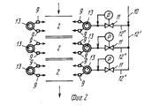
На фиг. 1 показана схема предлагаемого устройства, вид сбоку; на фиг.2 схема направления сжатого газа. In FIG. 1 shows a diagram of the proposed device, side view; figure 2 diagram of the direction of the compressed gas.
На фиг. 1 показано обозначенное позицией 1 устройство для механической дополнительной очистки термически (предварительно) регенерированного литейного горелого формовочного песка 2 с впуском для насыпного материала, снабженное выпуском для насыпного материала, емкостью 3, являющейся прямоугольной, соответственно, конической по отношению к ее вертикальной оси 4 симметрии. In FIG. 1 shows a device for mechanical additional cleaning of a thermally (pre) regenerated foundry burned
Для образования псевдоожиженного слоя в зоне дополнительно регенерируемого литейного горелого формовочного песка 2 емкость 3 снабжена перфорированным днищем 16 с газопроницаемым основанием 5 для набегающего потока. Газопроницаемое основание 5 состоит, например, из шариковой засыпки. Снизу через трубопровод 6 от неизображенного источника подается сжатый воздух в направлении стрелки 7 псевдоожижающим вихревым воздушным потоком. For the formation of a fluidized bed in the area of the additionally regenerated foundry burning
Выше основания 5 для набегающего потока в зоне пвседоожиженного слоя 8 расположены сопла 9, которые соответственно попарно в основном противолежат друг другу и которые запитываются от неизображенного источника сжатого газа в направлении стрелки 10 через совместный дроссельный орган 11, расположенный в трубопроводе 12 для подвода сжатого воздуха, и питающий кольцевой трубопровод 13, соединенный с соплами 9. При этом трубопровод 12 для подвода сжатого воздуха и кольцевой трубопровод 13 могут соединяться с отдельным (единичным) дроссельным органом 11 так, чтобы интенсивность подачи к очищаемому литейному горелому формовочному песку 2 на всех соплах 9 устанавливалась равномерно: однако от трубопровода 12'' для подвода сжатого воздуха могут ответвляться несколько (фиг.2, вид сверху) подводящих трубопроводов 12'' для сжатого воздуха, в которых соответственно расположен дроссельный орган 11 так, что интенсивность подачи к очищаемому дополнительно литейному горелому формовочному песку 2 в различных зонах псевдоожиженного слоя может устанавливаться соответственно по разному. Соответствующая возможность может предусматриваться не только в случае примера осуществления согласно фиг.2 в различных зонах псевдоожиженного слоя, но при определенных обстоятельствах в одной зоне может предусматриваться различная интенсивность подачи в том случае, если перед соплами 9 располагают непосредственно собственный дроссельный орган 11. Above the
Емкость 3 ни в коем случае не должна иметь прямоугольное (коническое) поперечное сечение, она может, например, иметь круглую форму. Круглое поперечное сечение емкости 3 (по меньшей мере, в зоне псевдоожиженного слоя 8) является целесообразным, когда по меньшей мере сопла 9 расположены таким образом, что регенерируемый насыпной материал (песок 2) (соответственно псевдоожиженный слой 8) во время работы должен приводиться во вращательное движение, например, вокруг оси 4 симметрии вращения емкости 3.
В емкости 3 могут располагаться проходящие, начиная с зоны 3' успокоения, до места сразу над основанием 5 для набегающего потока псевдоожиженного слоя 8 перегородки, подразделяющие свободный внутренний объем емкости по меньшей мере на два (или при определенных обстоятельствах также большее количество) сектора. Тем самым предупреждается обратное перемешивание уже в значительной степени очищенного насыпного материала с вновь загруженным материалом. Тем самым как бы включают друг за другом несколько псевдоожиженных слоев.
В случае псевдоожиженных слоев с круглым поперечным сечением подразделение может осуществляться за счет концентрических зон или расположенных друг над другом псевдоожиженных слоев. In the case of fluidized beds with a circular cross-section, the subdivision can be carried out by concentric zones or fluidized beds located one above the other.
Диаметр истечения сопел 9 при названном выше примере осуществления составляет 3,4 мм, однако он мог бы быть как меньшим, так и большим. The outflow diameter of the
Емкость 3 в зоне псевдоожиженного слоя 9 может быть снабжена проходящей вокруг резиновой облицовкой 14, в верхней зоне псевдоожиженного слоя 8 над соплами емкости 3 могут располагаться один, соответственно несколько неизображенных теплообменников, с помощью которого (которых) вновь используемое тепло может обратно получаться из процесса дополнительной очистки, в частности тогда, когда псевдоожиженный слой дополнительной очистки включен вслед за термическим псевдоожиженным слоем. The
Очищаемый материал подается в емкость 3 снизу через впуск 17. The material to be cleaned is fed into the
Газ, введенный согласно стрелкам 7, 10, через трубопроводы 6, 12, 12' в устройство 1, попадает из участка 3' емкости 3 после выхода из псевдоожиженного слоя 8 и из подлежащего дополнительной очистке горелого формовочного песка 2 вверх, и наконец, выходит согласно стрелке 15 из устройства 1. The gas introduced in accordance with
С помощью предлагаемого изобретения были созданы способ и устройство для его осуществления, благодаря которым подлежащий очистке насыпной материал, который в общем случае до этого уже был технологически использован, исключительно (механически) очищается, соответственно дополнительно очищается, а именно при исключительном (регулируемом) сохранении частиц с невероятно эффективной степенью очищающего действия. Using the present invention, a method and device for its implementation were created, thanks to which the bulk material to be cleaned, which in the general case had already been technologically used before, is exclusively (mechanically) cleaned, accordingly it is further cleaned, namely, with exceptional (controlled) particle preservation with an incredibly effective degree of cleansing action.
Claims (12)
Applications Claiming Priority (2)
| Application Number | Priority Date | Filing Date | Title |
|---|---|---|---|
| DEP4035263.3 | 1990-11-02 | ||
| DE19904035263 DE4035263C2 (en) | 1990-11-02 | 1990-11-02 | Method and device for cleaning bulk goods |
Publications (1)
| Publication Number | Publication Date |
|---|---|
| RU2044576C1 true RU2044576C1 (en) | 1995-09-27 |
Family
ID=6417741
Family Applications (1)
| Application Number | Title | Priority Date | Filing Date |
|---|---|---|---|
| SU5001228 RU2044576C1 (en) | 1990-11-02 | 1991-08-16 | Method and apparatus for loose material clearing |
Country Status (7)
| Country | Link |
|---|---|
| EP (1) | EP0483933A3 (en) |
| JP (1) | JPH04258367A (en) |
| BR (1) | BR9103860A (en) |
| CA (1) | CA2053184A1 (en) |
| DE (1) | DE4035263C2 (en) |
| MX (1) | MX9101506A (en) |
| RU (1) | RU2044576C1 (en) |
Families Citing this family (4)
| Publication number | Priority date | Publication date | Assignee | Title |
|---|---|---|---|---|
| DE4239611A1 (en) * | 1992-11-25 | 1994-05-26 | Werner Dipl Ing Brosowski | Light bulk solids grains graded in fluid bed from heavy grains through raising-lowering extraction cone - reduces energy requirement for grading grains such as cement and ore |
| DE102016225338A1 (en) * | 2016-12-16 | 2018-06-21 | Deutsches Zentrum für Luft- und Raumfahrt e.V. | Heat exchanger for heat transfer between a particulate heat transfer medium and a second medium |
| CN108575849B (en) * | 2018-05-07 | 2021-09-17 | 滨州市北海新区海缘养殖科技有限公司 | Feeding method of amplitude-variable sectional operation unmanned automatic feeding boat |
| CN110124996A (en) * | 2019-06-14 | 2019-08-16 | 潍坊天洁环保科技有限公司 | Energy-saving air-flow powder concentrator |
Family Cites Families (13)
| Publication number | Priority date | Publication date | Assignee | Title |
|---|---|---|---|---|
| US2553318A (en) * | 1949-05-20 | 1951-05-15 | Herbert S Simpson | Method of reclaiming sand |
| US2783511A (en) * | 1954-02-01 | 1957-03-05 | Hydro Blast Corp | Method for reclaiming used foundry sand |
| US2958650A (en) * | 1955-07-28 | 1960-11-01 | Houdry Process Corp | Removing contaminants from catalyst particles |
| FR2213094B1 (en) * | 1972-08-29 | 1975-03-28 | Heurtey Ind | |
| DE2708961A1 (en) * | 1977-03-02 | 1978-09-07 | Freier Grunder Eisen Metall | METHOD AND DEVICE FOR REDUCING THE RESIN CONTENT OF USED FOUNDRY SAND |
| DE3103030C2 (en) * | 1981-01-30 | 1984-05-03 | Klöckner-Humboldt-Deutz AG, 5000 Köln | Process for the extraction of foundry sand from used foundry sand |
| DE3400656A1 (en) * | 1984-01-11 | 1985-07-18 | Delta Engineering Beratung und Vermittlung Gesellschaft mbH, Irdning | Process for the regeneration of waste foundry sands |
| EP0149876A1 (en) * | 1984-01-20 | 1985-07-31 | Wheelabrator-Frye Inc. | Method of and apparatus for reclaiming casting sand |
| DE3735113A1 (en) * | 1986-10-16 | 1988-04-21 | Kloeckner Humboldt Deutz Ag | Fluidised-bed furnace for regenerating used foundry sands of varying compositions |
| JPH07104105B2 (en) * | 1987-03-17 | 1995-11-13 | 株式会社小松製作所 | Flow homogenization method for long-axis fluidized bed furnace |
| DE3815877C1 (en) * | 1988-05-09 | 1989-08-31 | Uraphos Chemie Gmbh, 6370 Oberursel, De | A process for separating off inorganic binder systems in the regeneration of used foundry sands |
| DE4190731D2 (en) * | 1990-03-20 | 1992-06-25 | Kuettner Gmbh & Co Kg Dr | Verfahren zum regenieren von giesserei-altsand |
| DE4022339A1 (en) * | 1990-07-13 | 1992-01-16 | Kloeckner Humboldt Deutz Ag | Surface cleaning of fine-grained material esp. used foundry sand - passes sand down inclined pipe into which are is blown to remove crust etc. |
-
1990
- 1990-11-02 DE DE19904035263 patent/DE4035263C2/en not_active Expired - Fee Related
-
1991
- 1991-06-29 EP EP9191250172A patent/EP0483933A3/en not_active Withdrawn
- 1991-08-09 JP JP22362591A patent/JPH04258367A/en active Pending
- 1991-08-16 RU SU5001228 patent/RU2044576C1/en active
- 1991-09-06 BR BR9103860A patent/BR9103860A/en unknown
- 1991-10-09 MX MX9101506A patent/MX9101506A/en unknown
- 1991-10-10 CA CA 2053184 patent/CA2053184A1/en not_active Abandoned
Non-Patent Citations (1)
| Title |
|---|
| Авторское свидетельство СССР N 1407592, кл. B 07B 9/00, 1988. * |
Also Published As
| Publication number | Publication date |
|---|---|
| CA2053184A1 (en) | 1992-05-03 |
| JPH04258367A (en) | 1992-09-14 |
| DE4035263C2 (en) | 1994-08-11 |
| MX9101506A (en) | 1992-07-08 |
| EP0483933A3 (en) | 1994-08-17 |
| BR9103860A (en) | 1992-08-04 |
| DE4035263A1 (en) | 1992-05-07 |
| EP0483933A2 (en) | 1992-05-06 |
Similar Documents
| Publication | Publication Date | Title |
|---|---|---|
| US2813318A (en) | Method and apparatus for treating granular material | |
| US4700766A (en) | Process and apparatus for reclaiming foundry scrap sands | |
| US3457336A (en) | Method of forming granules from molten droplets | |
| SU1351511A3 (en) | Method of producing granules in fluidized bed | |
| US4821654A (en) | Regeneration of bulk materials | |
| EA015134B1 (en) | Fluidising apparatus | |
| US4412923A (en) | Process and apparatus for extracting ions from a clear liquid or a liquid containing materials in suspension by contact with an exchange substance | |
| KR20010080164A (en) | Fluidized bed method and reactor for the treatment of catalysts and catalyst carriers | |
| RU2044576C1 (en) | Method and apparatus for loose material clearing | |
| US5291935A (en) | Process for the mechanical cleaning of foundry used sand | |
| GB1567102A (en) | Apparatus and method for cooling particulate slag | |
| US5520341A (en) | Apparatus for regenerating foundry sand | |
| GB2070973A (en) | Moving bed gas filter | |
| US4636168A (en) | Apparatus for thermal and pneumatic treatment of granular solids | |
| US3312403A (en) | Machine and process for reclaiming foundry sand | |
| GB2114017A (en) | Apparatus for reclaiming foundry sand | |
| US3694964A (en) | Abrasive blast cleaning system | |
| US3825190A (en) | Apparatus for treating granular material | |
| US4004942A (en) | Process and apparatus for cleaning particulate materials | |
| SU1572716A1 (en) | Pneumatic classifier | |
| US4207682A (en) | Fluid bed nozzle retainer | |
| RU1768347C (en) | Device for dry regeneration of sand from spent core and moulding sands | |
| GB1593008A (en) | Method and apparatus for reducing the resin content of used foundry sand | |
| WO2019202376A1 (en) | A method of regenerating foundry sand | |
| SU959895A1 (en) | Apparatus for regeneration of moulding and core mixtures |