RU2036381C1 - Injector - Google Patents
Injector Download PDFInfo
- Publication number
- RU2036381C1 RU2036381C1 SU5037127A RU2036381C1 RU 2036381 C1 RU2036381 C1 RU 2036381C1 SU 5037127 A SU5037127 A SU 5037127A RU 2036381 C1 RU2036381 C1 RU 2036381C1
- Authority
- RU
- Russia
- Prior art keywords
- nozzle
- housing
- injector
- diffuser
- divergent
- Prior art date
Links
Images
Abstract
Description
Изобретение относится к устройствам, предназначенным для распыления жидкости, и может быть использовано для работы в дождевальных установках, топливосжигающих устройствах. The invention relates to devices for spraying liquid, and can be used to work in sprinkler installations, fuel-burning devices.
Известна центробежная форсунка с подачей распыливаемой среды в камеру завихрения по тангенциальным каналам. В данном устройстве распыление среды осуществляется за счет гидродинамических сил, при этом пленка среды дробится на мелкие каплеобразные фракции и конусом под определенным углом раскрытия поступает в зону подготовки. Однако конструкция форсунки достаточно сложна из-за наличия тангенциальных каналов. Known centrifugal nozzle with the supply of the sprayed medium into the swirl chamber through tangential channels. In this device, the medium is sprayed by hydrodynamic forces, while the film of the medium is crushed into small droplet-like fractions and cones at a certain opening angle to the preparation zone. However, the design of the nozzle is quite complicated due to the presence of tangential channels.
Известна также форсунка, содержащая корпус с диффузорным выходным соплом, вставку с центральным конфузорным каналом, установленную во входном участке корпуса с возможностью осевого перемещения и с образованием с ним кольцевой резонирующей полости. Also known is a nozzle containing a housing with a diffuser outlet nozzle, an insert with a central confuser channel mounted in the input section of the housing with the possibility of axial movement and with it the formation of an annular resonating cavity.
Данное устройство не обеспечивает достаточной степени распыления при изменении определяющих распыл условий (параметры подачи, вид распыливаемой жидкости и т.д.), что в свою очередь приводит к снижению эффективности работы устройства. This device does not provide a sufficient degree of spraying when changing the conditions determining the spray (flow parameters, type of sprayed liquid, etc.), which in turn leads to a decrease in the efficiency of the device.
Целью изобретения является повышение степени распыления при обеспечении экономичности устройства. The aim of the invention is to increase the degree of atomization while ensuring the efficiency of the device.
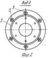
На фиг. 1 изображена предлагаемая форсунка, продольный разрез; на фиг. 2 вид по стрелке А на фиг. 1. In FIG. 1 shows the proposed nozzle, a longitudinal section; in FIG. 2 is a view along arrow A in FIG. 1.
Форсунка содержит корпус с диффузорным выходным соплом 3, вставку 1 с конфузорным центральным каналом 2, установленную во входном участке корпуса с возможностью осевого перемещения и с образованием с ним кольцевой резонирующей полости 4. Форсунка дополнительно снабжена V-образными сопловыми насадками 5, заведенными одной полкой в выполненные в корпусе в зоне диффузорного сопла 3 отверстия 7 и установленными с примыканием другой полкой к выходному срезу корпуса и к его наружной поверхности, выполненной с формой, повторяющей форму внутренней поверхности диффузорного сопла 3. The nozzle contains a housing with a
Форсунка работает следующим образом. The nozzle works as follows.
Распыливаемая среда из конфузорного центрального канала 2 поступает в кольцевую резонирующую полость 4, где происходит преобразование постоянного давления в переменное и выходит через диффузорное выходное сопло 3. The sprayed medium from the confuser central channel 2 enters the annular resonating cavity 4, where the constant pressure is converted to variable and exits through the
При необходимости регулирования качества распыла вставку 1 перемещают относительно корпуса, тем самым меняя объем кольцевой резонирующей полости 4 и как следствие частоту колебаний. Часть распыливаемой среды через отверстия 7 поступает в V-образные сопловые насадки 5 и истекает из них, образуя кольцевой ряд струй меньшего диаметра, окружающих основную центральную часть потока, выходящего из диффузорного выходного сопла. Наличие струй меньшего диаметра в пульсирующей основной струе способствует более быстрому распаду струй меньшего диаметра и росту турбулентности основной струи при взаимодействии с ней кольцевого ряда струй меньшего диаметра. При этом обеспечивается повышение степени распыления среды. If necessary, control the quality of the spray insert 1 is moved relative to the housing, thereby changing the volume of the annular resonating cavity 4 and, as a consequence, the oscillation frequency. Part of the sprayed medium through the openings 7 enters the V-shaped nozzle nozzles 5 and flows out of them, forming an annular row of jets of smaller diameter surrounding the main central part of the stream exiting the diffuser outlet nozzle. The presence of jets of a smaller diameter in a pulsating main jet contributes to a faster decay of jets of a smaller diameter and an increase in turbulence of the main jet when an annular series of jets of smaller diameter interact with it. This provides an increase in the degree of atomization of the medium.
Таким образом, эффективность от использования изобретения заключается в повышении степени распыления при обеспечении экономичности устройства за счет использования самой истекающей струи в качестве источника управляющей среды. Thus, the effectiveness of the use of the invention is to increase the degree of atomization while ensuring the efficiency of the device by using the flowing jet itself as a source of control medium.
Claims (1)
Priority Applications (1)
| Application Number | Priority Date | Filing Date | Title |
|---|---|---|---|
| SU5037127/06 RU2036381C1 (en) | 1992-04-13 | 1992-04-13 | Injector |
Applications Claiming Priority (1)
| Application Number | Priority Date | Filing Date | Title |
|---|---|---|---|
| SU5037127/06 RU2036381C1 (en) | 1992-04-13 | 1992-04-13 | Injector |
Publications (2)
| Publication Number | Publication Date |
|---|---|
| RU2036381C1 true RU2036381C1 (en) | 1995-05-27 |
| RU5037127A RU5037127A (en) | 1996-03-10 |
Family
ID=21601764
Family Applications (1)
| Application Number | Title | Priority Date | Filing Date |
|---|---|---|---|
| SU5037127/06 RU2036381C1 (en) | 1992-04-13 | 1992-04-13 | Injector |
Country Status (1)
| Country | Link |
|---|---|
| RU (1) | RU2036381C1 (en) |
Cited By (2)
| Publication number | Priority date | Publication date | Assignee | Title |
|---|---|---|---|---|
| WO2005102536A1 (en) | 2004-04-20 | 2005-11-03 | Andrey Leonidovich Dushkin | Liquid atomizer |
| RU2450866C1 (en) * | 2010-12-09 | 2012-05-20 | Государственное образовательное учреждение высшего профессионального образования "Московский авиационный институт (государственный технический университет") | Fluid sprayer |
-
1992
- 1992-04-13 RU SU5037127/06 patent/RU2036381C1/en active
Non-Patent Citations (2)
| Title |
|---|
| Авторское свидетельство СССР N 1751600, кл. F 23D 11/34, 1990. * |
| Адамов В.А. Сжигание мазута в топках котлов. Л.: Недра, 1989, с.39. * |
Cited By (2)
| Publication number | Priority date | Publication date | Assignee | Title |
|---|---|---|---|---|
| WO2005102536A1 (en) | 2004-04-20 | 2005-11-03 | Andrey Leonidovich Dushkin | Liquid atomizer |
| RU2450866C1 (en) * | 2010-12-09 | 2012-05-20 | Государственное образовательное учреждение высшего профессионального образования "Московский авиационный институт (государственный технический университет") | Fluid sprayer |
Similar Documents
| Publication | Publication Date | Title |
|---|---|---|
| RU2329873C2 (en) | Liquid sprayer | |
| US3474970A (en) | Air assist nozzle | |
| US4041984A (en) | Jet-driven helmholtz fluid oscillator | |
| US4343434A (en) | Air efficient atomizing spray nozzle | |
| US4394965A (en) | Pulsating shower using a swirl chamber | |
| US3667679A (en) | Apparatus for mixing a plurality of gaseous streams | |
| RU2036381C1 (en) | Injector | |
| SU503600A1 (en) | Jet centrifugal nozzle | |
| PL80419B1 (en) | Method of and apparatus for mixing compressible fluid media[gb1293360a] | |
| US4730774A (en) | Dual pressure compensating snowmaking apparatus | |
| RU2036379C1 (en) | Injector | |
| RU2622944C1 (en) | Acoustic nozzle of kochetov for spraying solutions | |
| US3758033A (en) | Pressure wave atomizing method | |
| RU2190483C1 (en) | Jet nozzle | |
| RU2036382C1 (en) | Injector | |
| RU2036380C1 (en) | Injector | |
| RU2008981C1 (en) | Acoustic atomizer | |
| SU1176967A1 (en) | Acoustic liquid sprayer | |
| RU2101614C1 (en) | Injector | |
| RU2010616C1 (en) | Acoustic jet | |
| RU2641275C1 (en) | Acoustic head for nozzles for spraying liquids with parabolic swirler | |
| RU2660015C1 (en) | Acoustic spray for spraying liquids | |
| SU1720730A1 (en) | Liquid discharge head | |
| RU2638348C1 (en) | Acoustic nozzle for atomization of liquids by kochetov | |
| RU2658021C1 (en) | Acoustic atomizer for spraying solutions |