RU2032103C1 - Detonation engine - Google Patents
Detonation engine Download PDFInfo
- Publication number
- RU2032103C1 RU2032103C1 SU4922269A RU2032103C1 RU 2032103 C1 RU2032103 C1 RU 2032103C1 SU 4922269 A SU4922269 A SU 4922269A RU 2032103 C1 RU2032103 C1 RU 2032103C1
- Authority
- RU
- Russia
- Prior art keywords
- engine
- shaft
- housing
- combustion chambers
- engine according
- Prior art date
Links
- 238000005474 detonation Methods 0.000 title claims description 15
- 238000002485 combustion reaction Methods 0.000 claims abstract description 32
- 239000000446 fuel Substances 0.000 claims abstract description 13
- 239000007800 oxidant agent Substances 0.000 claims description 10
- 230000007246 mechanism Effects 0.000 claims description 5
- 230000001590 oxidative effect Effects 0.000 claims 1
- 239000007789 gas Substances 0.000 abstract description 10
- QVGXLLKOCUKJST-UHFFFAOYSA-N atomic oxygen Chemical compound [O] QVGXLLKOCUKJST-UHFFFAOYSA-N 0.000 abstract description 4
- 239000001301 oxygen Substances 0.000 abstract description 4
- 229910052760 oxygen Inorganic materials 0.000 abstract description 4
- 230000000694 effects Effects 0.000 abstract description 3
- 230000004048 modification Effects 0.000 abstract 3
- 238000012986 modification Methods 0.000 abstract 3
- 239000002737 fuel gas Substances 0.000 abstract 1
- 239000000126 substance Substances 0.000 abstract 1
- 239000000203 mixture Substances 0.000 description 10
- 239000003570 air Substances 0.000 description 9
- 239000002360 explosive Substances 0.000 description 7
- 238000010586 diagram Methods 0.000 description 3
- 238000004880 explosion Methods 0.000 description 3
- 230000006835 compression Effects 0.000 description 2
- 238000007906 compression Methods 0.000 description 2
- 238000001816 cooling Methods 0.000 description 2
- 239000012080 ambient air Substances 0.000 description 1
- 230000005540 biological transmission Effects 0.000 description 1
- 238000005516 engineering process Methods 0.000 description 1
- 239000007788 liquid Substances 0.000 description 1
- 238000007789 sealing Methods 0.000 description 1
- 230000000087 stabilizing effect Effects 0.000 description 1
- 239000007858 starting material Substances 0.000 description 1
Images


Landscapes
- Output Control And Ontrol Of Special Type Engine (AREA)
Abstract
Description
Изобретение относится к двигателестроению и может применяться при создании двигателей, используемых для вращения различных механизмов и машин. The invention relates to engine building and can be used to create engines used to rotate various mechanisms and machines.
Известны двигатели внутреннего сгорания (ДВС), использующие газ в качестве топлива и применяемые для обеспечения мощностью различных объектов и устройств [1]. Known internal combustion engines (ICE), using gas as fuel and used to provide power to various objects and devices [1].
Известен двухходовой ДВС, содержащий корпус, камеры сгорания, карбюратор, компрессионную камеру, системы зажигания и охлаждения, газоходные каналы и турбину [2]. Недостатком такого ДВС является повышенная масса и низкий ресурс. Known two-way internal combustion engine containing a housing, a combustion chamber, a carburetor, a compression chamber, ignition and cooling systems, gas ducts and a turbine [2]. The disadvantage of this engine is the increased mass and low resource.
Целью изобретения является повышение эффективности за счет снижения массы и нагрузок, увеличения ресурса и упрощения конструкции. The aim of the invention is to increase efficiency by reducing weight and loads, increasing resource and simplifying the design.
Для этого двигатель может быть выполнен в одноконтурном и двухконтурном вариантах по закрытой и открытой схемам. Он содержит корпус с полым валом, на котором попарно размещены камеры сгорания, являющиеся фактически детонационными камерами. Эти камеры содержат свечи системы зажигания, а вал связан с одной стороны с магистралью подачи горючего (газа, распыленного жидкого топлива и т.п.), а с другой стороны с патрубками подвода камер сгорания. For this, the engine can be made in single-circuit and dual-circuit versions in closed and open circuits. It contains a housing with a hollow shaft, on which combustion chambers, which are actually detonation chambers, are placed in pairs. These chambers contain spark plugs, and the shaft is connected on one side to the fuel supply line (gas, atomized liquid fuel, etc.) and, on the other hand, to the pipes for supplying combustion chambers.
При выполнении двигателя в одноконтурном варианте по закрытой схеме магистраль подачи окислителя также размещена в полом валу и соединена патрубками подвода камер сгорания, а корпус выполнен герметичным и снабжен выхлопной трубой. При выполнении двигателя по открытой схеме корпус выполнен негерметичным либо отсутствует, окислителем является окружающий воздух, всасывающийся в камеры сгорания прямо из атмосферы, а выхлопные газы выбрасываются из камер сгорания прямо в окружающую среду. Полный вал при этом заканчивается выходным хвостовиком, с которого и снимается крутящий момент. When the engine is executed in a single-circuit version according to a closed circuit, the oxidizer supply line is also located in the hollow shaft and connected by nozzles for supplying the combustion chambers, and the casing is sealed and equipped with an exhaust pipe. When the engine is run in an open circuit, the casing is leaky or absent, the oxidizing agent is the ambient air that is sucked into the combustion chambers directly from the atmosphere, and exhaust gases are emitted from the combustion chambers directly into the environment. The full shaft at the same time ends with the output shaft, from which the torque is removed.
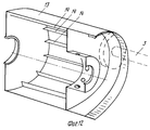
При выполнении двигателя в двухконтурном варианте он снабжен внутренним герметичным корпусом с механизмом внутреннего зацепления (зубчатым венцом), а на полом валу находится зубчатое колесо, находящееся в контакте с зубчатым колесом выходного вала (хвостовика), которое, в свою очередь, контактирует с механизмом зацепления внутреннего герметичного корпуса. Внутренний герметичный корпус размещен в основном корпусе и связан с коллектором выхлопной трубы. На внутренней поверхности внутреннего герметичного корпуса расположены газодинамические ребра. When the engine is executed in a double-circuit version, it is equipped with an internal sealed housing with an internal gearing mechanism (ring gear), and on the hollow shaft there is a gear wheel that is in contact with the gear wheel of the output shaft (shank), which, in turn, is in contact with the gearing mechanism internal tight case. The internal sealed housing is housed in the main body and is connected to the exhaust manifold. On the inner surface of the inner sealed enclosure are gas dynamic ribs.
Камера сгорания может быть выполнена трубчатой и сопловой. В первом случае она может быть снабжена на выходном срезе пластинчатым запорным клапаном и связана в торцовой части с патрубками подвода. Во втором случае в докритической части сопла может быть установлен пластинчатый запорный клапан. Патрубки подвода камер сгорания могут быть выполнены в виде нормально открытых пластинчатых клапанов. The combustion chamber can be made tubular and nozzle. In the first case, it can be equipped with a plate shut-off valve at the outlet cut and connected in the end part with supply pipes. In the second case, a plate shut-off valve can be installed in the subcritical part of the nozzle. The nozzles for supplying combustion chambers can be made in the form of normally open plate valves.
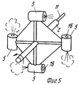
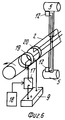
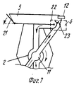
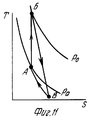
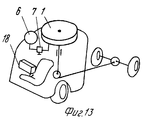
На фиг.1 показана схема двигателя в одноконтурном варианте по закрытой схеме; на фиг. 2 - то же, в двухконтурном варианте по закрытой схеме; на фиг. 3 - то же, в одноконтурном варианте по открытой схеме; на фиг.4 и 5 - варианты размещения камер сгорания на валу; на фиг.6 - электрическая схема системы зажигания с общим питанием свечей; на фиг.7 и 8 - трубчатая и сопловая камеры сгорания соответственно, вид сбоку; на фиг.9 - трубчатая камера сгорания при "открытой" схеме двигателя; на фиг.10 - примерный график изменения давления на дне трубчатой камеры сгорания; на фиг.11 - диаграмма цикла работы камеры сгорания в Т-S координатах (АБ - взрыв смеси, БВ - выброс продуктов детонации, ВА - всасывание); на фиг.12 - внутренний герметичный корпус в разрезе; на фиг.13 и 14 - примеры размещения детонационных двигателей на автомобиле и вертолете соответственно; на фиг.15 - система зажигания с индивидуальным питанием свечей; на фиг.16 - результирующий момент двигателя с двумя параметрами камер сгорания (а - первая пара, б - вторая пара, в - результирующий момент). Figure 1 shows a diagram of the engine in a single-circuit version in a closed circuit; in FIG. 2 - the same, in a double-circuit version in a closed circuit; in FIG. 3 - the same, in a single-circuit version in an open circuit; figure 4 and 5 - options for placing combustion chambers on the shaft; Fig.6 is an electrical diagram of an ignition system with a common supply of candles; 7 and 8 are a tubular and nozzle combustion chamber, respectively, side view; figure 9 is a tubular combustion chamber with an "open" engine circuit; figure 10 is an exemplary graph of pressure changes at the bottom of the tubular combustion chamber; figure 11 is a diagram of the cycle of the combustion chamber in the T-S coordinates (AB - explosion of the mixture, BV - emission of detonation products, VA - suction); on Fig - internal sealed enclosure in the context; on Fig and 14 are examples of the placement of detonation engines on a car and a helicopter, respectively; on Fig - ignition system with individual power candles; in Fig.16 - the resulting engine torque with two parameters of the combustion chambers (a - the first pair, b - the second pair, c - the resulting moment).
Двигатель состоит из корпуса 1, полого герметизированного вала 2 и выходного вала 3, впускных устройств 4 и камер 5 сгорания, источника 6 горючего (газа) с запорным элементом (редуктором) 7, питающего коллектора 8, системы зажигания с аккумулятором 9, выхлопной трубы 10, магистрали 11 окислителя. The engine consists of a
Магистраль 11 находится внутри вала 2, являющегося одновременно магистралью горючего, они жестко связаны и сообщаются с камерами 5 сгорания посредством устройств 4. Источник 6 через редуктор 7 и коллектор 8 сообщается с полостью вала 2, аккумулятор (генератор) 9 контактирует с выводами свечей 12, размещенных в камерах 5 сгорания. The
При одноконтурном выполнении двигателя вал 3 жестко связан с валом 2 и является его продолжением в виде хвостовика (фиг.1), а при двухконтурном вал 3 связан зубчатой передачей с внутренним герметичным корпусом 13, который насажен на вал 2 через подшипник с уплотнением и снабжен изнутри газодинамическими ребрами 14 и коллектором 15, связанным с трубой 10. With a single-circuit engine, the
Воздух (окислитель) в магистраль 11 может подаваться как от пневмобаллона с запорным элементом (по аналогии с подачей горючего), так и с помощью вентилятора (не показан), приводимого от вала 3, либо под действием собственного напора при размещении двигателя на движущихся объектах (машинах, вертолетах и т.п.). Air (oxidizing agent) to the
Возможно выполнение двигателя и по "открытой" схема (фиг.3), когда воздух подается не по специальной магистрали 11, а через пластинчатый клапан 16 от встречного потока воздуха, что также характерно при расположении двигателя на автомобилях, вертолетах и т.п. Корпус 1 при этом может отсутствовать. It is possible to perform the engine according to an “open” circuit (Fig. 3), when air is supplied not through a
Камеры 5 сгорания размещены на валу 2 попарно и могут быть выполнены как разнесенными (фиг.4), так и совмещенными (фиг.5) в зависимости от конкретного назначения двигателя. Важно, чтобы обеспечивалось совмещение центра масс конструкции с осью вала 2. The
Система зажигания содержит прерыватель 17, связанный с системой управления 18 двигателя и обеспечивающий требуемую частоту возникновения искрового разряда на свечах 12. Прерыватель 17 может быть выполнен в виде нормально разомкнутых контактов реле с электромагнитным управлением или по какой-либо другой известной схеме. В состав системы зажигания входят также кольцевые коллекторы 19 и 20 на валу 2 (фиг.6), связанные с проводами свечей 12. Возможен вариант, когда каждой паре камер 5 соответствуют собственные коллекторы 19 и 20, прерыватель 17 и коммутационные провода к свечам 12. The ignition system contains a
Камеры 5 сгорания могут быть выполнены как в трубчатом (фиг.7), так и в сопловом (фиг. 8) вариантах. Первый вариант характеризуется исключительной простотой, а второй - максимальным использованием энергии импульса. Камеры 5 могут содержать запорные клапаны 21 (на фиг.7,8 они показаны в пластинчатом варианте, когда они автоматически перекрывают отверстия камер 5 под действием центробежной силы), предотвращающие нежелательную утечку гремучей смеси в корпус 1 или 13. The
Для двигателей, работающих в стационарном режиме (при стабильной внешней нагрузке и с постоянной частотой срабатывания прерывателя 17), клапаны 21 могут отсутствовать, если выполняется условие: время между проскакиванием искры на свечах 12 меньше или равно времени заполнения камер 5 гремучей смесью горючего и воздуха (кислорода), т.е. когда гремучая смесь не успевает вытечь из камеры 5 в корпус 1 или 13 (фиг.9). For engines operating in stationary mode (with a stable external load and with a constant frequency of operation of the chopper 17), the
Впускные устройства 4 могут быть выполнены, например, в виде пластинчатых обратных клапанов 22 и 23. При "открытой" схеме (фиг.9) клапан 23 может отсутствовать, его роль выполняет клапан 16. Клапаны 16,21-23 выполнены стабилизирующимися центробежными силами: клапаны 16 и 21 закрыты, клапаны 22 и 23 открыты. The
В исходном положении редукторы 7 настраивают так, чтобы секундный массовый расход горючего из источника (баллона) 6 составлял при смешении с воздухом (окислителем) гремучую (детонационную) смесь. Горючее поступает в камеры 5 через коллектор 8, полость вала 2 и устройства 4, а воздух - через соответствующий коллектор и магистраль 11 при одноконтурном (фиг.1) и двухконтурном (фиг. 2) вариантах. В случае "открытой" схемы (фиг.3) воздух уже заранее заполняет камеры 5. In the initial position, the gearboxes 7 are adjusted so that the second mass flow of fuel from the source (cylinder) 6 constitutes an explosive (detonation) mixture when mixed with air (oxidizing agent). The fuel enters the
Затем осуществляют раскрутку вала 3, например, стартером и включают прерыватель 17 - на свечах 12 проскакивает искра и в камерах 5 происходит взрыв гремучей смеси. При этом давление в камерах 5 скачкообразно повышается с величины Ра до Ро (фиг.10,11), клапаны 21, если они есть, открываются избыточным давлением и продукты детонации выбрасываются наружу (в корпус 1 при одноконтурном варианте, в корпус 13 при двухконтурном варианте и в атмосферу при "открытой" схеме), создавая на валу 2 требуемый импульс крутящего момента. При взрыве в камерах 5 клапаны 22 и 23 (или 22 и 16) закрываются избыточным давлением, препятствуя нежелательному истечению газов.Then, the
Импульсный выброс продуктов детонации характеризуется нестационарным движением волн разрежения к дну камеры 5 (фиг.7 и 9) или квазистационарным истечением этих продуктов через сопло (фиг.8), но в любом случае в камере 5 возникает разрежение (когда Р < Ра, фиг.10 и 11), обеспечивающее всасывание в нее газа из полости вала 2. После наполнения камер 5 детонационной (гремучей) смесью вновь (через период tΣ, фиг.10) срабатывает прерыватель 17, обеспечивая искру на свечах 12 и взрыв смеси. Постоянное повторение этого цикла и обеспечивает функционирование двигателя.A pulsed emission of detonation products is characterized by the unsteady movement of rarefaction waves toward the bottom of chamber 5 (Figs. 7 and 9) or quasistationary outflow of these products through a nozzle (Fig. 8), but in any case, rarefaction occurs in chamber 5 (when P <P a , Fig .10 and 11), which ensures that gas is sucked into it from the cavity of the
При одноконтурном варианте (фиг.1) продукты детонации из камер 5 поступают в корпус 1, а оттуда через трубу 10 выбрасываются в атмосферу. Крутящий момент при этом от вала 2 передается непосредственно на выходной вал (хвостовик) 3. Так же момент передается и при открытой схеме (фиг.3). In the single-loop version (Fig. 1), detonation products from the
При двухконтурном варианте (фиг. 2) продукты детонации, вырываясь из камер 5 и обладая значительной скоростью, попадают на ребра 14 внутреннего корпуса 13, обеспечивая его вращение в противоположную сторону. Через зубчатую передачу вращающий момент передается на выходной вал 3. Продукты детонации из корпуса 13 через коллектор 15 выбрасываются в выхлопную трубу 10. In the double-circuit version (Fig. 2), detonation products, breaking out of the
Регулировка мощности предлагаемого двигателя осуществляется через систему управления 18 изменением периода tΣ срабатывания прерывателей 17 (т.е. свечей 12), а также изменением давления горючего газа в валу 2 и воздуха в магистрали 11 (оно может очень немного отличаться от атмосферного Ра и быть таким, чтобы преодолеть гидравлическое сопротивление магистралей и за требуемое время наполнять камеры 5 гремучей смесью).The power of the proposed engine is controlled through the
Остановка двигателя может осуществляться путем размыкания прерывателей 17 и перекрывания редуктора 7. Одновременно может быть произведена продувка полостей воздухом через магистраль 11. The engine can be stopped by opening the
Нежелательные вибрации, которые могут иметь место при работе двигателя, сводятся к минимуму очередностью срабатывания свечей 12 в камерах 5 (фиг. 16), а также инерцией вращающихся частей двигателя. Unwanted vibrations that may occur during engine operation are minimized by the sequence of operation of the
Предлагаемый двигатель может быть установлен стационарно, а также на автомобилях (фиг.13), объектах авиационной техники (фиг.14) и др. На автомобилях он может быть размещен вверху, так как благодаря значительному гироскопическому эффекту препятствует опрокидыванию. The proposed engine can be installed permanently, as well as on cars (Fig. 13), objects of aviation technology (Fig. 14), etc. On cars, it can be placed at the top, since due to the significant gyroscopic effect it prevents capsizing.
Таким образом, предлагаемый детонационный двигатель обладает высокой эффективностью: он не требует операции сжатия горючей смеси как в ДВС, сопряженной с затратами энергии; не содержит коленвала и возвратно-поступательно движущихся частей, требующих тщательного уравновешивания; прост конструктивно, обладает малой массой, не требует тщательной герметизации и может быть легко управляем. Thus, the proposed detonation engine has high efficiency: it does not require the operation of compression of the combustible mixture as in ICE, associated with the expenditure of energy; does not contain a crankshaft and reciprocating moving parts that require careful balancing; structurally simple, light in weight, does not require careful sealing and can be easily controlled.
Позволяя использовать детонационный эффект, который стараются избежать во всех ДВС, для обеспечения функционирования, двигатель не требует системы охлаждения, обладает повышенным КПД и большим ресурсом. Это позволяет широко использовать его в стационарных и движущихся объектах. Allowing to use the detonation effect, which they try to avoid in all ICEs, to ensure functioning, the engine does not require a cooling system, has an increased efficiency and a long resource. This allows you to widely use it in stationary and moving objects.
Claims (11)
Priority Applications (1)
| Application Number | Priority Date | Filing Date | Title |
|---|---|---|---|
| SU4922269 RU2032103C1 (en) | 1991-03-28 | 1991-03-28 | Detonation engine |
Applications Claiming Priority (1)
| Application Number | Priority Date | Filing Date | Title |
|---|---|---|---|
| SU4922269 RU2032103C1 (en) | 1991-03-28 | 1991-03-28 | Detonation engine |
Publications (1)
| Publication Number | Publication Date |
|---|---|
| RU2032103C1 true RU2032103C1 (en) | 1995-03-27 |
Family
ID=21566830
Family Applications (1)
| Application Number | Title | Priority Date | Filing Date |
|---|---|---|---|
| SU4922269 RU2032103C1 (en) | 1991-03-28 | 1991-03-28 | Detonation engine |
Country Status (1)
| Country | Link |
|---|---|
| RU (1) | RU2032103C1 (en) |
Cited By (1)
| Publication number | Priority date | Publication date | Assignee | Title |
|---|---|---|---|---|
| RU2166698C2 (en) * | 1996-01-26 | 2001-05-10 | Ольборг Индастриз А/С | Arrangement of inlet pipe of heat exchange unit in chimney pipe |
-
1991
- 1991-03-28 RU SU4922269 patent/RU2032103C1/en active
Non-Patent Citations (2)
| Title |
|---|
| 1. Политехнический словарь. М., СЭ, 1989, с.141, 142. * |
| 2. Изобретатель и рационализатор, 1990, N 5, с.44. * |
Cited By (1)
| Publication number | Priority date | Publication date | Assignee | Title |
|---|---|---|---|---|
| RU2166698C2 (en) * | 1996-01-26 | 2001-05-10 | Ольборг Индастриз А/С | Arrangement of inlet pipe of heat exchange unit in chimney pipe |
Similar Documents
| Publication | Publication Date | Title |
|---|---|---|
| US2397357A (en) | Reaction turbine propeller | |
| US6505462B2 (en) | Rotary valve for pulse detonation engines | |
| US4860704A (en) | Hinge valved rotary engine with separate compression and expansion sections | |
| US6886527B2 (en) | Rotary vane motor | |
| JP6132979B2 (en) | Engine that uses combustion gas as driving force | |
| US10208598B2 (en) | Rotary energy converter with retractable barrier | |
| US3552121A (en) | Means for preventing reverse water flow through exhaust pipe of a rotary piston type marine engine | |
| US3702746A (en) | Rotary free piston gas generator | |
| RU2032103C1 (en) | Detonation engine | |
| US3990228A (en) | Method and apparatus for converting heat energy into mechanical energy | |
| KR20000048672A (en) | Engine working according to the method of pulsating combustion | |
| US2581669A (en) | Gas turbine power plant with tank supplied by long conduit having volume over six times that of the intermittent combustion gas generator | |
| US3892206A (en) | Combustion device for heat motors | |
| CN101233307A (en) | internal combustion engine | |
| RU2147341C1 (en) | Gas turbine plant with combustion of fuel in constant volume | |
| US6370864B1 (en) | Turbine engine with valve mechanism and integral combustion chamber | |
| US3795230A (en) | Primary air supply for an internal combustion engine | |
| CN208778093U (en) | A kind of rotor-reciprocating engine | |
| JPH1162605A (en) | Rotary type internal combustion engine | |
| CN104279079B (en) | Implosive pusher | |
| JPH0450455A (en) | Power generating device | |
| CN110159431B (en) | Multi-cylinder turbine rotary engine | |
| RU2184262C2 (en) | Rotary power plant | |
| RU2011869C1 (en) | Gas-steam-fluid engine | |
| JPS5726204A (en) | Rotary engine with compressor |