RU2027503C1 - Pulsed-action reactor - Google Patents
Pulsed-action reactor Download PDFInfo
- Publication number
- RU2027503C1 RU2027503C1 RU92008314A RU92008314A RU2027503C1 RU 2027503 C1 RU2027503 C1 RU 2027503C1 RU 92008314 A RU92008314 A RU 92008314A RU 92008314 A RU92008314 A RU 92008314A RU 2027503 C1 RU2027503 C1 RU 2027503C1
- Authority
- RU
- Russia
- Prior art keywords
- reactor
- housing
- liquid
- discharge chamber
- source
- Prior art date
Links
- 230000010349 pulsation Effects 0.000 claims description 13
- 239000007788 liquid Substances 0.000 abstract description 25
- 238000000034 method Methods 0.000 abstract description 6
- 239000000126 substance Substances 0.000 abstract description 2
- 230000005284 excitation Effects 0.000 abstract 1
- 239000003990 capacitor Substances 0.000 description 4
- 239000003153 chemical reaction reagent Substances 0.000 description 3
- 238000004891 communication Methods 0.000 description 3
- 238000005265 energy consumption Methods 0.000 description 3
- 230000035939 shock Effects 0.000 description 3
- 238000012546 transfer Methods 0.000 description 3
- 230000015572 biosynthetic process Effects 0.000 description 2
- 238000013461 design Methods 0.000 description 2
- 230000010355 oscillation Effects 0.000 description 2
- 229910000831 Steel Inorganic materials 0.000 description 1
- 239000007795 chemical reaction product Substances 0.000 description 1
- 239000011521 glass Substances 0.000 description 1
- 230000003993 interaction Effects 0.000 description 1
- 238000012544 monitoring process Methods 0.000 description 1
- 230000003534 oscillatory effect Effects 0.000 description 1
- 230000000737 periodic effect Effects 0.000 description 1
- 239000000047 product Substances 0.000 description 1
- 230000001902 propagating effect Effects 0.000 description 1
- 239000011541 reaction mixture Substances 0.000 description 1
- 239000010959 steel Substances 0.000 description 1
Images
Landscapes
- Physical Or Chemical Processes And Apparatus (AREA)
Abstract
Description
Изобретение относится к устройствам для интенсификации массо- и теплообменных процессов в жидких средах, особенно в вязких и плохо смешиваемых жидкостях, и может быть использовано в химической, пищевой и других отраслях промышленности. The invention relates to devices for intensifying mass and heat transfer processes in liquid media, especially in viscous and poorly mixed liquids, and can be used in chemical, food and other industries.
Известен пульсационный реактор, содержащий вертикальный цилиндрический корпус с технологическими патрубками, расположенную внутри корпуса пульсационную камеру, соединенную с ней распределительную камеру и пульсопровод. Распределительная камера выполнена в виде стакана с клапанным лепестковым устройством и центральным отверстием в днище, над которым размещена пульсационная камера с закрепленным в нижней части упругим сильфонным элементом, торцовая часть которого выполнена конической, причем клапанное лепестковое устройство размещено в верхней части корпуса с перекрытием кольцевой зоны, а в нижней части корпуса установлено кольцо с отбортовкой вниз. Known pulsation reactor containing a vertical cylindrical casing with technological pipes located inside the casing of the pulsation chamber, a distribution chamber connected to it and a pulse conduit. The distribution chamber is made in the form of a glass with a valve flap device and a central hole in the bottom, above which there is a pulsation chamber with an elastic bellows element fixed at the bottom, the end part of which is conical, and the valve flap device is placed in the upper part of the housing with overlapping the annular zone, and in the lower part of the body there is a ring with a flanging down.
Недостатком этого устройства является сложность конструкции и низкая интенсивность процесса массообмена между компонентами реакционной смеси. The disadvantage of this device is the design complexity and low intensity of the mass transfer process between the components of the reaction mixture.
Целью изобретения является снижение энергозатрат и повышение эксплуатационных свойств реактора. The aim of the invention is to reduce energy consumption and increase the operational properties of the reactor.
Цель достигается за счет того, что пульсационный реактор, содержащий вертикальный цилиндрический корпус с технологическими патрубками и установленный по центру корпуса пульсопровод, сообщенный с источником пульсаций давления, снабжен импульсным дозатором, всасывающая сторона которого соединена с верхней, а нагнетательная с нижней частью корпуса. Пульсопровод размещен под днищем корпуса и подключен верхним концом к днищу, при этом источник пульсаций давления выполнен в виде полусферической камеры с установленными в ней двумя электродами, сообщенными с источником электрических импульсов. The goal is achieved due to the fact that the pulsation reactor, containing a vertical cylindrical body with technological nozzles and installed in the center of the body, the pulse conduit in communication with the source of pressure pulsations, is equipped with a pulse dispenser, the suction side of which is connected to the upper and the discharge side to the lower part of the body. The pulse line is placed under the bottom of the housing and is connected with its upper end to the bottom, while the source of pressure pulsations is made in the form of a hemispherical chamber with two electrodes installed in it, in communication with the source of electrical pulses.
При заполнении реактора жидкостью на 80-90% всасывающая сторона дозатора связана с газовой частью корпуса, что позволяет импульсно вводить газ в нижнюю (жидкостную) часть реактора. Подаваемые на электроды электрические импульсы вызывают электрические разряды в жидкости и образование ударных волн, возбуждающих гидроакустические волны давления. Эти волны, отражаясь от сферической поверхности разрядной камеры, поступают по вертикальному патрубку в нижнюю часть корпуса и распространяются в жидкости в направлении его верхней части. При этом ≈80% выделяемой при разряде энергии преобразуются в волновую энергию, что определяет высокий КПД процесса. Размещение разрядной камеры под днищем корпуса и подключение ее к днищу через вертикальный патрубок обуславливает минимальные потери при подводе волновой энергии к реакционной массе. When the reactor is filled with liquid at 80-90%, the suction side of the dispenser is connected to the gas part of the housing, which allows you to pulse to introduce gas into the lower (liquid) part of the reactor. The electrical pulses supplied to the electrodes cause electrical discharges in the liquid and the formation of shock waves, exciting hydroacoustic pressure waves. These waves, reflected from the spherical surface of the discharge chamber, pass through a vertical nozzle to the lower part of the housing and propagate in the liquid in the direction of its upper part. In this case, ≈80% of the energy released during the discharge is converted into wave energy, which determines the high efficiency of the process. The placement of the discharge chamber under the bottom of the housing and its connection to the bottom through a vertical pipe causes minimal loss when supplying wave energy to the reaction mass.
Все это существенно снижает энергозатраты и усиливает возбуждаемые в жидкости волны давления. Более сильные, чем в прототипе, волны давления позволяют за счет возрастающей вибрационной силы и силы межфазного взаимодействия Бьеркнесса удерживать в жидкости вводимый импульсно газ, образовав газожидкостную систему, и обеспечивать режим ее резонансных колебаний. При этом повышаются эксплуатационные свойства и надежность работы аппарата. All this significantly reduces energy consumption and enhances pressure waves excited in the liquid. Stronger than in the prototype, pressure waves make it possible, due to the increasing vibrational force and the Björkness interfacial interaction force, to retain pulse-injected gas in a liquid, forming a gas-liquid system, and to ensure the mode of its resonant vibrations. This increases the operational properties and reliability of the apparatus.
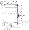
На чертеже показан пульсационный реактор. The drawing shows a pulsation reactor.
Реактор содержит вертикальный цилиндрический корпус 1 с патрубками 2 и 3 ввода реагентов и патрубком 4 отвода продуктов реакции, установленный на опорах 5. В днище 6 корпуса 1 выполнено центральное отверстие, к которому подсоединена верхняя часть вертикального патрубка (пульсопровода) 7, герметично подстыкованного снаружи к корпусу. На нижнем торце патрубка 7 закреплена разрядная камера 8, выполненная в виде полусферы 9 с двумя электродами 10, установленными с межэлектродным зазором в фокусе полусферы 9. Электроды 10 выполнены в виде стержней из тугоплавкой стали, изолированных по боковой поверхности, и соединены с полюсами высоковольтного источника электрических импульсов 11. The reactor contains a vertical
Источник электрических импульсов 11 содержит повышающий трансформатор, соединенный через выпрямитель тока с высоковольтным конденсатором, и магнитный переключатель цепи, обеспечивающий заданную частоту подключений электродов 10 к обкладкам конденсатора. Верхняя часть патрубка 7 может иметь коническое расширение 12. Снаружи корпуса 1 на раме 13 установлен импульсный дозатор 14, выполненный, например, в виде поршневого цилиндра 15 с двумя обратными клапанами 16. Всасывающая сторона дозатора 14 с помощью трубопровода 17 соединена с верхней (газовой) частью корпуса 1 вблизи крышки 18, а нагнетательная сторона дозатора с помощью трубопровода 19 соединена с нижней частью корпуса вблизи днища 6. В газовой части корпуса 1 установлен датчик гидродинамического давления 20, подключенный к системе контроля 21. The source of
Пульсационный реактор работает следующим образом. The pulsation reactor operates as follows.
Корпус 1 заполняется жидкими реагентами до уровня, составляющего 0,8-0,9 его высоты. При этом всасывающая сторона импульсного дозатора 14 оказывается сообщенной с газовой полостью корпуса 1, а нагнетательная - с жидкостной полостью. Полость патрубка 7 и разрядной камеры 8 также заполняется жидкостью. Затем включается источник электрических импульсов 11, обеспечивающий подключение с заданной частотой электродов 10 разрядной камеры 8 к обкладкам высоковольтного конденсатора. При каждом подключении электродов 10 происходит искровой разряд конденсатора в межэлектродном зазоре камеры 8 с выделением энергии, около 80% которой преобразуется в механическую энергию ударной волны в жидкости. Ударная волна, отражаясь от сферической поверхности разрядной камеры 8, в виде пучка гидроакустических волн по патрубку 7 поступает в нижнюю часть корпуса 1 реактора и далее распространяется в направлении его верхней части. Интенсивные периодические волны давления, распространяясь вертикально вверх, турбулизируют жидкость в реакторе. Далее с помощью дозатора 14 производят импульсный ввод газа из верхней части корпуса 1 в жидкость у днища 6 корпуса. Газ, введенный под столб жидкости, где пульсации давления наиболее интенсивны, мгновенно вступает с ней в динамический контакт, что приводит к образованию в корпусе колебательной системы жидкость-газ и усилению турбулизации. Собственная частота колебаний fc этой системы в зависимости от размеров, количества и высоты столба жидкости составляет 20-50 Гц. Количество вводимого импульсно газа легко устанавливается экспериментально. Ориентировочно это количество может быть определено по формуле
Qmin = 0,8 ![]()
p - давление над поверхностью жидкости, дин/см2;
S - площадь поперечного сечения корпуса, см2;
H - высота столба жидкости в корпусе, см;
S- усредненная плотность жидкости, г/см3;
fс - собственная частота колебаний системы, Гц.The
Q min = 0.8 ![]()
p is the pressure above the surface of the liquid, dyne / cm 2 ;
S is the cross-sectional area of the housing, cm 2 ;
H is the height of the liquid column in the housing, cm;
S is the averaged density of the liquid, g / cm 3 ;
f with - the natural frequency of the system, Hz.
Частоту подачи электрических импульсов на электроды 10 от источника 11 устанавливают равной собственной частоте системы fc, которую определяют заранее. Поэтому при импульсном введении газа через трубопровод в количестве Q ≥ Qmin в реакторе сразу же устанавливается резонансный режим колебаний системы жидкость-газ и резко возрастают направленная вниз (против силы Архимеда) вибрационная сила и сила Бьеркнесса, удерживающие газ в нижней части корпуса. В аппарате устанавливается высокоинтенсивный режим вибротурбулизации с резким увеличением динамического давления в жидкости, которая превращается в гидрозоль, и выравниванием давления по высоте корпуса 1. Этот режим фиксируется с помощью системы контроля 21 по показаниям датчика гидродинамического давления 20. Полученный резонансный режим обеспечивает высокую интенсивность массообмена между реагентами одинаково по всему объему реактора, что позволяет получить высокое качество получаемого продукта.The frequency of supply of electrical pulses to the
Выполнение источника пульсаций давления в виде жидкостной разрядной камеры, подключенной непосредственно к жидкостной части корпуса через его днище, позволяет за счет значительного снижения потерь на 30-40% сократить энергозатраты при работе реактора, а также упростить его конструкцию, повысить надежность работы предлагаемого пульсационного реактора и расширить возможности его использования. The implementation of the source of pressure pulsations in the form of a liquid discharge chamber, connected directly to the liquid part of the body through its bottom, allows for a significant reduction in losses by 30-40% to reduce energy consumption during reactor operation, as well as to simplify its design, improve the reliability of the proposed pulsed reactor and expand the possibilities of its use.
Claims (1)
Priority Applications (1)
| Application Number | Priority Date | Filing Date | Title |
|---|---|---|---|
| RU92008314A RU2027503C1 (en) | 1992-11-25 | 1992-11-25 | Pulsed-action reactor |
Applications Claiming Priority (1)
| Application Number | Priority Date | Filing Date | Title |
|---|---|---|---|
| RU92008314A RU2027503C1 (en) | 1992-11-25 | 1992-11-25 | Pulsed-action reactor |
Publications (2)
| Publication Number | Publication Date |
|---|---|
| RU2027503C1 true RU2027503C1 (en) | 1995-01-27 |
| RU92008314A RU92008314A (en) | 1996-01-20 |
Family
ID=20132619
Family Applications (1)
| Application Number | Title | Priority Date | Filing Date |
|---|---|---|---|
| RU92008314A RU2027503C1 (en) | 1992-11-25 | 1992-11-25 | Pulsed-action reactor |
Country Status (1)
| Country | Link |
|---|---|
| RU (1) | RU2027503C1 (en) |
Cited By (1)
| Publication number | Priority date | Publication date | Assignee | Title |
|---|---|---|---|---|
| RU2796956C1 (en) * | 2022-12-28 | 2023-05-29 | Федеральное государственное бюджетное образовательное учреждение высшего образования "Московский государственный университет имени М.В.Ломоносова" (МГУ) | Device for supplying gas to liquid |
-
1992
- 1992-11-25 RU RU92008314A patent/RU2027503C1/en active
Non-Patent Citations (1)
| Title |
|---|
| Авторское свидетельство СССР N 1161175, кл. B 01J 10/00, 1983. * |
Cited By (1)
| Publication number | Priority date | Publication date | Assignee | Title |
|---|---|---|---|---|
| RU2796956C1 (en) * | 2022-12-28 | 2023-05-29 | Федеральное государственное бюджетное образовательное учреждение высшего образования "Московский государственный университет имени М.В.Ломоносова" (МГУ) | Device for supplying gas to liquid |
Similar Documents
| Publication | Publication Date | Title |
|---|---|---|
| RU2027503C1 (en) | Pulsed-action reactor | |
| RU2033855C1 (en) | Resonance apparatus | |
| SU1047700A1 (en) | Cement suspension agitator | |
| RU2063562C1 (en) | Hydrodynamic radiator | |
| RU2029612C1 (en) | Vibrating mixer | |
| RU2003111912A (en) | LIQUID TREATMENT REACTOR | |
| SU1414439A1 (en) | Pulsating mixer | |
| SU1707063A1 (en) | Apparatus for ultrasonically processing suspensions | |
| RU2041170C1 (en) | Device for pulsating aeration of liquid | |
| RU2006279C1 (en) | Device for saturating fluid with gas | |
| SU1664359A1 (en) | Method and device for degassing a liquid | |
| US8187545B2 (en) | Hourglass-shaped cavitation chamber with spherical lobes | |
| SU1762962A1 (en) | Equipment for liquid degassing | |
| SU881084A1 (en) | Device for ultrasound activation of building mortars | |
| SU1516148A1 (en) | Hydrodynamic source of oscillations | |
| RU2029714C1 (en) | Method of transportation of powder material along pipelines | |
| US20060269458A1 (en) | Hourglass-shaped cavitation chamber with spherical lobes | |
| US20060269429A1 (en) | Hourglass-shaped cavitation chamber | |
| SU1039544A1 (en) | Cavitation ultrasonic disperser | |
| RU25429U1 (en) | REACTOR FOR ULTRASONIC LIQUID TREATMENT | |
| SU602696A1 (en) | Vibration pumping unit | |
| SU1011216A1 (en) | Apparatus for fine dispersing | |
| RU167702U1 (en) | Laboratory device for the intensification of technological processes | |
| SU867410A1 (en) | Apparatus for treating dielectric parts in electrically conductive liquids | |
| US20060269460A1 (en) | Hourglass-shaped cavitation chamber with spherical lobes |