RU2026503C1 - Device for air induction into internal combustion engine - Google Patents
Device for air induction into internal combustion engine Download PDFInfo
- Publication number
- RU2026503C1 RU2026503C1 SU4943073A RU2026503C1 RU 2026503 C1 RU2026503 C1 RU 2026503C1 SU 4943073 A SU4943073 A SU 4943073A RU 2026503 C1 RU2026503 C1 RU 2026503C1
- Authority
- RU
- Russia
- Prior art keywords
- air
- engine
- regulators
- air cleaner
- duct
- Prior art date
Links
- 238000002485 combustion reaction Methods 0.000 title claims description 5
- 230000006698 induction Effects 0.000 title 1
- 230000001629 suppression Effects 0.000 claims description 2
- 230000010355 oscillation Effects 0.000 abstract description 4
- 230000007423 decrease Effects 0.000 abstract description 2
- 230000000694 effects Effects 0.000 abstract description 2
- 239000000126 substance Substances 0.000 abstract 1
- 230000010349 pulsation Effects 0.000 description 4
- 238000010586 diagram Methods 0.000 description 3
- 230000015572 biosynthetic process Effects 0.000 description 2
- 238000000034 method Methods 0.000 description 2
- 230000006835 compression Effects 0.000 description 1
- 238000007906 compression Methods 0.000 description 1
- 238000013016 damping Methods 0.000 description 1
- 230000009977 dual effect Effects 0.000 description 1
- 230000005284 excitation Effects 0.000 description 1
- 239000000446 fuel Substances 0.000 description 1
- 239000000203 mixture Substances 0.000 description 1
Images
Landscapes
- Characterised By The Charging Evacuation (AREA)
Abstract
Description
Изобретение относится к транспорту, а именно к созданию транспортных средств, например автомобилей, с низким шумовым излучением в окружающую среду. The invention relates to transport, and in particular to the creation of vehicles, for example automobiles, with low noise emissions into the environment.
Наиболее близким из известных решений является устройство для впуска воздуха в двигатель внутреннего сгорания транспортного средства, содержащее воздухоочиститель, соединенный с ним воздухозаборный патрубок, привод и систему четвертьволновых резонаторов. The closest known solution is a device for admitting air into an internal combustion engine of a vehicle, comprising an air cleaner, an air intake pipe connected thereto, a drive and a quarter-wave resonator system.
Недостатком указанного устройства является недостаточная эффективность гашения шума пульсаций газовоздушной смеси во впускном тракте двигателя внутреннего сгорания, что отрицательно влияет на шумовые и гидродинамические показатели. The disadvantage of this device is the insufficient efficiency of damping the noise of the pulsations of the air-gas mixture in the intake tract of the internal combustion engine, which negatively affects the noise and hydrodynamic indicators.
Целью изобретения является повышение эффективности работы устройства на отдельных участках или во всем скоростном диапазоне работы двигателя путем обеспечения гашения шумовых излучений в окружающую среду. The aim of the invention is to increase the efficiency of the device in certain areas or in the entire speed range of the engine by ensuring the suppression of noise in the environment.
Это достигается тем, что в известном устройстве для впуска воздуха в двигатель внутреннего сгорания транспортного средства, содержащем воздухоочиститель, соединенный с ним воздухозаборный патрубок, привод и систему четвертьволновых резонаторов, система четвертьволновых резонаторов выполнена в виде воздуховода, подключенного к полости воздухоочистителя и снабженного по меньшей мере двумя регуляторами его длины, при этом длины регулируемых участков воздуховода определяют из выражения
l = ![]()
i - число цилиндров двигателя;
с - скорость звука, м/с;
n - число оборотов двигателя.This is achieved by the fact that in the known device for air intake into the internal combustion engine of a vehicle, comprising an air cleaner, an intake pipe connected to it, a drive and a quarter-wave resonator system, the quarter-wave resonator system is made in the form of an air duct connected to the air cleaner cavity and provided with at least two regulators of its length, while the lengths of the adjustable sections of the duct are determined from the expression
l = ![]()
i is the number of engine cylinders;
s is the speed of sound, m / s;
n is the engine speed.
Кроме того, регуляторы кинематически связаны с исполнительным механизмом привода, управляемого бортовым компьютером, и выполнены в виде поворотных заслонок. При этом привод выполнен в виде серводвигателя, а воздуховод выполнен в виде замкнутой на корпусе воздухоочистителя петли, причем один из регуляторов расположен на равных расстояниях от точек подключения петли к полости воздухоочистителя. In addition, the regulators are kinematically connected with the actuator actuator controlled by the on-board computer, and are made in the form of rotary dampers. In this case, the drive is made in the form of a servomotor, and the air duct is made in the form of a loop closed on the air cleaner body, one of the regulators being located at equal distances from the connection points of the loop to the air cleaner cavity.
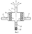
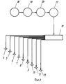
На фиг. 1 показана схема устройства для впуска воздуха; на фиг.2 - схема динамики процессов, происходящих при работе устройства; на фиг.3 - принципиальная схема работы устройства. In FIG. 1 shows a diagram of an air intake device; figure 2 is a diagram of the dynamics of processes occurring during operation of the device; figure 3 is a schematic diagram of the operation of the device.
Устройство содержит воздухоочиститель 1, воздухозаборный патрубок 2 и систему четвертьволновых резонаторов, которая выполнена в виде воздуховода 3, подключенного к полости воздухоочистителя 1 и снабженного регуляторами 4. ..12 его длины. В воздухоочистителе 1 выполнено выходное окно 13 и установлен фильтрующий элемент 14. The device comprises an
Регуляторы 4...12 кинематически связаны с исполнительным механизмом 15 привода 16, который управляется бортовым компьютером, который отслеживает параметры одной из систем (например, системы зажигания 17) через коммутатор 18 импульсов зажигания и микропроцессор 19. Регуляторы 4...12 могут быть выполнены в виде поворотных заслонок, золотников и пр., полностью перекрывающих сечение воздуховода 3 в крайних своих положениях, чем достигается образование определенным образом настроенного четвертьволнового тупикового резонатора, подключенного к полости воздухоочистителя 1. Привод 16 может быть выполнен в виде серво- или шагового двигателя. Воздуховод 3 может быть выполнен в виде замкнутой на корпусе воздухоочистителя 12 петли, при этом регулятор-заслонка 6 расположена на равных расстояниях от точек"А" и "Б" подключения петли к полости воздухоочистителя 1. Схематично показана впускная труба 20 двигателя и один из его поршней 21. The
Устройство работает следующим образом. The device operates as follows.
Возвратно-поступательное перемещение поршня 21 создает во впускной трубе 20 колебания газа, которые через выходное окно 13, передаются в полость воздухоочистителя 1. За счет этих колебаний газ в камере воздухоочистителя периодически сжимается, плотность его повышается и количество газа в объеме камеры воздухоочистителя 1 увеличивается. При этом часть газа, вошедшая в полость воздухоочистителя, расходуется на увеличение количества газа в его камере, а часть поступает в воздухозаборный патрубок 2. Переменное поступление газа в патрубок 2 создает в нем колебания скорости газа. Эти колебания вызывают излучение звука (показано стрелками) выходным срезом патрубка 2 в окружающую среду. При подключении к полости воздухоочистителя 1 замкнутого участка воздуховода (тупикового резонатора) 3, длина которого соответствует 1/4 длины волны колебаний возбуждаемого (излучаемого) в патрубке 2 звука, в полости резонатора возникают резонансные колебания. Эти колебания сопровождаются сильным сжатием газа в резонаторе и усиленным отсосом газа из камеры воздухоочистителя 1. При этом количество пульсирующего газа, поступающего в воздухозаборный патрубок 2, значительно уменьшается и соответственно уменьшается излучение звука выходным срезом воздухозаборного патрубка 2 в окружающую среду. The reciprocating movement of the
В общем виде длина регулируемого участка воздуховода 3 (тупикового резонатора) определяется по формуле
l = ![]()
f4 - частота импульса, с-1.In general, the length of the adjustable section of the duct 3 (dead end resonator) is determined by the formula
l = ![]()
f 4 - pulse frequency, s -1 .
Здесь частота импульса
fи= ![]()
i - число цилиндров;
τ - коэффициент тактности (τ = 2 или для 4-х тактных ДВС и τ = 1 для 2-х тактных ДВС)
После подставки (2) в (1) получают
l = ![]()
Из формулы (3) видно, что для различных оборотов n необходимо устанавливать определенную длину регулируемого участка воздуховода. Число оборотов двигателя заложено в память бортового компьютера который отслеживает их в одной из систем, например отслеживает число импульсов зажигания, пропорциональное числу оборотов двигателя, и при достижении данного числа оборотов двигателя дает соответствующую команду исполнительному механизму 15 привода 16, включая определенным образом те или иные четвертьволновые резонаторы, образованные в воздуховоде 3 регуляторами 4-12, выполненными в виде заслонок, золотников, клапанов и т.п.Here is the pulse frequency
f and = ![]()
i is the number of cylinders;
τ is the tact factor (τ = 2 or for 4-stroke ICEs and τ = 1 for 2-stroke ICE)
After the stand (2) in (1) receive
l = ![]()
From formula (3) it is seen that for various revolutions n it is necessary to set a certain length of the adjustable section of the duct. The engine speed is stored in the memory of the on-board computer, which tracks them in one of the systems, for example, tracks the number of ignition pulses proportional to the engine speed, and when this engine speed is reached, it gives the corresponding command to the actuator 15 of the
Таким образом, число применяемых регуляторов 4-12 достигается, исходя из достижения необходимого эффекта улучшения шума в заданном скоростном диапазоне работы двигателя. Thus, the number of applied regulators 4-12 is achieved on the basis of achieving the necessary effect of improving noise in a given speed range of the engine.
Данное устройство представлено со сдвоенными, одинаково настроенными четвертьволновыми тупиковыми резонаторами, что делает его более эффективным за счет осуществления отсоса в резонаторы из камеры воздухоочистителя 1 с двух ее противоположных сторон и увеличения производительности отсоса. В этом случае на режиме, близком к режиму максимального крутящего момента, закрыта заслонка (регулятор) 8, которая находится в центре воздуховода 3 между точками "А" и "Б". Этот режим, во-первых, характеризуется повышенным шумообразованием на впуске (режимы максимального коэффициента наполнения двигателя), а также необходимостью обеспечения максимальных значений эффективного момента двигателя и минимального удельного расхода топлива. В связи с этим очень важно "успокоить" пульсации газа в камере воздухоочистителя 1 и тем самым увеличить объемный расход всасываемого в двигатель воздуха (вследствие уменьшения гидросопротивлений процесса со сглаженными пульсациями) и уменьшить возбуждение воздушного столба, заключенного в воздухозаборном патрубке 2 и т.о. излучаемого шума его свободным срезом в окружающую среду. This device is presented with dual, equally tuned quarter-wave dead-end resonators, which makes it more efficient due to the exhaustion into the resonators from the chamber of the
И именно, начиная с этих режимов, вплоть до максимальных оборотов двигателя, подключаются два параллельных четвертьволновых тупиковых резонаторов, эффективно сглаживающих эти пульсации. При достижении максимальных оборотов по команде компьютера перекрываются регуляторы 4 и 12. And namely, starting from these modes, up to the maximum engine speed, two parallel quarter-wave dead-end resonators are connected, which effectively smooth out these pulsations. When the maximum speed is reached, the
Claims (5)
где τ - коэффициент тактности двигателя (для 2-х тактного двигателя t = 1, для 4-х тактного двигателя t = 2);
i - число цилиндров двигателя;
c - скорость звука, м/с;
n - число оборотов двигателя.1. A DEVICE FOR INLETING AIR INTO THE VEHICLE INTERNAL COMBUSTION ENGINE, comprising an air cleaner, an air intake pipe connected to it, a drive and a quarter-wave resonator system, characterized in that, in order to increase the efficiency of the device in separate sections or throughout the entire speed range of the engine ensuring the suppression of noise emissions into the environment, in it the system of quarter-wave resonators is made in the form of an air duct connected to the cavity of the air purifier and equipped with at least two regulators of its length, the length of the adjustable sections of the duct is determined from the expression
where τ is the engine cycle coefficient (for a 2-stroke engine t = 1, for a 4-stroke engine t = 2);
i is the number of engine cylinders;
c is the speed of sound, m / s;
n is the engine speed.
Priority Applications (1)
| Application Number | Priority Date | Filing Date | Title |
|---|---|---|---|
| SU4943073 RU2026503C1 (en) | 1991-06-06 | 1991-06-06 | Device for air induction into internal combustion engine |
Applications Claiming Priority (1)
| Application Number | Priority Date | Filing Date | Title |
|---|---|---|---|
| SU4943073 RU2026503C1 (en) | 1991-06-06 | 1991-06-06 | Device for air induction into internal combustion engine |
Publications (1)
| Publication Number | Publication Date |
|---|---|
| RU2026503C1 true RU2026503C1 (en) | 1995-01-09 |
Family
ID=21578081
Family Applications (1)
| Application Number | Title | Priority Date | Filing Date |
|---|---|---|---|
| SU4943073 RU2026503C1 (en) | 1991-06-06 | 1991-06-06 | Device for air induction into internal combustion engine |
Country Status (1)
| Country | Link |
|---|---|
| RU (1) | RU2026503C1 (en) |
-
1991
- 1991-06-06 RU SU4943073 patent/RU2026503C1/en active
Non-Patent Citations (1)
| Title |
|---|
| Заявка ЕПВ N 0091038, кл. F 02M 35/12, 1983. * |
Similar Documents
| Publication | Publication Date | Title |
|---|---|---|
| US8936133B2 (en) | Four cycle internal combustion engine exhaust | |
| RU2026503C1 (en) | Device for air induction into internal combustion engine | |
| ATE67010T1 (en) | PISTON ENGINE WITH INCREASED DELIVERY RATE THROUGH FRESH GAS RESONANCE VIBRATIONS. | |
| JPH04132843A (en) | Fuel injection controller of two-cycle engine | |
| RU2057965C1 (en) | Fuel supply system for power plant | |
| USRE33978E (en) | Air-cooled overhead-valve engine | |
| SU498407A1 (en) | Resonant supercharging system for internal combustion engine | |
| US6202409B1 (en) | Acoustically-enhanced intake/exhaust system and method for internal combustion engines | |
| EP1253312B1 (en) | Low-noise integrated air-filtering device | |
| JPH04303124A (en) | Intake device for engine with mechanical supercharger | |
| RU232031U1 (en) | Automatic noise reduction device for exhaust systems of internal combustion engines | |
| JPH0380964B2 (en) | ||
| JPH1073062A (en) | Fuel system and fuel pump | |
| US11168631B2 (en) | Method and device for controlling compression ignition engine | |
| JP6591797B2 (en) | Internal combustion engine | |
| WO2026022622A1 (en) | An internal combustion engine with a resonator combined with the intake pipe | |
| KR200328087Y1 (en) | Noise Reduce Apparatus of Diesel Engine | |
| JPS59105959A (en) | Resonator | |
| RU2268374C2 (en) | Exhaust silencer for internal combustion engine | |
| JPH10205401A (en) | Intake device with resonator | |
| JP6591798B2 (en) | Internal combustion engine | |
| KR19980016744A (en) | Intake noise reduction device of car | |
| JP6512478B2 (en) | Internal combustion engine | |
| JPS6267224A (en) | Air intake device for internal combustion engine | |
| JPS5985414A (en) | Exhaust noise arrester for internal-combustion engine for car |