RU2024977C1 - Equipment for thermal processing of twisted magnetic circuits - Google Patents
Equipment for thermal processing of twisted magnetic circuits Download PDFInfo
- Publication number
- RU2024977C1 RU2024977C1 SU5036226A RU2024977C1 RU 2024977 C1 RU2024977 C1 RU 2024977C1 SU 5036226 A SU5036226 A SU 5036226A RU 2024977 C1 RU2024977 C1 RU 2024977C1
- Authority
- RU
- Russia
- Prior art keywords
- magnetic
- magnetic field
- unloading
- magnetic circuits
- heating
- Prior art date
Links
- 238000010438 heat treatment Methods 0.000 claims abstract description 29
- 230000015572 biosynthetic process Effects 0.000 claims description 3
- 230000000694 effects Effects 0.000 abstract 1
- 238000004870 electrical engineering Methods 0.000 abstract 1
- 239000000126 substance Substances 0.000 abstract 1
- 239000011162 core material Substances 0.000 description 32
- 238000000137 annealing Methods 0.000 description 3
- 239000000463 material Substances 0.000 description 3
- 238000000034 method Methods 0.000 description 2
- 239000004020 conductor Substances 0.000 description 1
- 238000001816 cooling Methods 0.000 description 1
- 238000004519 manufacturing process Methods 0.000 description 1
- 239000002574 poison Substances 0.000 description 1
- 231100000614 poison Toxicity 0.000 description 1
- XLYOFNOQVPJJNP-UHFFFAOYSA-N water Substances O XLYOFNOQVPJJNP-UHFFFAOYSA-N 0.000 description 1
Images
Landscapes
- Heat Treatments In General, Especially Conveying And Cooling (AREA)
Abstract
Description
Изобретение относится к технологическому оборудованию для изготовления витых ленточных магнитопроводов и может быть использовано в радио- и электротехнической промышленности. The invention relates to technological equipment for the manufacture of twisted tape magnetic circuits and can be used in the radio and electrical industries.
Известно устройство для термообработки витых ленточных магнитопроводов, содержащее тоннельную печь с направляющими элементами и нагревателями, механизм разгрузки, загрузочные лотки с толкателями, расположенные перпендикулярно направляющим элементам печи, и накопитель магнитопроводов, выполненный в виде четырех лотков. Каждый из лотков снабжен кареткой и заслонкой, выполненной в виде Г-образного поворотного рычага [1]. A device for heat treatment of twisted tape magnetic circuits, containing a tunnel furnace with guide elements and heaters, an unloading mechanism, loading trays with pushers located perpendicular to the guide elements of the furnace, and a magnetic circuit drive made in the form of four trays. Each of the trays is equipped with a carriage and a shutter made in the form of a L-shaped rotary lever [1].
Заготовки вручную загружают в накопительные лотки при отведенных толкающих каретках. Затем толкающими каретками перемещают наборы заготовок в лотках до упора в направляющие элементы. Толкатели заталкивают заготовки в направляющие элементы тоннельной печи и одновременно очередные заготовки подаются из накопительных в загрузочные лотки. Заготовки, прошедшие через печь, сталкиваются с направляющих элементов по разгрузочному лотку в приемную тару одновременно с загрузкой очередных заготовок в печь. The blanks are manually loaded into storage trays with the pushing carriages allotted. Then, pushing carriages move sets of blanks in trays all the way into the guide elements. Pushers push the workpieces into the guide elements of the tunnel kiln and at the same time the next workpieces are fed from the storage to the loading trays. The workpieces that have passed through the furnace collide with the guide elements along the discharge tray in the receiving container while loading the next workpieces into the furnace.
Недостаток устройства в низкой производительности, поскольку разогрев заготовок до заданной температуры и их выдержка производятся в одной и той же камере тоннельной печи последовательно по времени, что удлиняет цикл термической обработки. The disadvantage of the device is low productivity, since preforms are heated to a predetermined temperature and held for a time in the same chamber of the tunnel kiln, which lengthens the heat treatment cycle.
Известно также более производительное устройство для термообработки и формирования витых ленточных магнитопроводов, содержащее накопитель, являющийся загрузочной площадкой для обрабатываемых магнитопроводов, тоннельную печь, имеющую камеру нагрева и камеру выдержки, направляющие элементы, расположенные параллельно камерам тоннельной печи, механизм перемещения обрабатываемых магнитопроводов через камеры тоннельной печи и разгрузочный лоток, установленный на позиции разгрузки обработанных магнитопроводов. На выходе из камеры выдержки установлен узел формования магнитопроводов [2]. Also known is a more productive device for heat treatment and the formation of twisted tape magnetic circuits, containing a drive that is a loading platform for the processed magnetic circuits, a tunnel furnace having a heating chamber and a holding chamber, guide elements located parallel to the chambers of the tunnel furnace, a mechanism for moving the processed magnetic circuits through the chambers of the tunnel furnace and an unloading tray mounted at the unloading position of the processed magnetic cores. At the exit from the exposure chamber, a magnetic core forming unit [2] is installed.
В камере нагрева производится разогрев магнитопроводов до температуры отжига, а в камере выдержки одновременно осуществляется отжиг магнитопроводов при заданной температуре. После прохождения камер разогрева и выдержки магнитопровод обжимают клиноплунжерным механизмом и сталкивают на разгрузочный лоток. In the heating chamber, the magnetic cores are heated to the annealing temperature, and in the holding chamber, the magnetic cores are annealed at a given temperature. After passing through the heating and holding chambers, the magnetic circuit is crimped by a clinoplunger mechanism and pushed onto the discharge tray.
Устройство для термообработки и формования витых ленточных магнитопроводов обеспечивает повышенную в сравнении с вышеописанным устройством производительность, поскольку разогрев и отжиг магнитопроводов производятся одновременно в разных камерах. По технической сущности и достигаемому результату оно является наиболее близким к заявляемому, вследствие чего принято за прототип. A device for heat treatment and forming of twisted tape magnetic circuits provides increased productivity in comparison with the above-described device, since magnetic cores are heated and annealed simultaneously in different chambers. According to the technical nature and the achieved result, it is the closest to the claimed, as a result of which it is taken as a prototype.
Недостаток устройства, принятого за прототип, состоит в том, что оно не обеспечивает высокого качества обработки магнитопроводов и высокой производительности. Это объясняется тем, что магнитопроводы загружаются в направляющие и перемещаются через камеры разогрева и выдержки только в один ряд непосредственно друг за другом. При продвижении по направляющим толкатели деформируют магнитопроводы, особенно малогабаритные и навитые из тонкой ленты. Кроме того, в процессе отжига магнитная структура материала магнитопровода, состоящая из диполей, нарушается. Диполи, хаотично ориентирующиеся в процессе отжига, на позиции разгрузки остаются в том же неориентированном положении, что снижает магнитные свойства магнитопровода, как один из основных показателей, определяющих качество обработки. The disadvantage of the device adopted for the prototype is that it does not provide high quality processing of magnetic cores and high performance. This is because the magnetic cores are loaded into the guides and move through the heating and holding chambers only in one row directly one after another. When moving along the guides, the pushers deform the magnetic cores, especially small-sized and wound from a thin tape. In addition, during the annealing process, the magnetic structure of the material of the magnetic circuit, consisting of dipoles, is violated. Dipoles randomly oriented during the annealing process remain at the unloading position at the unloading position, which reduces the magnetic properties of the magnetic circuit, as one of the main indicators determining the quality of processing.
Целью изобретения является повышение качества обработки и производительности. The aim of the invention is to improve the quality of processing and productivity.
Цель достигается тем, что в устройстве для термообработки витых ленточных магнитопроводов, содержащих загрузочную площадку, камеру нагрева, камеру выдержки, разгрузочную площадку, направляющие параллельные камерам нагрева и выдержки, механизм перемещения, согласно изобретению на направляющих установлены поддоны, имеющие ложементы для укладки магнитопроводов, между камерой выдержки и разгрузочной площадкой установлено средство формирования магнитного поля, охватывающего обрабатываемые магнитопроводы, а разгрузочная площадка связана с загрузочной площадкой посредством механизма возврата поддонов. The goal is achieved by the fact that in the device for heat treatment of twisted tape magnetic circuits containing a loading platform, a heating chamber, a holding chamber, an unloading platform guides parallel to the heating and holding chambers, the moving mechanism, according to the invention, pallets are installed on the guides having lodgements for laying magnetic cores between a holding chamber and an unloading platform have a means of forming a magnetic field covering the magnetic circuits being processed, and the unloading platform is connected on with a loading platform by means of a pallet return mechanism.
Кроме того, для расширения функциональных возможностей средство формирования магнитного поля выполнено в виде съемных приставок и содержит приставку продольного магнитного поля и приставку поперечного магнитного поля. In addition, to expand the functionality of the magnetic field forming means is made in the form of removable consoles and contains a longitudinal magnetic field prefix and a transverse magnetic field prefix.
Приставка продольного магнитного поля имеет электропроводные стержни диаметром менее внутреннего диаметра магнитопровода, закрепленные на держателе с возможностью подключения к источнику тока, при этом держатель скреплен с механизмом вертикального перемещения, в ложементах поддона выполнены отверстия для прохода стержней, а под держателем установлены клеммы на расстояниях друг от друга, равных расстояниям между стержнями. The prefix of the longitudinal magnetic field has conductive rods with a diameter less than the inner diameter of the magnetic circuit, mounted on the holder with the possibility of connecting to a current source, while the holder is fastened with a vertical movement mechanism, holes for the passage of the rods are made in the tray lodgements, and terminals are installed under the holder at distances from other equal distances between the rods.
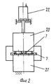
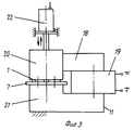
Приставка поперечного магнитного поля содержит электромагнит, имеющий неподвижный и подвижный башмаки, установленные с возможностью размещения между ними поддона с обрабатываемыми магнитопроводами, при этом подвижный башмак прикреплен к механизму возвратно-поступательного перемещения в направлении неподвижного башмака. The prefix of the transverse magnetic field contains an electromagnet having fixed and movable shoes installed with the possibility of placing between them a pallet with processed magnetic circuits, while the movable shoe is attached to the reciprocating movement mechanism in the direction of the fixed shoe.
Камеры нагрева и выдержки выполнены разъемными и имеют подвижные части, скрепленные с механизмом перемещения в направлении соответствующих неподвижных частей. The heating and holding chambers are detachable and have movable parts fastened with a movement mechanism in the direction of the respective stationary parts.
Наличие поддонов с ложементами предотвращает деформацию магнитопроводов при их продвижении вдоль направляющих через камеры нагрева и выдержки до разгрузочной площадки, а также обеспечивает возможность многорядного размещения магнитопроводов в камерах нагрева и выдержки, что увеличивает производительность устройства. The presence of pallets with lodgements prevents the deformation of the magnetic cores as they move along the guides through the heating and holding chambers to the discharge site, and also provides the possibility of multi-row placement of magnetic cores in the heating and holding chambers, which increases the productivity of the device.
Наличие средства формирования магнитного поля, охватывающего обрабатываемые магнитопроводы, позволяет ориентировать диполи материала магнитопровода в нужном направлении, что повышает качество обработки. The presence of a magnetic field generating means covering the magnetic circuits being processed allows orientation of the dipoles of the magnetic core material in the desired direction, which improves the quality of processing.
Благодаря тому, что средство формирования магнитного поля расположено между камерой выдержки и разгрузочной площадкой, обеспечен экономичный режим обработки магнитопроводов в магнитном поле, когда для ориентации диполей в разогретом магнитопроводе, только что вышедшем из камеры выдержки, достаточно относительно низкой напряженности, а при остывании магнитопроводов к концу обработки в магнитном поле улучшается фиксация диполей в заданном направлении. Due to the fact that the magnetic field generating means is located between the exposure chamber and the unloading platform, an economical mode of processing the magnetic cores in the magnetic field is provided, when the dipoles in the heated magnetic circuit that has just emerged from the exposure chamber have a relatively low voltage, and when cooling the magnetic cores, At the end of processing in a magnetic field, the fixation of dipoles in a given direction is improved.
Наличие механизма возврата поддонов обеспечивает возможность автоматического перемещения пустых поддонов от разгрузочной к загрузочной площадке. The presence of a pallet return mechanism provides the ability to automatically move empty pallets from the unloading to the loading area.
Выполнением средства формирования магнитного поля в виде съемных приставок обеспечена возможность получения магнитопроводов с разными магнитными характеристиками, что расширяет номенклатуру выпускаемой продукции. В частности, наличие приставки продольного магнитного поля позволяет получать магнитопроводы с прямоугольной петлей Гистерезиса, использующиеся в запоминающих и переключающих устройствах. Наличие приставки поперечного магнитного поля позволяет получать магнитопроводы с непрямоугольной петлей Гистерезиса, использующиеся во вторичных источниках питания в импульсных трансформаторах. The implementation of the means of forming a magnetic field in the form of removable consoles provides the possibility of obtaining magnetic cores with different magnetic characteristics, which expands the range of products. In particular, the presence of a longitudinal magnetic field attachment makes it possible to obtain magnetic cores with a rectangular hysteresis loop, which are used in storage and switching devices. The presence of a transverse magnetic field attachment makes it possible to obtain magnetic cores with a non-rectangular hysteresis loop, which are used in secondary power supplies in pulse transformers.
Конкретное конструктивное выполнение приставок продольной и поперечного магнитного поля, изложенное в п.3 и 4 формулы, обеспечивает возможность одновременной групповой обработки магнитопроводов в магнитном поле в автоматическом режиме, что повышает производительность устройства. The specific constructive implementation of the prefixes of the longitudinal and transverse magnetic fields set forth in
Выполнением камер нагрева и выдержки разъемными, имеющими подвижные части, скрепленные с механизмом перемещения в направлении соответствующих неподвижных частей, уменьшены потери тепла из камер через входные и выходные отверстия для прохода поддонов с магнитопроводами, поскольку после загрузки поддонов в камеры они могут быть плотно закрыты. Это повышает как экономичность, так и производительность устройства. By executing detachable heating and holding chambers having movable parts fastened to the moving mechanism in the direction of the respective stationary parts, heat losses from the chambers through the inlet and outlet openings for the passage of the pallets with magnetic cores are reduced, since after loading the pallets into the chambers they can be tightly closed. This improves both cost-effectiveness and device performance.
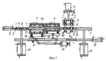
На фиг.1 изображено устройство для термообработки витых ленточных магнитопроводов с приставкой продольного магнитного поля, разрез; на фиг.2 - приставка поперечного магнитного поля, вид спереди; на фиг.3 - то же, вид сбоку. Figure 1 shows a device for heat treatment of twisted tape magnetic circuits with a prefix of a longitudinal magnetic field, section; figure 2 - prefix of the transverse magnetic field, front view; figure 3 is the same side view.
Устройство для термообработки витых ленточных магнитопроводов 1 содержит загрузочную площадку 2, камеру нагрева 3, камеру выдержки 4, разгрузочную площадку 5, а также направляющие 6, параллельные камерам 3 и 4, поддоны 7 с ложементами 8 и для размещения магнитопроводов 1, установленные на направляющих 6, и пневмоцилиндр 9 для перемещения поддонов 7 по направляющим 6. Между камерой выдержки 4 и разгрузочной площадкой 5 установлена одна из двух входящих в комплект устройства приставок 10 или 11. Приставка 10 продольного магнитного поля имеет электропроводные стержни 12 диаметром менее внутреннего диаметра обрабатываемых магнитопроводов 1, закрепленные на держателе 13, прикрепленном к пневмоцилиндру 14. Под держателем 13 установлены клеммы 15 по числу стержней 12. Стержни 12 и клеммы 15 соединены проводниками 16 так, что в нижнем положении держателя 13 образуют непрерывную электрическую цепь, подключенную к источнику тока (не показан). Для прохода стержней через внутренние отверстия магнитопроводов 1 до примыкания к клеммам 15 в ложементах 8 выполнены отверстия 17. Приставка 11 поперечного магнитного поля имеет электромагнит 18 с катушкой 19, подвижным 20 и неподвижным 21 башмаками. Подвижный башмак 20 прикреплен к пневмоцилиндру 22 с возможностью перемещения в направлении неподвижного башмака 21. Загрузочная площадка 2 соединена с пневмоцилиндром 23, а разгрузочная площадка 5 с пневмоцилиндром 24. Под камерами 3 и 4 установлены направляющие 25 для возврата пустых поддонов 7 и пневмоцилиндр 26. Камера нагрева 3 и камера выдержки 4 имеют подвижные плиты 27 и 28 соответственно, установленные через пружины 29 на платформе 30, соединенной посредством параллельных рычагов 31 с пневмоцилиндром 32. В камерах 3 и 4 установлены нагревательные элементы 33. A device for heat treatment of twisted tape
Описываемое устройство работает следующим образом. The described device operates as follows.
На пустой поддон 7, установленный перед камерой нагрева 3 на нагрузочной площадке 2, укладывают магнитопроводы 1, помещая их в ложементы 8. После укладки магнитопроводов 1 пневмоцилиндром 32 опускают платформу 30 вместе с плитами 27 и 28 и пневмоцилиндром 9 передвигают загруженный поддон 7 по направляющим 6 в камеру нагрева 3, а также одновременно передвигают весь ряд поддонов 7, находящихся на направляющих 6. При этом поддон 7, находивщийся в камере нагрева 3, перемещается в камеру выдержки 4. Поддон 7, находившийся в камере выдержки 4, перемещается к приставке 10 или 11. А поддон 7, находившийся в приставке 10 или 11, перемещается на разгрузочную площадку 5. Пневмоцилиндром 32 поднимают платформу 30 и закрывают плитой 27 камеру нагрева 3 и плитой 28 камеру выдержки 4. При этом обе плиты 27 и 28 плотно прижимаются к камерам 3 и 4 пружинами 29. Нагревательные элементы 33 создают в камерах 3 и 4 заданные тепловые режимы. В камере нагрева 3 происходит разогрев магнитопроводов 1 до температуры несколько ниже "точки Кюри" для данного материала магнитопровода, а в камере выдержки происходит выдержка магнитопровода при температуре несколько выше "точки Кюри". On the
В случае использования приставки 10 продольного магнитного поля, после входа поддона 7 с разогретыми магнитопроводами 1 в приставку 10, опускают держатель 13 пневмоцилиндром 14 в крайнее нижнее положение. Стержни 12 проходят через отверстия в магнитопроводах 1 и через отверстия 17 в поддоне 7 до контакта с клеммами 15. При этом образуется замкнутая электрическая цепь из последовательно соединенных стержней 12, подключенная к источнику тока, а все обрабатываемые магнитопроводы 1 оказываются нанизанными на эту электрическую цепь. Ток, проходящий по электрической цепи, создает магнитное поле, направленное вдоль витков магнитопровода 7, т.е. продольное магнитное поле, под действием которого диполи материала ориентируются вдоль ленты магнитопровода. In the case of using the
В случае использования приставки 11 поперечного магнитного поля, после входа поддона 7 с разогретыми магнитопроводами 1 в приставку 11 он ложится на неподвижный башмак 21. Подвижный башмак 20 опускают пневмоцилиндром 22 до соприкосновения с магнитопроводами 1. При пропускании тока через катушку 19 электромагнита 18 между башмаками 20 и 21 возникает магнитное поле, являющееся поперечным относительно ленты, из которой навиты магнитопроводы 1. В процессе обработки магнитопроводов 1 в магнитном поле они остывают и диполи материала магнитопроводов 1 фиксируются в продольном или поперечном направлении в зависимости от используемой приставки 10, 11. In the case of using the
После обработки в магнитном поле поднимают держатель 13 пневмоцилиндром 22, после чего поддон 7 с магнитопроводами 1, продвигаясь по направляющим 6 под действием пнвмоцилиндра 9, поступает на разгрузочную площадку 5, где с поддона снимают обработанные магнитопроводы 1. Разгрузочную площадку 5 с пустым поддоном 7 опускают пневмоцилиндром 24 до совмещения с направляющими 25, на которых расположены в ряд пустые поддоны 7. Загрузочную площадку 2 опускают пневмоцилиндром 23 до совмещения с направляющими 25, после чего пневмоцилиндром 26 перемещают весь ряд пустых поддонов 7 на шаг, равный длине одного поддона 7. При этом поддон 7, находившийся на разгрузочной площадке 5, перемещается на направляющие 25, а поддон 7, находившийся на направляющихся 25, перемещается на загрузочную площадку 5 и затем пневмоцилиндром 23 поднимается вверх на уровень верхних направляющих 6 для загрузки его новыми магнитопроводами 1. Пустая разгрузочная площадка 5 также поднимается вверх пневмоцилиндром 24 на уровень направляющих 6 для приема следующего поддона 7 с обработанными магнитопроводами 1. Далее цикл работы устройства повторяется. При автоматической загрузке и разгрузке магнитопроводов устройство может работать в автоматическом режиме по заданной программе. After processing in a magnetic field, the
Предлагаемое устройство позволяет повысить качество обработки магнитопроводов с обеспечением высоких магнитных свойств, расширить номенклатуру получаемых изделий с разными магнитными характеристиками и повысить произ- водительность. The proposed device allows to improve the quality of processing magnetic cores with high magnetic properties, expand the range of products with different magnetic characteristics and increase productivity.
Claims (5)
Priority Applications (1)
| Application Number | Priority Date | Filing Date | Title |
|---|---|---|---|
| SU5036226 RU2024977C1 (en) | 1992-04-07 | 1992-04-07 | Equipment for thermal processing of twisted magnetic circuits |
Applications Claiming Priority (1)
| Application Number | Priority Date | Filing Date | Title |
|---|---|---|---|
| SU5036226 RU2024977C1 (en) | 1992-04-07 | 1992-04-07 | Equipment for thermal processing of twisted magnetic circuits |
Publications (1)
| Publication Number | Publication Date |
|---|---|
| RU2024977C1 true RU2024977C1 (en) | 1994-12-15 |
Family
ID=21601310
Family Applications (1)
| Application Number | Title | Priority Date | Filing Date |
|---|---|---|---|
| SU5036226 RU2024977C1 (en) | 1992-04-07 | 1992-04-07 | Equipment for thermal processing of twisted magnetic circuits |
Country Status (1)
| Country | Link |
|---|---|
| RU (1) | RU2024977C1 (en) |
Cited By (1)
| Publication number | Priority date | Publication date | Assignee | Title |
|---|---|---|---|---|
| RU2510661C1 (en) * | 2012-11-22 | 2014-04-10 | Владимир Иванович Пудов | Method of magnet core treatment |
-
1992
- 1992-04-07 RU SU5036226 patent/RU2024977C1/en active
Non-Patent Citations (2)
| Title |
|---|
| 1. Авторское свидетельство СССР N 1274013, кл. H 01F 41/02, 1983. * |
| 2. Авторское свидетельство СССР N 1394250, кл. H 01F 41/02, 1985. * |
Cited By (1)
| Publication number | Priority date | Publication date | Assignee | Title |
|---|---|---|---|---|
| RU2510661C1 (en) * | 2012-11-22 | 2014-04-10 | Владимир Иванович Пудов | Method of magnet core treatment |
Similar Documents
| Publication | Publication Date | Title |
|---|---|---|
| RU2024977C1 (en) | Equipment for thermal processing of twisted magnetic circuits | |
| US2714648A (en) | High frequency heating | |
| US20070235662A1 (en) | Flash lamp annealing device | |
| US4649248A (en) | Annealing furnace for annealing magnetic cores in a magnetic field | |
| EP0486247B1 (en) | Method for producing Mn-Zn ferrites | |
| US2794894A (en) | Induction heat-treating apparatus | |
| US20030164372A1 (en) | Device for inductively heating metallic strips | |
| US3051811A (en) | Device for heating workpieces inductively | |
| GB2121260A (en) | Transverse flux induction heater | |
| US5435686A (en) | Bearing race hardening line | |
| US3182168A (en) | High frequency inductor arrangement for heating a number of bar ends in a solenoidal coil | |
| US2714647A (en) | Automatic work handling apparatus | |
| US5310975A (en) | Method and apparatus for the continuous field annealing of amorphous metal transformer cores | |
| US3435170A (en) | Device for heating chemical reagents | |
| US3144364A (en) | Induction annealing of magnetic alloy sheet | |
| US1904214A (en) | Device for high frequency induction heating | |
| US1993022A (en) | Apparatus for heat treating electrodes | |
| KR100195970B1 (en) | Up-loading heat treatment furnace with heat treatment chamber partitioned by heater rod | |
| KR20170125250A (en) | Apparatus for heating material | |
| KR100810472B1 (en) | Inline Curing Method | |
| US6635856B2 (en) | Billet induction heating | |
| CN218512500U (en) | Digital factory-shaped multi-station circular testing equipment for electronic components | |
| US3507967A (en) | Device for heat treatment of wound ribbon magnetic cores | |
| SU1760569A1 (en) | Magnetic core heat treatment device | |
| US3981725A (en) | Process and system for forming finished parts from powder metal |