RU2024973C1 - Process of manufacture of combined superconducting wire - Google Patents
Process of manufacture of combined superconducting wire Download PDFInfo
- Publication number
- RU2024973C1 RU2024973C1 SU925043559A SU5043559A RU2024973C1 RU 2024973 C1 RU2024973 C1 RU 2024973C1 SU 925043559 A SU925043559 A SU 925043559A SU 5043559 A SU5043559 A SU 5043559A RU 2024973 C1 RU2024973 C1 RU 2024973C1
- Authority
- RU
- Russia
- Prior art keywords
- soldered
- elements
- melt
- level
- solder
- Prior art date
Links
- 238000004519 manufacturing process Methods 0.000 title claims abstract description 11
- 238000000034 method Methods 0.000 title description 5
- 229910000679 solder Inorganic materials 0.000 claims abstract description 19
- 239000011159 matrix material Substances 0.000 claims abstract description 18
- 230000002441 reversible effect Effects 0.000 claims abstract description 4
- 239000000155 melt Substances 0.000 claims description 14
- 238000001816 cooling Methods 0.000 claims description 10
- 238000009434 installation Methods 0.000 claims description 4
- 238000005476 soldering Methods 0.000 abstract description 6
- 230000000694 effects Effects 0.000 abstract description 2
- 238000004870 electrical engineering Methods 0.000 abstract description 2
- 239000000126 substance Substances 0.000 abstract 1
- 230000007704 transition Effects 0.000 abstract 1
- 230000015572 biosynthetic process Effects 0.000 description 2
- 230000006835 compression Effects 0.000 description 2
- 238000007906 compression Methods 0.000 description 2
- 239000004020 conductor Substances 0.000 description 2
- 239000007788 liquid Substances 0.000 description 2
- 238000012423 maintenance Methods 0.000 description 2
- 238000007711 solidification Methods 0.000 description 2
- 230000008023 solidification Effects 0.000 description 2
- 150000001875 compounds Chemical class 0.000 description 1
- 238000010276 construction Methods 0.000 description 1
- 230000003247 decreasing effect Effects 0.000 description 1
- 230000032798 delamination Effects 0.000 description 1
- 238000007654 immersion Methods 0.000 description 1
- 239000000463 material Substances 0.000 description 1
- 238000001465 metallisation Methods 0.000 description 1
- 230000000704 physical effect Effects 0.000 description 1
- 230000003014 reinforcing effect Effects 0.000 description 1
- 230000000087 stabilizing effect Effects 0.000 description 1
Images
Classifications
-
- Y—GENERAL TAGGING OF NEW TECHNOLOGICAL DEVELOPMENTS; GENERAL TAGGING OF CROSS-SECTIONAL TECHNOLOGIES SPANNING OVER SEVERAL SECTIONS OF THE IPC; TECHNICAL SUBJECTS COVERED BY FORMER USPC CROSS-REFERENCE ART COLLECTIONS [XRACs] AND DIGESTS
- Y02—TECHNOLOGIES OR APPLICATIONS FOR MITIGATION OR ADAPTATION AGAINST CLIMATE CHANGE
- Y02E—REDUCTION OF GREENHOUSE GAS [GHG] EMISSIONS, RELATED TO ENERGY GENERATION, TRANSMISSION OR DISTRIBUTION
- Y02E40/00—Technologies for an efficient electrical power generation, transmission or distribution
- Y02E40/60—Superconducting electric elements or equipment; Power systems integrating superconducting elements or equipment
Landscapes
- Superconductors And Manufacturing Methods Therefor (AREA)
Abstract
Description
Изобретение относится к горячей металлизации длинномерных изделий и может быть использовано в электротехнике при изготовлении комбинированных проводов, состоящих из нескольких элементов, в том числе сверхпроводящих. The invention relates to the hot metallization of long products and can be used in electrical engineering in the manufacture of combined wires consisting of several elements, including superconducting.
Известен способ изготовления комбинированного сверхпроводящего провода, включающий укладку сверхпроводящего элемента в продольный паз матричного элемента прямоугольной формы, соединение их пайкой легкоплавким припоем и охлаждение [1]. A known method of manufacturing a combined superconducting wire, including laying a superconducting element in a longitudinal groove of a rectangular matrix element, soldering them with fusible solder and cooling [1].
Для большинства длинномерных изделий такой способ не может обеспечить достаточного качества продукции при приемлемой технологической скорости, так как всегда требуется свободное открытое с одной стороны расположение многопроволочного элемента, уложенного в паз матрицы, пропайка и полное заполнение которых крайне затруднены. Используемая схема заполнения и закрепления элементов в пазе исключает возможность селективного и стабильного заполнения его припоем, не обеспечивает стабильного взаимного положения элементов по всей длине, исключения пустот, раковин при охлаждении. For most lengthy products, this method cannot provide sufficient product quality at an acceptable technological speed, since it always requires a free open on one side arrangement of a multi-wire element laid in the groove of the matrix, the soldering and full filling of which are extremely difficult. The used scheme of filling and securing elements in a groove eliminates the possibility of selective and stable filling with solder, does not provide a stable relative position of the elements along the entire length, eliminating voids, sinks during cooling.
Наиболее близким к изобретению является способ изготовления комбинированного сверхпроводящего провода, при котором через расплав припоя раздельно пропускают по меньшей мере один нижний матричный элемент с по меньшей мере одним продольным пазом и впаиваемые или впаиваемые и напаиваемые элементы, полученную заготовку с уложенными в паз впаиваемыми элементами обжимают в канале калибра, расположенном на выходе из расплава, и осуществляют ее локальное охлаждение [2]. Closest to the invention is a method of manufacturing a combined superconducting wire, in which at least one lower matrix element with at least one longitudinal groove is separately passed through the solder melt and the soldered or soldered and soldered elements, the resulting workpiece with the soldered elements laid in the groove, are pressed into the caliber channel located at the outlet of the melt, and carry out its local cooling [2].
Характерной особенностью комбинированных проводов большого сечения (≥50 мм2) является присутствие в конструкции многопроволочных сверхпроводящих токонесущих элементов проводников диаметром ≥0,85 мм, а также прокладочных резистивных, трубчатых охлаждающих, установочных высокопроводящих или упрочняющих элементов с характерными размерами от нескольких до трех десятков миллиметров. Межэлементные и межпроволочные зазоры и допуски существенно превосходят аналогичные параметры малых сечений. Вследствие нежелательного и неконтролируемого нарушения геометрии и других физических свойств впаиваемых элементов обжатие матричных элементов при изготовлении конструкций большого сечения надо поддерживать на уровне, не превышающем 0,5-1%. Последнее не позволяет стабилизировать положение впаиваемых и напаиваемых элементов за счет обжатия на 5-15%, как в прототипе. При угле выхода 15-90о к уровню расплава, отсутствии контролируемой ориентации и задания напряжения элементов относительно друг друга и в особенности относительно нижнего матричного элемента и уровня расплава на участке перед входом в калибр, в канале калибра и после выхода из него до участка охлаждения припой вытекает из межпроволочных и межэлементных зазоров наблюдается каплеобразование, расслаивание элементов после выхода из калибра. Значительный угол выхода провода из расплава исключает также возможность селективного обслуживания, так как позволяет осуществить только грубую регулировку заполнения паза припоем за счет изменения положения калибра относительно уровня расплава.A characteristic feature of combined wires of large cross-section (≥50 mm 2 ) is the presence in the design of multi-wire superconducting current-carrying elements of conductors with a diameter of ≥0.85 mm, as well as gasket resistive, tubular cooling, installation of highly conductive or reinforcing elements with characteristic sizes from several to three tens of millimeters . Interelement and interwire clearances and tolerances significantly exceed the similar parameters of small cross sections. Due to undesirable and uncontrolled violations of the geometry and other physical properties of the soldered elements, the compression of the matrix elements in the manufacture of structures of large cross-section must be maintained at a level not exceeding 0.5-1%. The latter does not allow to stabilize the position of soldered and soldered elements due to compression by 5-15%, as in the prototype. At an angle of 15-90 to the output level of the melt, the absence of controlled orientation and voltage reference elements relative to each other and in particular relative to the lower element of the matrix and the melt level in the area in front of the gauge, gauge channel and after output therefrom to the solder cooling section follows from the interwire and interelement gaps, droplet formation, delamination of the elements after exiting the gauge are observed. A significant angle of exit of the wire from the melt also eliminates the possibility of selective maintenance, since it allows only coarse adjustment of the filling of the groove with solder due to a change in the position of the caliber relative to the level of the melt.
Задачей изобретения является обеспечение возможности изготовления комбинированных проводов сечением 50-1000 мм2 с высокой точностью геометрического расположения элементов по всей длине без нарушения их формы, получения сплошного паяного соединения между элементами провода и селективной подпайки верхнего впаиваемого или напаиваемого элемента за счет высокоточной регулировки уровня заполнения паза припоем.The objective of the invention is to enable the manufacture of combined wires with a cross section of 50-1000 mm 2 with high accuracy of the geometric arrangement of the elements along the entire length without disturbing their shape, to obtain a continuous soldered connection between the wire elements and the selective soldering of the upper soldered or soldered element due to high-precision adjustment of the groove filling level solder.
В способе изготовления комбинированного сверхпроводящего провода, при котором через расплав припоя раздельно пропускают по меньшей мере один нижний матричный элемент, с по меньшей мере одним продольным пазом и впаиваемые или впаиваемые и напаиваемые элементы, полученную заготовку с уложенными в паз впаиваемыми элементами обжимают в канале калибра, расположенном на выходе из расплава, и осуществляют ее локальное охлаждение, укладку впаиваемых элементов осуществляют на участке перед входом в калибр, по меньшей мере один нижний матричный элемент на этом участке пропускают по траектории с отрицательной кривизной, каждый последующий элемент поддерживают в напряженно-растянутом состоянии относительно предыдущего, обеспечивая повышение относительного удлинения каждого из них в пределах обратимой деформации, при этом уровень расплава в канале калибра устанавливают между нижней и верхней точками верхнего впаиваемого или напаиваемого элемента и заготовку выводят из канала калибра под углом 0-5о к уровню расплава.In the method of manufacturing a combined superconducting wire, in which at least one lower matrix element with at least one longitudinal groove and soldered or soldered and soldered elements are separately passed through the solder melt, the resulting workpiece with the soldered elements placed in the groove is crimped in the caliber channel, located at the exit of the melt, and carry out its local cooling, the installation of soldered elements is carried out in the area before entering the caliber, at least one lower matrix the ith element in this section is passed along a path with negative curvature, each subsequent element is maintained in a tensile state relative to the previous one, providing an increase in the relative elongation of each of them within the reversible deformation, while the melt level in the caliber channel is set between the lower and upper points of the upper soldered or soldered element and the workpiece is removed from the channel of the caliber at an angle of 0-5 about the level of the melt.
Способ осуществляют следующим образом. The method is as follows.
Предварительно изготавливают матричный стабилизирующий элемент прямоугольной формы с одним или несколькими пазами на широкой стороне, многопроволочный сверхпроводящий проводник и другие функциональные впаиваемые и напаиваемые элементы. Элементы подвергают совмещенному и/или раздельному флюсованию одним или несколькими составами в зависимости от вида конструкции комбинированного провода и используемых материалов. В ряде случаев осуществляют селективное флюсование части поверхности впаиваемых или напаиваемых элементов. После этого элементы, разделенные в вертикальной и горизонтальной плоскостях, пропускают через расплав припоя, например ПОССу-30-2 или ПОС-61 со скоростью 1,5-10 м/мин. В ряде случаев верхний элемент обслуживают селективно, подводя его нижней стороной к поверхности припоя перед калибром. Перед входом в калибр на участке укладки нижний матричный элемент и в большинстве случаев впаиваемые элементы пропускают в расплаве по траектории с отрицательной кривизной (т.е. с уменьшающимся углом наклона по направлению хода), значение которой наибольшее у нижнего матричного элемента. A rectangular matrix stabilizing element with one or more grooves on the wide side, a multi-wire superconducting conductor, and other functional soldered and soldered elements are pre-fabricated. Elements are subjected to combined and / or separate fluxing with one or more compounds, depending on the type of construction of the combined wire and the materials used. In some cases, selective fluxing of part of the surface of soldered or soldered elements is carried out. After that, the elements, separated in vertical and horizontal planes, are passed through a solder melt, for example, POSSu-30-2 or POS-61 at a speed of 1.5-10 m / min. In some cases, the upper element is served selectively, bringing its lower side to the surface of the solder before the caliber. Before entering the gauge at the laying site, the lower matrix element and, in most cases, the soldered elements are passed in the melt along a path with negative curvature (i.e., with a decreasing angle of inclination in the direction of travel), the value of which is greatest for the lower matrix element.
Верхние впаиваемые или напаиваемые элементы в ряде случаев могут пропускать перед входом в калибр по прямой линии. Необходимость в этом возникает в том случае, когда требования к проводу исключают попадание припоя на боковые и верхнюю поверхности этих элементов. При этом во всех случаях каждый верхний элемент поддерживают в напряженно-растянутом состоянии относительно нижнего при условии повышения их удлинения при переходе от нижнего элемента к верхнему в пределах обратимой деформации. Указанными приемами обеспечивают стабильную взаимную ориентацию элементов провода в процессе укладки до входа в калибр и в канале калибра, устраняют поперечные перемещения элементов в калибре и на участке выравнивания траектории между калибром и участком локального охлаждения, которые приводят к неоднородному заполнению паза припоем и каплеобразованию. In some cases, upper soldered or soldered elements may be passed before entering the caliber in a straight line. The need for this arises when the requirements for the wire exclude solder from entering the side and top surfaces of these elements. Moreover, in all cases, each upper element is supported in a tensile state relative to the lower one, provided that their elongation increases when passing from the lower element to the upper one within the limits of reversible deformation. These methods ensure stable mutual orientation of the wire elements during installation before entering the gauge and in the caliber channel, eliminate lateral movements of elements in the caliber and on the alignment path between the caliber and the local cooling section, which lead to inhomogeneous filling of the groove with solder and droplet formation.
При угле выхода провода из калибра 0-5о к уровню расплава эффект стекания припоя до момента затвердевания незначителен. С учетом поддержания уровня расплава в канале между нижней и верхней точками верхнего впаиваемого или напаиваемого элемента это позволяет регулировать уровень заполнения пазов матричных элементов и обеспечить как полное заполнение межэлементного пространства, так и селективную напайку верхнего из элементов, предотвращая попадание припоя на его верхнюю и боковые стороны. Комбинированное охлаждение осуществляют локально в нескольких местах после выхода провода из калибра. В зависимости от конструкции изделие сначала охлаждают одной или несколькими газожидкостными струями до отвердевания припоя на поверхности, жидкостными струями или частичным погружением в воду, обеспечивая направленную кристаллизацию припоя и охлаждая изделие до 80-120оС и воздушными струями до температуры, близкой к комнатной.When the angle of exit of the wire from the caliber 0-5 about to the level of the melt, the effect of runoff of solder until solidification is negligible. Taking into account the maintenance of the level of the melt in the channel between the lower and upper points of the upper soldered or soldered element, this allows you to adjust the level of filling the grooves of the matrix elements and provide both complete filling of the interelement space and selective soldering of the upper element, preventing solder from entering its upper and lateral sides . Combined cooling is carried out locally in several places after the wire leaves the caliber. Depending on the design of the product is first cooled by one or more gas-liquid jet to solidify the solder on the surface, liquid jets or partial immersion, providing solder directional solidification and cooling the product to 80-120 ° C and the air jets to a temperature close to room temperature.
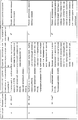
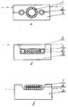
Конкретные условия изготовления сверхпроводящих проводов примерных конструкций, изображенных на чертеже, приведены в таблице. Specific conditions for the manufacture of superconducting wires of exemplary structures shown in the drawing are shown in the table.
Пунктирной линией показано положение уровня припоя в калибре в процессе изготовления проводов. The dashed line shows the position of the solder level in the caliber during the manufacture of the wires.
Конструкция (а) содержит токонесущий сверхпроводящий элемент 1, трубчатый элемент 2, матричный элемент 3. Конструкция (б) включает токонесущий сверхпроводящий элемент 1, трубчатый элемент 2, матричный элемент 3 и напаиваемый высокопроводящий элемент 4. Конструкция (в) содержит токонесущий элемент 1, изолирующую прокладку 2 и матричный элемент 3. Design (a) contains a current-carrying superconducting element 1, a
Как видно из данных таблицы, предлагаемый способ позволяет обеспечить полное и регулируемое заполнение межпроволочного и межэлементного пространства при получении комбинированных проводов большого сечения методом пайки. As can be seen from the table, the proposed method allows for a complete and adjustable filling of the interwire and inter-element space when receiving combined wires of large cross section by soldering.
Claims (1)
Priority Applications (1)
| Application Number | Priority Date | Filing Date | Title |
|---|---|---|---|
| SU925043559A RU2024973C1 (en) | 1992-05-02 | 1992-05-02 | Process of manufacture of combined superconducting wire |
Applications Claiming Priority (1)
| Application Number | Priority Date | Filing Date | Title |
|---|---|---|---|
| SU925043559A RU2024973C1 (en) | 1992-05-02 | 1992-05-02 | Process of manufacture of combined superconducting wire |
Publications (1)
| Publication Number | Publication Date |
|---|---|
| RU2024973C1 true RU2024973C1 (en) | 1994-12-15 |
Family
ID=21604930
Family Applications (1)
| Application Number | Title | Priority Date | Filing Date |
|---|---|---|---|
| SU925043559A RU2024973C1 (en) | 1992-05-02 | 1992-05-02 | Process of manufacture of combined superconducting wire |
Country Status (1)
| Country | Link |
|---|---|
| RU (1) | RU2024973C1 (en) |
-
1992
- 1992-05-02 RU SU925043559A patent/RU2024973C1/en active
Non-Patent Citations (2)
| Title |
|---|
| 1. Заявка Японии N 61-15535, кл. H 01B 13/00, 1986. * |
| 2. Электротехника, N 3, 1991, с.16-19. * |
Similar Documents
| Publication | Publication Date | Title |
|---|---|---|
| US5994659A (en) | Method and apparatus for welding with preheated filler material | |
| DE1596590B1 (en) | Method and apparatus for controlling the temperature of a layer of molten glass on a bath of molten metal | |
| DE10246270A1 (en) | Method and device for producing circuit arrangements | |
| US3286340A (en) | Fabrication of semiconductor units | |
| RU2024973C1 (en) | Process of manufacture of combined superconducting wire | |
| EP1384561B1 (en) | Temperature sensor and heating means for hot runner systems | |
| EP0137888A2 (en) | Device for injection-moulding | |
| EP1506826B1 (en) | Continuous casting mould | |
| US4411534A (en) | Method of continuously measuring the temperature of the surface of a continuously cast strand over its length | |
| DE69818658T2 (en) | METHOD FOR COATING BY MEANS OF ELECTRIC SLAG METHOD | |
| DE2542582A1 (en) | DEVICE FOR ELECTRICALLY CONNECTING A CONTAINER TO A POWER SOURCE | |
| EP0227596B1 (en) | Process and device for controlling the cooling rate of a continuous billet | |
| DE2244039C3 (en) | Methods and apparatus for manufacturing wired glass | |
| DE876695C (en) | Device for the heat treatment of wire or the like. | |
| EP1271565B1 (en) | Capacitance controlling process | |
| DE69909062T2 (en) | DEVICE FOR CASTING METAL | |
| JP2951463B2 (en) | Multi-core insulated wire manufacturing equipment | |
| DE1817124A1 (en) | Method and device for cooling metal melts formed by electroslag remelting, in particular steel melts | |
| JPH0427174B2 (en) | ||
| SU958036A1 (en) | Apparatus for breaking metal spray | |
| SE441907B (en) | PROCEDURE AND DEVICE FOR ELECTRIC LIGHT REAR WELDING OF SEPARATE Separate Parallel Edges from Two Metal Plates | |
| DE1060519B (en) | Device for the production of welded pipes | |
| GB2106701A (en) | Mineral insulated electric cable | |
| EP0063248A1 (en) | Method and apparatus for distributing molten materials, in particular molten mineral materials | |
| JPH06319217A (en) | Earth molding having conductor |