RU2024945C1 - Checking device of document authenticity - Google Patents
Checking device of document authenticity Download PDFInfo
- Publication number
- RU2024945C1 RU2024945C1 SU4875625A RU2024945C1 RU 2024945 C1 RU2024945 C1 RU 2024945C1 SU 4875625 A SU4875625 A SU 4875625A RU 2024945 C1 RU2024945 C1 RU 2024945C1
- Authority
- RU
- Russia
- Prior art keywords
- case
- banknote
- authenticity
- control
- white light
- Prior art date
Links
- 230000005855 radiation Effects 0.000 claims abstract description 13
- 239000011521 glass Substances 0.000 claims abstract description 5
- 230000000007 visual effect Effects 0.000 claims description 2
- 230000000694 effects Effects 0.000 abstract 1
- 230000008092 positive effect Effects 0.000 abstract 1
- 239000000126 substance Substances 0.000 abstract 1
- 239000012634 fragment Substances 0.000 description 3
- 239000000463 material Substances 0.000 description 2
- 238000006243 chemical reaction Methods 0.000 description 1
- 239000000835 fiber Substances 0.000 description 1
- 238000005286 illumination Methods 0.000 description 1
- 238000011179 visual inspection Methods 0.000 description 1
Images
Landscapes
- Inspection Of Paper Currency And Valuable Securities (AREA)
Abstract
Description
Изобретение относится к банковской технике и предназначено для контроля подлинности банкнотов и других ценных бумаг. Устройство также может быть использовано в криминалистике при экспертизе подлинности различных документов. The invention relates to banking equipment and is intended to control the authenticity of banknotes and other securities. The device can also be used in forensics in the examination of the authenticity of various documents.
Целью настоящего изобретения является повышение достоверности контроля подлинности документов, а также повышение удобства эксплуатации, компактности и эргономичности устройства. The aim of the present invention is to increase the reliability of the control of the authenticity of documents, as well as improving the usability, compactness and ergonomics of the device.
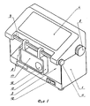
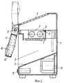
На фиг. 1 представлено устройство, общий вид; на фиг. 2 - поперечное сечение первого варианта устройства; на фиг. 3 - поперечное сечение второго варианта устройства. In FIG. 1 shows a device, a General view; in FIG. 2 is a cross section of a first embodiment of a device; in FIG. 3 is a cross section of a second embodiment of the device.
Устройство (фиг. 1) содержит корпус 1 с нижним столиком 2 и входным отверстием 3. В верхней части корпуса 1 выполнен верхний столик, снабженный светопроницаемым окном 4, изготовленным из диффузнорассеивающего материала. Нижний столик 2 и верхний столик со светопроницаемым окном 4 установлены наклонно, под углом 25о к горизонтали, с понижением в сторону передней части прибора. Угол наклона выбран таким образом, чтобы документ, например банкнот, не соскальзывал с поверхности окна 4 и столика 2 при контроле. Наклон обеспечивает необходимую для эксплуатации эргономичность.The device (Fig. 1) contains a
Внутри корпуса 1 (фиг. 2) установлены источники 5 светового излучения. Источники 5 излучают комбинированное излучение, содержащее белый свет и ультрафиолетовое излучение. Светопроницаемое окно пропускает белый свет поглощает ультрафиолетовое излучение. Диффузнорассеивающий материал окна 4 обеспечивает равномерную яркость по поверхности окна и, соответственно, равномерное освещение белым светом различных участков банкнота, находящегося на светопроницаемом окне 4. Inside the housing 1 (Fig. 2),
В корпусе 1 (фиг. 2) на оси 6 установлен также ультрафиолетовый фильтр 7, имеющий два рабочих положения - горизонтальное и вертикальное, показанное пунктиром. Положение фильтра 7 переключается с помощью маховика 8 (фиг. 1). In the housing 1 (Fig. 2), an ultraviolet filter 7 is also installed on the
Ультрафиолетовый фильтр 7, находясь в вертикальном положении, обеспечивает облучение банкнота, находящегося на нижнем столике, комбинированным излучением. Так как интенсивность флуоресценции банкнотов, вызванная воздействием ультрафиолетовой компоненты комбинированного излучения, существенно меньше интенсивности отраженной от банкнота компоненты белого света, то вертикальное положение фильтра 7 фактически обеспечивает контроль банкнота, находящегося на нижнем столике 2, в отраженном белом свете. The ultraviolet filter 7, being in a vertical position, provides irradiation of a banknote located on the lower table with combined radiation. Since the fluorescence intensity of banknotes caused by the ultraviolet component of the combined radiation is substantially lower than the intensity of the white light component reflected from the banknote, the vertical position of the filter 7 actually provides control of the banknote located on the lower table 2 in reflected white light.
На горизонтальной оси 9 (фиг. 2) установлена бифокальная лупа 10. Лупа 10 допускает поворот вокруг оси 9 на угол от 0 до 180о, обеспечивая удобное позиционирование для визуального контроля банкнотов, находящихся как на нижнем столике 2, так и на светопроницаемом окне 4. Угол поворота лупы 10 в диапазоне от 0 до 180о фиксируется маховиком 11 (фиг. 1). Кроме того, лупа 10 имеет возможность перемещения вдоль оси 9 в пределах светопроницаемого окна 4.The horizontal axis 9 (FIG. 2) is mounted
Внутри корпуса 1, под нижним столиком 2, размещены сетевой выключатель 12 и пускорегулирующий аппарат 13 для включения источников излучения. Inside the
Во втором варианте устройства (фиг. 3) в корпусе установлены источник 14 белого света и источник 15 ультрафиолетового излучения. Ультрафиолетовый фильтр из конструкции исключен. Коммутация типа используемого излучения осуществляется электрически, путем переключения источников излучения с помощью дополнительного выключателя, установленного под нижним столиком 2 (не показан). In the second embodiment of the device (Fig. 3), a white light source 14 and an ultraviolet radiation source 15 are installed in the housing. The ultraviolet filter is excluded from the design. Switching the type of radiation used is carried out electrically, by switching the radiation sources using an additional switch mounted under the lower table 2 (not shown).
Работает устройство следующим образом. The device operates as follows.
Сетевым выключателем 12 устройство (фиг. 2) включают в питающую сеть. С помощью маховика 11 бифокальную лупу 10 устанавливают в верхнее положение, удобное для наблюдения банкнота. Контролируемый банкнот помещают на светопроницаемое окно 4. Через лупу 10 контролируют состояние водяных знаков, рисунка и бумаги в проходящем белом свете. Мелкие фрагменты банкнота наблюдают через короткофокусную зону 16 бифокальной лупы 10, при этом они видимы со значительным увеличением. Обзор всего банкнота осуществляют через длиннофокусную зону 17 бифокальной лупы 10. Оператор манипулирует положением банкнота относительно фокальных плоскостей лупы для достижения различного видимого увеличения, обеспечивая этим оптимальный контроль банкнота в проходящем белом свете. The
Затем контролируемый банкнот через широкую щель 3 помещают на нижний столик 2. С помощью маховика 8 ультрафиолетовый фильтр 7 устанавливают в вертикальное положение. С помощью маховика 11 бифокальную лупу 10 устанавливают в нижнее положение, удобное для наблюдения банкнота. Через лупу 10 контролируют состояние водяных знаков, рисунка и бумаги в отраженном белом свете. Оператор манипулирует положением банкнота относительно фокальных плоскостей лупы для достижения различного видимого увеличения изображения, обеспечивая этим оптимальный контроль банкнота или его фрагментов в отраженном белом свете. Изменяя угол наклона банкнота относительно линии наблюдения, оператор осуществляет контроль банкнота в скользящих лучах. Таким образом, контроль в скользящих лучах с малыми углами падения на данном устройстве осуществляют в одной зоне нижнего столика 2. Then the controlled banknote through a
Далее с помощью маховика 8 ультрафиолетовый фильтр 7 устанавливают в горизонтальное положение. Через лупу 10 контролируют флуоресценцию банкнота, возбуждаемую под воздействием ультрафиолетового излучения. Оператор манипулирует положением банкнота относительно фокальных плоскостей лупы для достижения различного видимого увеличения изображения, обеспечивая этим оптимальный контроль флуоресцирующих зон банкнота, включая защитные волокна. Next, using the flywheel 8, the ultraviolet filter 7 is installed in a horizontal position. Through a
На основании сравнения результатов наблюдения контролируемого банкнота со зрительным стандартом подлинного банкнота оператор судит о подлинности контролируемого банкнота. Based on a comparison of the observation results of the controlled banknote with the visual standard of the genuine banknote, the operator judges the authenticity of the controlled banknote.
Работа устройства по второму варианту (фиг. 3) аналогична работе устройства по первому варианту. При этом ультрафиолетовый контроль банкнота, находящегося на нижнем столике 2, возможен только при выключенном источнике 14 белого света. The operation of the device according to the second embodiment (Fig. 3) is similar to the operation of the device according to the first embodiment. At the same time, ultraviolet control of the banknote located on the lower table 2 is possible only when the white light source 14 is turned off.
Таким образом, предлагаемое устройство позволяет проводить комплексный контроль подлинности документов, так как при контроле исследуются различные признаки подлинности как в проходящем и отраженном белом свете, так и при ультрафиолетовом облучении. Бифокальная лупа в верхнем и нижнем положении, формируя увеличенное изображение банкнота или его фрагментов, обеспечивает повышение достоверности контроля. Наличие наклона нижнего столика и светопроницаемого окна, а также отверстия для ввода банкнота на нижний столик обеспечивают удобство эксплуатации прибора и его эргономичность. Наличие одной зоны контроля на нижнем столике обеспечивает компактность предлагаемого устройства. Использование прибора в классах пересчета позволяет значительно увеличить качество экспертизы и соответственно уменьшить затраты на экспертизу денежных билетов. Thus, the proposed device allows for comprehensive control of the authenticity of documents, since the control examines various signs of authenticity in transmitted and reflected white light, as well as under ultraviolet radiation. Bifocal magnifier in the upper and lower position, forming an enlarged image of a banknote or its fragments, provides an increase in the reliability of control. The presence of a tilt of the lower table and a translucent window, as well as holes for entering a banknote on the lower table, ensure the ease of use of the device and its ergonomics. The presence of one control zone on the lower table ensures the compactness of the proposed device. Using the device in conversion classes can significantly increase the quality of examination and, accordingly, reduce the cost of examination of cash tickets.
Claims (1)
Priority Applications (1)
| Application Number | Priority Date | Filing Date | Title |
|---|---|---|---|
| SU4875625 RU2024945C1 (en) | 1990-10-17 | 1990-10-17 | Checking device of document authenticity |
Applications Claiming Priority (1)
| Application Number | Priority Date | Filing Date | Title |
|---|---|---|---|
| SU4875625 RU2024945C1 (en) | 1990-10-17 | 1990-10-17 | Checking device of document authenticity |
Publications (1)
| Publication Number | Publication Date |
|---|---|
| RU2024945C1 true RU2024945C1 (en) | 1994-12-15 |
Family
ID=21541352
Family Applications (1)
| Application Number | Title | Priority Date | Filing Date |
|---|---|---|---|
| SU4875625 RU2024945C1 (en) | 1990-10-17 | 1990-10-17 | Checking device of document authenticity |
Country Status (1)
| Country | Link |
|---|---|
| RU (1) | RU2024945C1 (en) |
Cited By (5)
| Publication number | Priority date | Publication date | Assignee | Title |
|---|---|---|---|---|
| WO1996030878A1 (en) * | 1995-03-31 | 1996-10-03 | Scientific Production Enterprise 'regula' | Device for validating bank notes and other similar items |
| RU2124229C1 (en) * | 1995-03-14 | 1998-12-27 | Гусинский Валерий Залманович | Bank-note counter |
| RU2224292C2 (en) * | 1999-03-20 | 2004-02-20 | Михаил Павлович Журавченко | Process of manufacture of printed matter to conduct drawing |
| RU2723409C1 (en) * | 2019-08-23 | 2020-06-11 | Закрытое акционерное общество "ЛЕТА" | Personal identity documents scanner |
| RU2803109C1 (en) * | 2022-10-21 | 2023-09-06 | Общество с ограниченной ответственностью "СМАРТ ЭНДЖИНС СЕРВИС" | Automatic scanner with a multispectral system for verifying the authenticity of passport and visa documents |
-
1990
- 1990-10-17 RU SU4875625 patent/RU2024945C1/en active
Non-Patent Citations (2)
| Title |
|---|
| 1. Заявка Франции N 2410855 кл. G 07D 7/00, опубл. 1979. * |
| 2. Патент СССР N 1367872 кл. G 07D 7/00, опубл. 1984. * |
Cited By (5)
| Publication number | Priority date | Publication date | Assignee | Title |
|---|---|---|---|---|
| RU2124229C1 (en) * | 1995-03-14 | 1998-12-27 | Гусинский Валерий Залманович | Bank-note counter |
| WO1996030878A1 (en) * | 1995-03-31 | 1996-10-03 | Scientific Production Enterprise 'regula' | Device for validating bank notes and other similar items |
| RU2224292C2 (en) * | 1999-03-20 | 2004-02-20 | Михаил Павлович Журавченко | Process of manufacture of printed matter to conduct drawing |
| RU2723409C1 (en) * | 2019-08-23 | 2020-06-11 | Закрытое акционерное общество "ЛЕТА" | Personal identity documents scanner |
| RU2803109C1 (en) * | 2022-10-21 | 2023-09-06 | Общество с ограниченной ответственностью "СМАРТ ЭНДЖИНС СЕРВИС" | Automatic scanner with a multispectral system for verifying the authenticity of passport and visa documents |
Similar Documents
| Publication | Publication Date | Title |
|---|---|---|
| JP3051207B2 (en) | Apparatus and method for inspecting documents | |
| US6714288B2 (en) | Counterfeit detection apparatus | |
| WO1994016412B1 (en) | Detection of counterfeit objects | |
| CN104737000B (en) | Device for analysis system, the analysis system with the device and the method for using the device | |
| NO338185B1 (en) | fluorometer | |
| US4634872A (en) | Process for checking the authenticity of documents as well as apparatus therefor | |
| RU2024945C1 (en) | Checking device of document authenticity | |
| CN102539432A (en) | Optical measuring device | |
| GB2334574A (en) | Apparatus for the detection of counterfeit items by their fluorescence | |
| DE102009023431B4 (en) | Device for optically checking documents | |
| JP2006258808A (en) | Portable type fluorescence detector fitted to protection of eye | |
| EP2419886B1 (en) | Verification system and method for verifying diffractive and/or reflective security features of security documents | |
| US20050211914A1 (en) | Device for verifying security features | |
| AU2003209915B2 (en) | Device for checking security elements | |
| JP2001201693A (en) | Illumination system and illumination method for high resolution light microscope | |
| RU2237282C2 (en) | Device for reading graphic and text information | |
| CN110031409B (en) | Multi-spectral anti-counterfeiting feature inspection equipment and inspection method | |
| WO1992015484A1 (en) | An illuminator, especially a runway approach flashlight | |
| JPH05232040A (en) | External appearance inspecting floodlight device | |
| RU15040U1 (en) | DEVICE FOR CONTROL OF AUTHENTICITY OF BANKNOTES | |
| DK9300343U3 (en) | Banknote testing apparatus | |
| US6995903B1 (en) | Microscope, a method for manufacturing a microscope and a method for operating a microscope | |
| CN222394394U (en) | New LED black mirror purple light desk lamp | |
| JP3253942B2 (en) | Light inspection device for visual inspection | |
| JP2003510638A (en) | Apparatus and method for wavelength separation of light |