RU2024920C1 - Device for time count - Google Patents
Device for time count Download PDFInfo
- Publication number
- RU2024920C1 RU2024920C1 SU4855405A RU2024920C1 RU 2024920 C1 RU2024920 C1 RU 2024920C1 SU 4855405 A SU4855405 A SU 4855405A RU 2024920 C1 RU2024920 C1 RU 2024920C1
- Authority
- RU
- Russia
- Prior art keywords
- inputs
- group
- input
- output
- outputs
- Prior art date
Links
- 230000015654 memory Effects 0.000 claims abstract description 71
- 238000012546 transfer Methods 0.000 claims abstract description 33
- 230000007274 generation of a signal involved in cell-cell signaling Effects 0.000 claims description 4
- 230000002457 bidirectional effect Effects 0.000 abstract description 6
- 230000009467 reduction Effects 0.000 abstract description 3
- 230000000694 effects Effects 0.000 abstract 2
- 238000004393 prognosis Methods 0.000 abstract 2
- 238000010606 normalization Methods 0.000 abstract 1
- 239000000126 substance Substances 0.000 abstract 1
- 230000009471 action Effects 0.000 description 30
- 238000000034 method Methods 0.000 description 28
- 101100490566 Arabidopsis thaliana ADR2 gene Proteins 0.000 description 11
- 101100269260 Saccharomyces cerevisiae (strain ATCC 204508 / S288c) ADH2 gene Proteins 0.000 description 11
- 101150022075 ADR1 gene Proteins 0.000 description 10
- 238000010586 diagram Methods 0.000 description 9
- 230000015572 biosynthetic process Effects 0.000 description 8
- 230000005540 biological transmission Effects 0.000 description 7
- 230000004048 modification Effects 0.000 description 7
- 238000012986 modification Methods 0.000 description 7
- 101000635752 Homo sapiens Receptor-transporting protein 2 Proteins 0.000 description 6
- 102100030850 Receptor-transporting protein 2 Human genes 0.000 description 6
- 238000004140 cleaning Methods 0.000 description 6
- 230000006870 function Effects 0.000 description 4
- 230000008569 process Effects 0.000 description 4
- 230000003068 static effect Effects 0.000 description 4
- 101001096365 Homo sapiens Replication factor C subunit 2 Proteins 0.000 description 3
- 102100037851 Replication factor C subunit 2 Human genes 0.000 description 3
- 101100141526 Saccharomyces cerevisiae (strain ATCC 204508 / S288c) RKM2 gene Proteins 0.000 description 3
- 238000004458 analytical method Methods 0.000 description 3
- 230000008092 positive effect Effects 0.000 description 3
- 238000012545 processing Methods 0.000 description 3
- 208000026507 restrictive cardiomyopathy 2 Diseases 0.000 description 3
- 101001091538 Homo sapiens Pyruvate kinase PKM Proteins 0.000 description 2
- 102100034911 Pyruvate kinase PKM Human genes 0.000 description 2
- 230000008859 change Effects 0.000 description 2
- 102100038796 E3 ubiquitin-protein ligase TRIM13 Human genes 0.000 description 1
- 241001086438 Euclichthys polynemus Species 0.000 description 1
- 101000664589 Homo sapiens E3 ubiquitin-protein ligase TRIM13 Proteins 0.000 description 1
- 101000857634 Homo sapiens Receptor-transporting protein 1 Proteins 0.000 description 1
- 102100025426 Receptor-transporting protein 1 Human genes 0.000 description 1
- 101100141525 Saccharomyces cerevisiae (strain ATCC 204508 / S288c) RKM1 gene Proteins 0.000 description 1
- 230000000903 blocking effect Effects 0.000 description 1
- 238000004364 calculation method Methods 0.000 description 1
- 238000006243 chemical reaction Methods 0.000 description 1
- 230000001419 dependent effect Effects 0.000 description 1
- 238000005516 engineering process Methods 0.000 description 1
- 239000003292 glue Substances 0.000 description 1
- 230000003993 interaction Effects 0.000 description 1
- 238000012423 maintenance Methods 0.000 description 1
- 210000001331 nose Anatomy 0.000 description 1
- 230000002265 prevention Effects 0.000 description 1
- 230000001360 synchronised effect Effects 0.000 description 1
Images


Landscapes
- Logic Circuits (AREA)
Abstract
Description
Изобретение относится к вычислительной технике и предназначено для организации совместно с процессором в ЭВМ отсчета астрономического времени (функция часы) для фиксации заранее заданного момента времени (функция компаратора), для измерения истекшего времени работы процессора (функция таймер процессора) и может быть применено в ЭВМ любого класса, например, в ЕС ЭВМ. The invention relates to computer technology and is intended for organizing, together with the processor in a computer, an astronomical time reference (clock function) for fixing a predetermined time instant (comparator function), for measuring the elapsed processor time (processor timer function) and can be used in any computer class, for example, in EU computers.
Известно устройство для отсчета времени, содержащее 20-разрядный счетчик, первую и вторую буферные памяти. В указанном устройстве с помощью 20-разрядного счетчика ежесекундно (через 220 мкс) формируются сигналы-сообщения о микропрограммном прерывании процессору (микропроцессору), представляющие собой запросы процессору на обслуживание устройства. Параллельно указанный сигнал запроса запоминается в первой буферной памяти и в последующем переписывается во вторую буферную память, если процессор не осуществляет из нее чтения данных. При задержке возникновения микропрограммного прерывания в процессоре для обслуживания устройства (по причине, например, останова процессора или в связи с выполнением в процессоре процедуры "начальной загрузки") на несколько секунд все возникающие ежесекундно указанные сигнал-запросы запоминаются (накапливаются) во второй буферной памяти (через первую буферную память). Когда процессор "обслуживает" устройство, то он считывает последовательно все данные из второй буферной памяти и соответствующим образом модифицирует счетчик секунд, организованный микропрограммно в процессоре. При этом перезапись данных из первой буферной памяти во вторую предотвращается, а возможные новые сигналы-запросы, генерируемые 20-разрядным счетчиком в устройстве запоминаются (накапливаются) в первой буферной памяти. Данные из первой буферной памяти переписываются во вторую буферную память после завершения чтения данных из нее процессором.A device for counting time, containing a 20-bit counter, the first and second buffer memory. In the indicated device, using a 20-bit counter, every second (after 2 20 μs) signals are generated about the microprogram interrupt to the processor (microprocessor), which are requests to the processor to service the device. In parallel, the indicated request signal is stored in the first buffer memory and subsequently rewritten in the second buffer memory if the processor does not read data from it. If there is a delay in the occurrence of a firmware interrupt in the processor for servicing the device (due to, for example, a processor shutdown or due to the execution of the “boot-up” procedure in the processor), for a few seconds all the indicated request signals arising every second are stored (accumulated) in the second buffer memory ( through the first buffer memory). When the processor “serves” the device, it reads all the data from the second buffer memory sequentially and accordingly modifies the second counter organized by the firmware in the processor. In this case, overwriting data from the first buffer memory to the second is prevented, and possible new request signals generated by a 20-bit counter in the device are stored (accumulated) in the first buffer memory. Data from the first buffer memory is written to the second buffer memory after the processor has finished reading data from it.
Недостатками указанного устройства являются большие аппаратные затраты в связи с использованием первой и второй буферных памятей и ограниченный класс решаемых задач в связи с невозможностью организовать с помощью устройства таймер процессора и компаратор. The disadvantages of this device are the large hardware costs associated with the use of the first and second buffer memories and a limited class of tasks due to the inability to organize a processor timer and a comparator using the device.
Известно устройство для отсчета времени, содержащее 20-разрядный счетчик компаратора и 52-разрядный счетчик часов. Старшие (32) разряды таймера процессора, при использовании указанного устройства, организуются в процессоре в виде микропрограммного счетчика путем использования соответствующей (32-разрядной) ячейки локальной памяти процессора, содержимое которой модифицируется (вычитается единица) после появления переноса из старшего разряда 20-разрядного счетчика таймера процессора и соответствующего микропрограммного прерывания в процессоре. Для организации компаратора в локальной памяти процессора выделяется 52-разрядная ячейка, в которой хранится значение компаратора. По сигналам от устройства, генерируемых каждую секунду, осуществляется микропрограммное прерывание в процессоре, после которого процессор осуществляет "обслуживание" устройства. Осуществляется чтение значения часов из 52-разрядного счетчика и вычитание от значения часов значения компаратора. Если полученная разность соответствует значению времени, большему одной секунды, то вычисление указанной разности повторяется через секунду. Если полученная разность имеет значение, меньшее (равное) одной секунды, то код разности загружают в 20-разрядный счетчик компаратора, который по истечении оставшегося времени выдает запрос на внешнее прерывание от компаратора. A device for counting time, containing a 20-bit counter comparator and a 52-bit hour meter. The highest (32) bits of the processor timer, when using the specified device, are organized in the processor as a microprogram counter by using the corresponding (32-bit) cell in the local memory of the processor, the contents of which are modified (the unit is subtracted) after the transfer from the high-order bit of the 20-bit counter appears processor timer and corresponding firmware interrupt in the processor. To organize the comparator, a 52-bit cell is allocated in the processor’s local memory in which the comparator value is stored. According to the signals from the device generated every second, a firmware interrupt is carried out in the processor, after which the processor performs "maintenance" of the device. The clock value is read from the 52-bit counter and the comparator value is subtracted from the clock value. If the obtained difference corresponds to a time value greater than one second, then the calculation of the specified difference is repeated after a second. If the received difference has a value less than (equal to) one second, then the difference code is loaded into the 20-bit counter of the comparator, which, after the remaining time, issues an external interrupt request from the comparator.
Недостатком указанного устройства являются большие аппаратные затраты в связи с использованием 52-разрядного счетчика часов и низкая достоверность счета. The disadvantage of this device is the high hardware costs due to the use of a 52-bit hour meter and low reliability of the account.
Наиболее близким по технической сущности к заявляемому является устройство для отсчета времени, содержащее первый и второй двунаправленные коммутаторы, счетчик, блок управления, блок сравнения, блок памяти информационных разрядов, блок памяти контрольных разрядов, первый и второй коммутаторы, регистр, блок предсказания четности байтов, блок состояния, элемент свертки по модулю два, элемент ИЛИ, причем группа адресных входов блока памяти контрольных разрядов соединена с группой адресных входов блока памяти информационных разрядов и с группой адресных выходов блока управления, вход запуска которого является входом запуска устройства, вход задания операций внешнего обмена которого соединен с входом задания операций внешнего обмена блока управления, группа входов задания начальных условий которого является группой входов задания начальных условий устройства, первая группа тактовых входов блока управления является первой группой тактовых входов устройства, вход фиксации переполнения блока состояния устройства соединен с выходом переполнения блока предсказания переносов, группа выходов которого соединена со второй группой входов блока предсказания четности байтов, первая группа входов которого соединена с группой информационных входов блока предсказания переносов, с группой разрядных выходов счетчика и с группой информационных входов блока памяти информационных разрядов, управляющий вход которого соединен с управляющим входом блока памяти контрольных разрядов и с шестым выходом блока управления, седьмой выход которого соединен с управляющим входом второго коммутатора, группа выходов которого соединена с группой информационных входов регистра, а вторая группа информационных входов второго коммутатора соединена со второй группой выходов блока предсказания четности байтов, первая группа выходов которого соединена со второй группой входов блока сравнения, первая группа входов которого соединена с группой разрядных выходов регистра и с группой информационных входов блока памяти контрольных разрядов, группа выходов которого соединена с первой группой информационных входов второго коммутатора и со второй группой информационных входов/выходов второго двунаправленного коммутатора, вторая группа информационных входов/выходов первого двунаправленного коммутатора соединена с группой выходов блока памяти информационных разрядов и с группой информационных входов счетчика, вход разрешения счета которого соединен с первым выходом блока управления, второй выход которого соединен со входом запрета первого, второго двунаправленных коммутаторов и первого коммутатора, входы управления передачей информации первого и второго двунаправленных коммутаторов соединены с третьим выходом блока управления, четвертый выход которого соединен со входом управления передачей информации первого коммутатора, первая группа информационных входов/выходов первого двунаправленного коммутатора является группой входов/выходов задания времени устройства, первая группа входов/выходов второго двунаправленного коммутатора является группой входов/выходов контрольных разрядов устройства, группа информационных выходов вместе с выходом разряда контроля четности первого коммутатора является группой выходов сигналов состояния вместе с выходом разряда контроля четности устройства, выход ошибки которого соединен с выходом блока сравнения, а группа выходов состояния блока состояния соединена с соответствующими входами элемента свертки по модулю два и с информационными входами первого коммутатора, вход разряда контроля четности которого соединен с выходом элемента свертки по модулю два, соответствующие входы которого соединены со входами элемента ИЛИ, выход которого соединен с выходом запроса устройства, управляющий вход блока состояния соединен с пятым выходом блока управления, выход конца операции внешнего обмена которого является выходом конца операции внешнего обмена устройства, соответствующие тактовые входы второй группы тактовых входов которого соединены с группами тактовых входов первого; второго двунаправленных коммутаторов, первого коммутатора, счетчика, регистра, блока состояния и со второй группой тактовых входов блока управления. Closest to the technical nature of the claimed is a device for counting time, containing the first and second bidirectional switches, counter, control unit, a comparison unit, a memory block of information bits, a memory block of control bits, the first and second switches, a register, a byte parity prediction block, a state block, a convolution element modulo two, an OR element, wherein the group of address inputs of the memory block of the control bits is connected to the group of address inputs of the memory block of the information bits and with uppa of the address outputs of the control unit, the start input of which is the start of the device, the input of the external exchange operation task is connected to the input of the external exchange operation task input, the group of inputs of the initial conditions setting which is the group of inputs of the initial conditions setting of the device, the first group of clock inputs of the control unit is the first group of clock inputs of the device, the input of the overflow fixation of the device status block is connected to the overflow output of the prediction block noses, the group of outputs of which is connected to the second group of inputs of the byte prediction unit, the first group of inputs of which is connected to the group of information inputs of the carry prediction unit, with the group of bit outputs of the counter and with the group of information inputs of the memory block of information bits, the control input of which is connected to the control input the memory block of the control bits and with the sixth output of the control unit, the seventh output of which is connected to the control input of the second switch, the group of outputs of which is connected to the group of information inputs of the register, and the second group of information inputs of the second switch is connected to the second group of outputs of the byte prediction unit, the first group of outputs of which is connected to the second group of inputs of the comparison unit, the first group of inputs of which is connected to the group of bit outputs of the register and to the group of information the inputs of the control bit memory block, the output group of which is connected to the first group of information inputs of the second switch and to the second group of information inputs / outputs of the second bi-directional switch, the second group of information inputs / outputs of the first bi-directional switch is connected to the group of outputs of the memory block information bits and to the group of information inputs of the counter, the input resolution account which is connected to the first output of the control unit, the second output of which is connected to the input ban the first, second bi-directional switches and the first switch, inputs for controlling the transmission of information of the first and second bi-directional switches s with the third output of the control unit, the fourth output of which is connected to the information transfer control input of the first switch, the first group of information inputs / outputs of the first bi-directional switch is a group of inputs / outputs for setting the time of the device, the first group of inputs / outputs of the second bi-directional switch is a group of inputs / outputs control bits of the device, the group of information outputs together with the output of the parity bit of the first switch is a group of signal outputs in the state together with the output of the parity check bit of the device, the error output of which is connected to the output of the comparison unit, and the group of status block status outputs is connected to the corresponding inputs of the convolution element modulo two and to the information inputs of the first switch, the input of the parity discharge of which is connected to the output of the element two convolutions, the corresponding inputs of which are connected to the inputs of the OR element, the output of which is connected to the output of the device request, the control input of the status block is connected with the fifth output of the control unit, the output of the end of the external exchange operation of which is the output of the end of the external exchange operation of the device, the corresponding clock inputs of the second group of clock inputs of which are connected to the groups of clock inputs of the first; the second bi-directional switches, the first switch, counter, register, status block and with the second group of clock inputs of the control unit.
Недостатком указанного устройства являются большие аппаратные затраты из-за необходимости использовать 52-разрядных счетчика первого двунаправленного коммутатора, блока памяти информационных разрядов. The disadvantage of this device is the large hardware costs due to the need to use 52-bit counters of the first bi-directional switch, memory block information bits.
Цель изобретения - сокращение аппаратных затрат за счет обеспечения возможности использования 20-разрядных счетчика, первого двунаправленного коммутатора, блока памяти информационных разрядов при обеспечении решения в процессоре ЭВМ всех задач, решаемых с помощью прототипа. The purpose of the invention is to reduce hardware costs by making it possible to use a 20-bit counter, a first bi-directional switch, a memory block of information bits while providing a solution in a computer processor for all tasks solved using the prototype.
Поставленная цель достигается тем, что устройство для отсчета времени, содержащее первый и второй двунаправленные коммутаторы, счетчик, блок управления, блок сравнения, блок памяти информационных разрядов, блок памяти контрольных разрядов, первый и второй коммутаторы, регистр, блок предсказания переносов, блок предсказания четности байтов, блок состояния, элемент свертки по модулю два, элемент ИЛИ, причем группа адресных входов блока памяти контрольных разрядов соединена с группой адресных входов блока памяти информационных разрядов и с группой адресных выходов блока управления, вход запуска которого является входом запуска устройства, вход задания операций внешнего обмена которого соединен с входом задания операций внешнего обмена блока управления, группа входов задания начальных условий которого является группой входов задания начальных условий устройства, первая группа тактовых входов блока управления является первой группой тактовых входов устройства, вход фиксации переполнения блока состояния соединен с выходом переполнения блока предсказания переносов, группа выходов которого соединена со второй группой входов блока предсказания четности байтов, первая группа входов которого соединена с группой информационных входов блока предсказания переносов, с группой разрядных выходов счетчика и с группой информационных входов блока памяти информационных разрядов, управляющий вход которого соединен с управляющим входом блока памяти контрольных разрядов и с шестым выходом блока управления, седьмой выход которого соединен с управляющим входом второго коммутатора, группа выходов которого соединена с группой информационных входов регистра, а вторая группа информационных входов второго коммутатора соединена со второй группой выходов блока предсказания четности байтов, первая группа выходов которого соединена со второй группой входов блока сравнения, первая группа входов которого соединена с группой разрядных выходов регистра и с группой информационных входов блока памяти контрольных разрядов, группа выходов которого соединена с первой группой информационных входов второго коммутатора и со второй группой информационных входов/выходов второго двунаправленного коммутатора, вторая группа информационных входов/выходов первого двунаправленного коммутатора соединена с группой выходов блока памяти информационных разрядов и с группой информационных входов счетчика, вход разрешения счета которого соединен с первым выходом блока управления, второй выход которого соединен со входом запрета первого, второго двунаправленных коммутаторов и первого коммутатора, входы управления передачей информации первого и второго двунаправленных коммутаторов соединены с третьим выходом блока управления, четвертый выход которого соединен со входом управления передачей информации первого коммутатора, первая группа информационных входов/выходов первого двунаправленного коммутатора является группой входов/выходов задания времени устройства, первая группа информационных входов/выходов второго двунаправленного коммутатора является группой входов/выходов контрольных разрядов устройства, группа информационных выходов вместе с выходом разряда контроля четности первого коммутатора является группой выходов сигналов состояния вместе с выходом разряда контроля четности устройства, выход ошибки которого соединен с выходом блока сравнения, а группа выходов состояния блока состояния соединена с соответствующими входами элемента свертки по модулю два и с информационными входами первого коммутатора, вход разряда контроля четности которого соединен с выходом элемента свертки по модулю два, соответствующие входы которого соединены с входами элемента ИЛИ, выход которого соединен с выходом запроса устройства, выход конца операций внешнего обмена которого соединен с выходом конца операции внешнего обмена блока управления, пятый выход которого соединен с управляющим входом блока состояния, группа тактовых входов которого, а также группы тактовых входов первого и второго двунаправленных коммутаторов, первого коммутатора, счетчика, регистра и вторая группа тактовых входов блока управления соединены с соответствующими тактовыми входами второй группы тактовых входов устройства, дополнительно содержит узел реконфигурации, причем управляющий выход блока состояния соединен с первым управляющим входом узла реконфигурации, первый выход которого соединен со входом сброса счетчика, счетный вход которого соединен с управляющим входом блока предсказания переносов и блока предсказания четности байтов и со вторым выходом узла реконфигурации, второй управляющий вход которого соединен с восьмым выходом блока управления, выход блока предсказания переносов соединен с третьим управляющим входом узла реконфигурации, группа тактовых входов которого соединена с соответствующими тактовыми входами второй группы тактовых входов устройства. This goal is achieved in that the device for counting time, containing the first and second bi-directional switches, counter, control unit, comparison unit, memory block information bits, memory block control bits, the first and second switches, register, transfer prediction unit, parity prediction block bytes, a status block, a convolution element modulo two, an OR element, and the group of address inputs of the memory block of the control bits is connected to the group of address inputs of the memory block of the information bits and with a group of address outputs of the control unit, the start-up input of which is the start-up input of the device, the input of the external exchange operation task is connected to the input of the external exchange operation task input, the group of inputs of the initial condition setting of which is the group of input settings of the device initial conditions, the first group of clock inputs of the block control is the first group of clock inputs of the device, the input of the overflow fixation of the status block is connected to the overflow output of the carry prediction block, g the output sequence of which is connected to the second group of inputs of the byte parity prediction block, the first group of inputs of which is connected to the group of information inputs of the carry prediction block, with the group of bit outputs of the counter and with the group of information inputs of the memory block of information bits, the control input of which is connected to the control input of the memory block control discharges and with the sixth output of the control unit, the seventh output of which is connected to the control input of the second switch, the group of outputs of which is connected on with a group of information inputs of the register, and the second group of information inputs of the second switch is connected to the second group of outputs of the byte prediction unit, the first group of outputs of which is connected to the second group of inputs of the comparison unit, the first group of inputs of which is connected to the group of bit outputs of the register and to the group of information the inputs of the control bit memory block, the output group of which is connected to the first group of information inputs of the second switch and to the second group of information inputs o / outputs of the second bi-directional switch, the second group of information inputs / outputs of the first bi-directional switch is connected to the group of outputs of the memory block information bits and to the group of information inputs of the counter, the input of the resolution of which is connected to the first output of the control unit, the second output of which is connected to the input of the prohibition of the first , the second bidirectional switches and the first switch, the information control inputs of the first and second bidirectional switches are connected to third the second output of the control unit, the fourth output of which is connected to the control information transfer input of the first switch, the first group of information inputs / outputs of the first bidirectional switch is a group of inputs / outputs of the device's time setting, the first group of information inputs / outputs of the second bi-directional switch is a group of control inputs / outputs bits of the device, the group of information outputs together with the output of the parity bit of the first switch is a group of outputs status signals together with the output of the parity bit of the device, the error output of which is connected to the output of the comparison unit, and the group of status block status outputs is connected to the corresponding inputs of the convolution element modulo two and to the information inputs of the first switch, the input of the parity bit of which is connected to the output of the element two convolutions, the corresponding inputs of which are connected to the inputs of the OR element, the output of which is connected to the output of the device request, the output of the end of external exchange operations which is connected to the output of the end of the external exchange operation of the control unit, the fifth output of which is connected to the control input of the status unit, the group of clock inputs of which, as well as the group of clock inputs of the first and second bi-directional switches, the first switch, counter, register and the second group of clock inputs of the control unit connected to the corresponding clock inputs of the second group of clock inputs of the device, further comprises a reconfiguration node, and the control output of the status block is connected to the first the control input of the reconfiguration node, the first output of which is connected to the counter reset input, the counting input of which is connected to the control input of the carry prediction unit and the byte parity predictor and the second output of the reconfiguration node, the second control input of which is connected to the eighth output of the control unit carry prediction is connected to the third control input of the reconfiguration node, the group of clock inputs of which is connected to the corresponding clock inputs of the second group of clock inputs rows device.
В предложенном устройстве содержатся такие признаки, как узел реконфигурации со связями, которые отсутствуют во всех аналогах и благодаря которым достигается положительный эффект - сокращение аппаратных затрат за счет уменьшения разрядности (до 20 разрядов) счетчика (часов). Структура узла реконфигурации также является новой, но может быть разной в зависимости от используемой элементной базы. The proposed device contains such features as a reconfiguration node with connections that are absent in all analogues and due to which a positive effect is achieved - a reduction in hardware costs by reducing the bit capacity (up to 20 bits) of the counter (hours). The structure of the reconfiguration node is also new, but may be different depending on the element base used.
Так как в предложенном устройстве содержатся признаки, не обнаруженные ни в одном аналоге и обеспечивающие достижение положительного эффекта, то оно соответствует критерию "существенные отличия". Since the proposed device contains signs that are not found in any analogue and ensure the achievement of a positive effect, it meets the criterion of "significant differences".
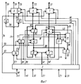
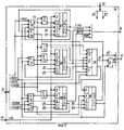
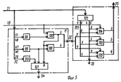
На фиг. 1 изображена структурная схема устройства; на фиг. 2 - структурная схема блока управления устройства; на фиг. 3 - функциональная схема блока состояния устройства; на фиг. 4 - функциональная схема узла реконфигурации устройства; на фиг. 5 - функциональные схемы блока предсказания переносов и блока предсказания четности со связями. In FIG. 1 shows a block diagram of a device; in FIG. 2 is a block diagram of a device control unit; in FIG. 3 is a functional block diagram of a device status block; in FIG. 4 is a functional diagram of a device reconfiguration unit; in FIG. 5 is a functional diagram of a carry prediction unit and a parity prediction unit with links.
Цифрами в прямоугольниках (квадратах) и около них на фиг. 1 - фиг. 5 обозначены: 1 - первый двунаправленный коммутатор; 2 - второй двунаправленный коммутатор; 3 - первый коммутатор; 4 - счетчик; 5 - блок управления; 6 - блок сравнения; 7 - блок памяти информационных разрядов; 8 - блок памяти контрольных разрядов; 9 - второй коммутатор; 10 - регистр; 11 - блок предсказания переносов; 12 - блок предсказания четности байтов; 13 - узел реконфигурации; 14 - блок состояния; 15 - элемент свертки по модулю два; 16 - элемент ИЛИ; 17 - первый выход узла 13, вход сброса счетчика 4 и регистра 10; 18 - второй выход узла 13, счетный вход счетчика 4, управляющий вход блоков 11 и 12; 19 - управляющий выход блока 14, первый управляющий вход узла 13; 20 - второй управляющий вход узла 13, восьмой выход блока 5; 21 - первая группа входов/выходов коммутатора 1; 22 - первая группа входов/выходов коммутатора 2, группа входов/выходов контрольных разрядов устройства; 23 - группа выходов вместе с выходом разряда контроля четности коммутатора 31, группа выходов состояния устройства вместе с выходом разряда контроля четности; 24 - группа выходов состояния блока 14, соответствующие входы элемента 15, группа информационных входов коммутатора 3; 25 - выход запроса устройства, выход элемента 16; 26 - выход конца операции внешнего обмена блока 5 и устройства; 27 - вход задания операций внешнего обмена устройства и блока 5; 28 - входы элемента 16; 29 - вход разряда контроля четности группы информационных входов коммутатора 3, выход элемента 15; 30 - группа выходов коммутатора 9, группа информационных входов регистра 10; 31 - группа разрядных выходов счетчика 4, группа информационных входов блоков 7, 11, первая группа входов блока 12; 32 - группа выходов блока 11, вторая группа входов блока 12; 33 - выход блока 6, выход ошибок устройства; 34 - выход переполнения блока 11, вход фиксации переполнения блока 14, третий управляющий вход узла 13; 35 - вторая группа выходов блока 12, вторая группа информационных входов коммутатора 9; 36 - первая группа выходов блока 12, вторая группа входов блока 6; 37 - управляющий вход блока 14, пятый выход блока 5; 38 - первая группа входов блока 6, группа выходов регистра 10, группа информационных входов блока 8; 39 - управляющий вход коммутатора 9, седьмой выход блока 5; 40 - управляющий вход блоков 7, 8, шестой выход блока 5; 41 - группа адресных входов 7, 8, группа адресных выходов блока 5; 42 - группа выходов блока 8, вторая группа информационных входов/выходов коммутатора 2, первая группа информационных входов коммутатора 9; 43 - вход разрешения счета счетчика 4, первый выход блока 5; 44 - вход управления передачей информации коммутатора 3, четвертый выход блока 5; 45 - вход запрета коммутаторов 1, 2, 3, второй выход блока 5; 46 - вход управления передачей информации коммутаторов 1, 2, 3, третий выход блока 5; 47 - вторая группа тактовых входов устройства; 48 - вторая группа тактовых входов блока 5; 49 - вход запуска устройства и блока 5; 50 - группа входов задания начальных условий устройства и блока 5; 51 - первая группа тактовых входов устройства и блока 5; 52 - группа тактовых входов блока 14, соответствующие тактовые входы группы входов 47; 53 - группа тактовых входов счетчика 4, регистра 10, узла 13; 54 - группа тактовых входов коммутаторов 1, 2, 3; 55 - группа выходов блока 7, группа информационных входов/выходов коммутатора 2; 56 - узел внутреннего управления блока 5; 57 - узел управления внешним обменом блока 5; 58 - узел сравнения блока 5; 59 - узел формирования адресных сигналов блока 5; 60 - первая группа тактовых входов узла 56 (тактовых сигналов > Т3БОВ, > Т4БОВ), соответствующие входы группы входов 51; 61 - группа тактовых входов узла 58 (тактовых сигналов > СИ2-БОВ, > СИ4-БОВ), соответствующие входы группы входов 48; 62 - вторая группа тактовых входов узла 56 (тактовых сигналов > СИ4-БОВ, > СИ6-БОВ), соответствующие входы группы входов 48; 63 - вторая группа тактовых входов узла 57, (тактовых сигналов > С1БОВД, > С2БОВД, > ТИ2-СИ2, > ТИ3-С2), соответствующие входы группы входов 48; 64 - первая группа тактовых входов узла 57 (тактовых сигналов > ТТ2-С1, > ТТ4-С2, > РТИ1П1, > ТТ5-С1, РТИ2В, > Т5БОВ), соответствующие входы группы выходов 51; 65 - группа тактовых входов узла 59 (тактовых сигналов > СИ1-БОВ, > СИ6-БОВ), соответствующие входы группы входов 48; 66 - группа адресных выходов узла 57, первая группа входов узла 58, вторая группа входов которого соединена с группой адресных выходов узла 79 и с группой адресных выходов 41; 67, 68, 69, 80 - триггеры в блоке 14; 70, 75, 76 - элементы И-НЕ в блоке 14; 71, 73, 74, 77, 81 - элементы И-НЕ в блоке 14; 72 - элемент НЕ в блоке 14; 78 - элемент И в блоке 14; 79 - элемент 3И-ИЛИ-НЕ в блоке 14; 82 - вход синхронизации (соответствующий сигналу > СИ3-БОВ) группы входов 52; 83 - вход синхронизации (соответствующий сигналу > СИ4-БОВ) группы входов 52; 84, 85, 86 - инверсные выходы элементов соответственно 70, 75, 76; 87 - инверсный выход элемента 79; 88 - инверсный выход триггера 80; 89 - прямой выход триггера 80, соответствующий разряд выхода 19; 90 - выход элемента 81, соответствующий разряд выхода 19; 91 - элемент И-НЕ в узле 13; 92 - элемент И-НЕ в узле 13; 93, 94 - триггеры в узле 13; 95 - элемент И в узле 13; 96 - элемент И-НЕ в узле 13; 97 - элемент И-НЕ в узле 13; 98, 99 - элементы И в блоке 11; 100, 101 - элементы И в блоке 11; 102- узел формирования сигналов четности в блоке 12; 103 - выход предсказанных сигналов четности байтов узла 102; 104, 105 - коммутатор в блоке 12. Numbers in rectangles (squares) and near them in FIG. 1 - FIG. 5 marked: 1 - the first bi-directional switch; 2 - the second bi-directional switch; 3 - the first switch; 4 - counter; 5 - control unit; 6 - block comparison; 7 - memory block information bits; 8 - memory block control bits; 9 - the second switch; 10 - register; 11 - block prediction hyphenation; 12 - block prediction parity bytes; 13 - reconfiguration node; 14 - state block; 15 - a convolution element modulo two; 16 - element OR; 17 - the first output of the
Идентификаторы сигналов, приведенные над соответствующими связями на фиг. 2-4 соответствуют принятым идентификаторам (обозначениям) этих же сигналов (и связей) в документе [3]. The signal identifiers shown above the corresponding links in FIG. 2-4 correspond to the accepted identifiers (designations) of the same signals (and links) in the document [3].
Цифры около групп входов и выходов на фиг. 5 обозначают номера разрядов или входов и выходов. The numbers around the groups of inputs and outputs in FIG. 5 indicate the numbers of discharges or inputs and outputs.
Двунаправленные коммутаторы 1, 2 и коммутатор 3 предназначены для подключения устройства к общей магистрали центрального процессора и организации обмена информацией с центральным процессором. По структуре и функционированию коммутаторы 1, 2, 3 идентичны одноименным коммутатором прототипа и могут быть построены на микросхемах типа КМ500РС3 или КС1543ИР1. Коммутаторы 1, 2, 3 функционируют следующим образом. При установке на входе 45 логического нуля (> ЕРД=0) обеспечивается запрет записи информации с любой группы входов/выходов коммутаторов во внутренний регистр. При установке на входе 45 логической единицы (> ЕРД=1) обеспечивается запись информации во внутренний регистр коммутаторов 1, 2, 3 с первой или второй группы информационных входов/выходов коммутаторов (в зависимости от управляющих сигналов на входе 46, 44) под действием тактовых импульсов на тактовых входах 54. Группа 54 тактовых входов состоит из двух тактовых входов, на первый из которых подается тактовый сигнал > С1БОВ, фиксирующий входную информацию, а второй - > сигнал С2БОВ, фиксирующий информацию для передачи на выходы.
При формировании сигналов > DЕ1РД=0 и > DЕ3РД=0 на разрядах входов 44, 46 передача информации на входы/выходы с выходов внутреннего регистра блокируется. При формировании сигналов > DЕ1РД=1, > DЕ3РД=1 обеспечивается передача информации со второй группы информационных входов/выходов и со входов 24 и 29 на информационные входы внутренних регистров для записи в регистры и передача информации с выходов внутренних регистров коммутаторов на выходы 23 коммутатора 3 и (при формировании сигнала > SРД=0 на соответствующем разряде выхода 46 (см. фиг. 2)) на первую группу информационных входов/выходов коммутаторов 1, 2. При формировании сигнала > SРД=1 (при сигнале > DЕ1РД=1) обеспечивается передача информации в обратном направлении. Передача информации в обратном направлении в коммутаторе 3 не предусмотрена. When generating signals> DE1RD = 0 and> DE3RD = 0 at the bits of the
Счетчик 4 предназначен для промежуточного запоминания значений часов, компаратора, таймера процессора и для модификации (счета) указанных значений. Счетчик 4 может быть реализован, например, на микросхемах типа КМ500СТ2 или КС1543ИЕ1. Счетчик 4 функционирует следующим образом. При логическом нуле (> Е2С4=0) на входе 43 счетчик 4 устанавливается в режим записи кода с информационной группы входов под действием тактовых сигналов на входах 53. При логической единице (> Е2С4=1) на входе 43 счетчик 4 устанавливается в режим счета при логической единице на входе 18 или в режим хранения при логическом нуле на входе 18.
Описанные режимы устанавливаются при логической единице на входе 17. При логическом нуле на входе 17 счетчик 4 "сбрасывается" под действием тактовых сигналов на входах 53. The described modes are set with a logical unit at
Блок 5 управления (фиг. 2) предназначен для формирования управляющих сигналов для всех узлов и блоков устройства, для формирования адресов часов, коммутатора и таймера процессора в требуемый временной промежуток времени и для формирования сигнала конца операции внешнего обмена на выходе 26. The control unit 5 (Fig. 2) is designed to generate control signals for all nodes and units of the device, to generate the addresses of the clock, switch and processor timer in the required time period and to generate the signal for the end of the external exchange operation at the
Структурная схема блока 5 изображена на фиг. 2. Блок 5 содержит узел 56 внутреннего управления, узел 57 управления внешним обменом, узел 58 сравнения, узел 59 формирования адресных сигналов. The block diagram of
Структурная схема блока 5 отличается от структурной схемы блока управления прототипа наличием дополнительного выхода 20, на разрядах которого формируются сигналы > РКМ1, > 3ПБОВ, > СПАДР2, РТП, > Р4С2, формирование которых уже предусмотрено в блоке управления прототипа. The block diagram of
В связи с тем, что изменения структуры блока 5 однозначно определяются наличием признака - выхода 20 и алгоритмом функционирования узла 13, авторы и заявитель считают нецелесообразным включать признаки блока управления в формулу изобретения. Due to the fact that the structural changes of
Моменты появления и назначения сигналов 3ПБОВ, СПАДР2, > Р4С2, > РКМ2, > РТП2, > СБРОС, РТП, > РКМ1, > УПР, УПР, > WRRАМД, > Е1РАМД, > АДР1, > АДР2, > ТСП, > СПАДР1 будет пояснено ниже и при описании функционирования устройства. The moments of appearance and destination of signals 3PBOV, SPADR2,> P4C2,> RKM2,> RTP2,> RESET, RTP,> RKM1,> UPR, UPR,> WRRAMD,> E1RAMD,> ADR1,> ADR2,> TSP,> SPADR1 will be explained below and when describing the operation of the device.
Блок 6 сравнения предназначен для сравнения значений контрольных разрядов с группы выходов 38 регистра 10 и с группы выходов 36 для формирования сигналов ошибок на выходе 33.
Блок 7 памяти информационных разрядов и блок 8 памяти контрольных разрядов предназначены для хранения кодов текущих значений часов (компаратора, таймера процессора) и контрольных кодов значений побайтных сигналов четности кодов текущих значений часов (компаратора, таймера процессора). Блоки 7, 8 функционируют следующим образом. При формировании сигнала > Е1РАМД=0 на соответствующем разряде входа 40 выходы блоков 7, 8 блокируются, а при формировании сигнала > Е1РАМД= 1 и сигнала > WRRАМД=0 на соответствующих разрядах входа 40 на выходы блоков 7, 8 считывается информация, хранимая в блоках по адресу, код которого установлен на входах 41. При формировании сигналов > Е1РАМД=1 и > WRRАМД=1 осуществляется операция записи в блоках 7, 8 по адресу, код которого установлен на входах 41.
Коммутатор 9 предназначен для передачи контрольных кодов сигналов четности с группы выходов блока 8 (при сигналах > УПР=1, УПР=0 на соответствующих разрядах входа 39) или с группы выходов 35 (при сигналах > УПР=0, УПР=1). The
Регистр 10 предназначен для временного хранения контрольных кодов сигналов четности, передаваемых с выходов блока 8 или выходов 35 блока 12.
Блок 11 предсказания переносов (фиг. 5) предназначен для формирования сигналов побайтных предсказанных переносов на выходах 32, предсказанного сигнала переполнения на выходе 34.
Блок 11 может быть построен на элементах И 98, 99, 100, 101. При логическом нуле на входе 18 блока 11 на всех выходах 32, 34 устанавливается логический нуль (т.е. формирование переносов блокируется). При логической единице на входе 18 блока 11 обеспечивается формирование сигналов переносов в соответствии с алгоритмом, задаваемом функциональной схемой блока 11 на фиг. 5.
Структура и функционирование блока 11 идентичны структуре и функционированию одноименного блока прототипа с тем отличием, что количество выходов в группе выходов 32 равно двум (вместо шести) и введен управляющий вход 18. The structure and functioning of
Блок 12 предсказания четности байтов (фиг. 5) предназначен для формирования побайтных сигналов четности (на выходах 36) для кода, установленного на входе 31 и предсказанных побайтных сигналов четности (на выходах 35) для кода, установленного на входе 31 после его модификации. Блок 12 содержит узел 102 формирования сигналов четностей, коммутаторы 104, 105. На выходе 36 формируются побайтные сигналы четностей для кода, установленного на входе 31. На выходах 103 формируются предсказанные сигналы четности для каждого байта кода, установленного на входе 31, т.е. предполагается, что к значению кода каждого байта (в младший разряд байта) прибавлена единица и для полученного кода - суммы формируется предсказанный сигнал четности на соответствующем выходе 103. Узел 102 может быть построен на элементах ПЗУ соответствующим образом закодированных (как в прототипе). В зависимости от наличия или отсутствия переноса в байт кода на соответствующий выход 35 передается сигнал либо с соответствующего выхода 103, либо с соответствующего выхода 36. При логическом нуле на входе 18 на соответствующий выход группы выходов 35 всегда передается сигнал с соответствующего выхода группы выходов 36. При логической единице на входе 18 на соответствующий выход группы выходов 35 всегда передается сигнал с соответствующего выхода группы выходов 103. The byte parity prediction block 12 (Fig. 5) is used to generate byte parity signals (at the outputs 36) for the code installed at
Структура блока 12 отличается от структуры одноименного блока прототипа наличием дополнительного коммутатора 104 со связями. The structure of
Так как изменения в структуре блоков 11, 12 обусловлены наличием признака - связи 18, то авторы считают нецелесообразным описывать структуру блоков 11 и 12 в формуле изобретения. Since changes in the structure of
Узел реконфигурации 13 предназначен для формирования управляющих сигналов, обеспечивающих автоматическое изменение режима функционирования устройства (реконфигурацию связей в устройстве) так, что устройство из режима "счета" (часов, компаратора, таймера процессора) переходит в режим "сохранения счета часов". Узел 13 (фиг. 4) может быть построен на элементах И-НЕ 91, 92, 96, 97, И 95, триггерах 93, 94. В исходном состоянии на разрядах 89, 90 входа 19 установлены логические нули, под действием которых триггеры 93, 94 удерживаются в "нулевом" состоянии, а на выходах 17, 18 - логические единицы. При установке на разряде 90 входа 19 логической единицы триггер 94 переходит в "единичное" состояние только при появлении сигналов > Р4С2=1, РТП=1, > РО=1 на соответствующих разрядах входа 20. При этом, при последующем появлении сигнала РТП=0 триггер 94 вновь переходит в "нулевое" состояние и сохраняет его до повторного появления сигнала > Р4С2=1, > РО=1. В момент появления сигнала > Р4С2=1 на инверсном выходе элемента 96 устанавливается логический ноль, который удерживает логическую единицу на выходе 18 независимо от состояния разряда 89 входа 19. Логический нуль на выходе 18 устанавливается только при логической единице на разряде 89 входа 19, наличии сигнала > Р4С2=0 и "нулевом" состоянии триггера 94. Всякий раз при появлении сигналов > 3ПБОВ=1, > СПАДР2=1 триггеры 93, 94 устанавливаются в "нулевое" состояние. При этом при логической единице на разряде 89 и сигнале > РКМ1=1 на выходе 17 устанавливается логический нуль, а триггер 93 устанавливается в "единичное" состояние. Триггеры 93, 94 переключаются под действием синхросигналов > СИ3=1, > СИ4=1, формируемых последовательно на входах 82, 83 группы входов 53.
На фиг. 4 буквами D, R, Е около входов триггеров 93, 94 (так же как и на фиг. 3 около входов триггеров 67, 68, 69, 80) обозначены соответственно информационный вход, вход сброса (при логическом нуле), вход запрета переключения (при логическом нуле). Буквами ![]()
![]()
Блок 14 состояния (фиг. 3) предназначен для формирования сигналов состояния устройства, в том числе сигнал ( > ПРТП) прерывания от таймера процессора, сигнал ( > ПРКМ) прерывания от компаратора, сигнал ( > ПЧС) прерывания от часов, сигнал (> ПРКФ) прерывания на реконфигурацию. The state block 14 (Fig. 3) is intended for generating device status signals, including an interrupt signal (> PRTP) from the processor timer, an interrupt signal (> PRKM) from the comparator, an interrupt signal (> ППС) from a clock, a signal (> PRKF ) interruptions for reconfiguration.
Блок 14 может быть построен на элементах И-НЕ 70, 71, 75, 73, 76, 77, 74, 81, НЕ 72, 3И-ИЛИ 79, триггерах 67, 68, 69, 80. Триггеры 67, 68, 69, 80 функционируют так же как и триггеры в узле 4 (см. описание узла 4) и могут быть реализованы на микросхемах КС1543ТМ2 или КМ500ТТ2.
Триггеры 67, 68, 69 устанавливаются в "нулевое" состояние при формировании сигнала > СБРОС=1 на соответствующем разряде входа 37. При этом триггеры 67, 68, 69 устанавливаются в "нулевое" состояние только в том случае, если они находились в "единичном" состоянии или находится в "единичном" состоянии триггер 80. Если же триггер 67 (68, 69) находится в "нулевом" состоянии (при нулевом состоянии триггера 80) и имеет место одновременное формирование сигналов СБРОС=1, > РЧС2=1 (> РКМ2=1, > РТП2=1), > РО=1, на разрядах входа 37, то установка "нулевого" состояния триггера 67 (68, 69) предотвращается (в связи с блокировкой элемента 71 (73, 74) и обеспечивается установка "единичного" состояния указанного триггера путем записи логической единицы со входа > РО=1. Таким образом, в отличие от прототипа предотвращается потеря сигналов прерывания (благодаря использованию элементов 70, 71 (73, 75 и 74, 76) при формировании сигнала > СБРОС=1). Описанный положительный эффект является дополнительным по отношению к основному и зависимым от основного. Если логическая единица со входа 34 ( > РО=1) будет зафиксирована в одном из триггеров 67, 68, 69 при одновременном появлении сигнала > РЧС2= 1 (> РКМ2=1, > РТП2=1) и после этого не появляется сигнал > СБРОС=1 вплоть до повторного появления сигнала > РО=1, то при повторном появлении сигнала > РО= 1 при одновременном появлении сигнала > РЧС2=1 ( > РКМ2= 1, > РТП2= 1) обеспечивается переключение в "единичное" состояние (через элемент 79) триггера 80. На разрядах 89, 90 устанавливаются при этом логические единицы. При этом на разряде 90 логическая единица устанавливается до появления синхросигналов > СИ3=1, > СИ4=1, а на разряде 89 выхода 89 устанавливается логическая единица после сигнала > СИ3=1 в момент действия сигнала > СИ4= 1. В результате обеспечивается своевременное переключение триггеров в узле 13 и изменение режимов функционирования счетчика 4. При появлении сигналов > 3ПБОВ= 1, > СПАДР2=1 триггер 80 устанавливается в "нулевое" состояние.
Устройство функционирует следующим образом. В исходном состоянии на входы 47, 51 не поступают тактовые сигналы. После включения электропитания по последовательным цепям сброса, не показанным на чертежах, во все триггерные и регистровые элементы памяти заносятся нулевые коды. На входах 27 устанавливается нулевой код. На входах 50 устанавливаются требуемые коды начальных условий. На вход 49 подается запускающий сигнал, представляющий импульсы длительностью 500 нс, поступающие на вход 49 с периодичностью 1 мкс. Затем осуществляется запуск тактовых сигналов на входах 47, 52. На вход 47 начинают поступать тактовые сигналы задающей серии: > С1БОВ (> С1БОВД), > С2БОВ (> С2БОВД), основной; серии: > СИ1-БОВ, > СИ2-БОВ, > СИ3-БОВ, > СИ4-БОВ, > СИ6-БОВ; процессорной серии: > ТИ2-С2, > ТИ3-С2. На вход 51 начинают поступать тактовые сигналы вспомогательной основной серии: > Т3БОВ, > Т4БОВ, > Т5БОВ и вспомогательной процессорной серии: > ТТ2-С1, > ТТ4-С2, > ТТ5-С1, > РТИ1П, РТИ2В. Сигналы > С1БОВ (> С1БОВД) и > С2БОВ (> С2БОВД) представляют собой импульсы длительностью меньшей 20 нс и большей 10 нс, поступающие каждый на "свой" тактовый вход с периодичностью (40-46,6) нс. При этом, при отсутствии импульса > С1БОВ (> С1БОВД) появляется импульс > С2БОВ (> С2БОВД) и наоборот. Сигналы > СИ1-БОВ, > СИ2-БОВ, > СИ3-БОВ, > СИ4-БОВ, > СИ5-БОВ, > СИ6-БОВ представляют собой сигналы, длительностью такой же как и сигналы > С1БОВ (> С2БОВ), поступающие последовательно каждый на "свой", соответственно, первый, второй, третий, четвертый, пятый, шестой тактовые входы. Периодичность поступления каждого импульса на "своем" тактовом входе равна (120-140) нс. При этом импульс > СИ-БОВ появляется на i-ом тактовом входе через (20-23,6) нс после начала появления импульса > СИ(i-1)-БОВ на (i-1)-ом тактовом входе. Сигналы > ТИ2-С2 и > ТИ3-С2 соответствуют сигналам > СИ2-БОВ и > СИ3-БОВ, но появление импульсов > ТИ2-С2 и > ТИ3-С2 не синхронизировано с появлением импульсов > СИ2-БОВ и > СИ3-БОВ. По этой причине моменты появления импульсов > ТИ2-С2 могут совпадать с моментами появления импульсов > CИ2-БОВ или > СИ4-БОВ, > СИ6-БОВ, а моменты появления импульсов > ТИ3-С2 могут совпадать с моментами появления импульсов > СИ1-БОВ, > СИ5-БОВ. Сигнал > СИ5-БОВ в устройство не используется. Сигналы > Т3БОВ, > Т4БОВ, > Т5БОВ представляют собой импульсы длительностью (40-46,6) нс, поступающие каждый на "свой" тактовый вход с периодичностью (120-140) нс. При этом импульс > Т3БОВ действует во время действия импульсов > СИ2-БОВ, > СИ3-БОВ, импульс > Т4БОВ действует во время действия импульсов > СИ3-БОВ, > СИ4-БОВ, импульс > Т5БОВ действует во время действия импульсов > СИ4-БОВ, > СИ5-БОВ. Тактовые сигналы > Т1БОВ, > Т2БОВ, > Т6БОВ в устройстве не используются. The device operates as follows. In the initial state,
Сигналы > ТТ2-С2, > ТТ4-С2, > ТТ5-С1 аналогичны сигналам > Т2БОВ, > Т4БОВ, > Т5БОВ, но формируются асинхронно, т.е. сигналы > ТТ2-С2 (> ТТ4-С2) могут совпадать по времени появления с сигналами > Т2БОВ, > Т4БОВ, > Т6БОВ, а сигнал > ТТ5-С1 может совпадать с сигналами > Т1БОВ, > Т3БОВ, > Т5БОВ. Signals> TT2-C2,> TT4-C2,> TT5-C1 are similar to signals> T2BOV,> T4BOV,> T5BOV, but they are formed asynchronously, i.e. signals> TT2-C2 (> TT4-C2) can coincide in time of appearance with signals> T2BOV,> T4BOV,> T6BOV, and the signal> TT5-C1 can coincide with signals> T1BOV,> T3BOV,> T5BOV.
Сигналы > РТИ1П1 и РТИ2В представляют собой импульсы, длительность которых кратна (120-140) нс, а периодичность появления асинхронна, т.е. моменты появления заранее не определены, т.к. соответствуют моментам включения (выключения) синхронизации центрального процессора при приостановках его работы в связи с взаимодействием оперативной памяти с каналами ввода-вывода. Signals> RTI1P1 and RTI2B are pulses whose duration is a multiple of (120-140) ns, and the frequency of occurrence is asynchronous, i.e. the moments of occurrence are not predetermined, because correspond to the moments of turning on (turning off) the synchronization of the central processor during interruptions in its operation in connection with the interaction of RAM with input / output channels.
Сигналы > ТТ2-С2, > ТТ4-С2, > ТТ5-С1, > РТИ1П1, > РТИ2В, > ТИ2-С2, > ТИ3-С2 необходимо использовать для частичной синхронизации работы устройства с работой центрального процессора при обмене информацией, что связано с конкретной реализацией устройства, его применением. Signals> TT2-C2,> TT4-C2,> TT5-C1,> RTI1P1,> RTI2V,> TI2-C2,> TI3-C2 must be used to partially synchronize the operation of the device with the operation of the central processor during information exchange, which is associated with a specific the implementation of the device, its use.
Затем микропрограммно (с помощью центрального процессора) через входы/выходы 22, 21 устанавливаются нулевые показания (нулевой код) часов, компаратора, таймера процессора путем установки на входах 27 последовательно, каждый раз после появления сигнала готовности на выходе 26, кода записи показаний часов, компаратора, таймера процессора. Then, the firmware (using the central processor) through the inputs / outputs 22, 21 sets the zero readings (zero code) of the clock, the comparator, the processor timer by setting the
Затем на входах 27 устанавливается код чтения часов и, после появления сигнала готовности на выходе 26, устройство считается приведенным в исходное состояние. Then, the clock reading code is set at the
Таким образом, на входе 27 могут устанавливаться следующие коды:
- нулевой код - при отсутствии операций внешнего обмена информацией (с центральным процессором или процессором);
- код записи часов (КЗЧ) - для записи нового значения часов;
- код записи компаратора (КЗК) - для записи нового значения компаратора;
- код записи таймера процессора (КЗТ) - для записи нового значения таймера процессора;
- код чтения часов (КЧЧ) - для чтения значения часов;
- код чтения компаратора (КЧК) - для чтения значения компаратора;
- код чтения таймера процессора (КЧТ) - для чтения значения компаратора.Thus, the following codes can be set at input 27:
- zero code - in the absence of external information exchange operations (with a central processor or processor);
- code for recording hours (КЗЧ) - to record a new value for hours;
- Comparator Record Code (CLC) - to record a new comparator value;
- processor timer recording code (CTC) - to record a new processor timer value;
- code for reading the clock (KCHCH) - to read the value of the clock;
- comparator read code (CCC) - to read the value of the comparator;
- processor timer read code (CCT) - to read the value of the comparator.
При этом при установке на входе 27 кодов КЗЧ, КЗК, КЗТ на входах/выходах 21 устанавливаются коды значений часов, компаратора таймера процессора, передаваемых из центрального процессора, а на входах/выходах 22 - их контрольные коды четности. В блоке 5, после появления сигнала > ТСП на входе узла 58 и появления последовательно сигналов > АДР1 и > АДР2 на соответствующих выходах узла 59, на соответствующих выходах узла 56 появляются в соответствующей последовательности сигналы > СПАДР1 и > СПАДР2. Под действием сигнала > Е1РАМД на разряде входа 40 и кода на входе 27 узла 57 и совокупности тактовых сигналов на входах 63, 64 узла 57 на выходах 44, 45, 46 узла 57 и блока 5 формируются сигналы в требуемой последовательности, обеспечивающие запись кодов, установленных на входах/выходах 21, 22 во внутренний регистр коммутаторов 1, 2. Однако только после появления требуемой комбинации сигналов УПР, > УПР, > Е2С4, > WRRАМД, > Е1РАМД на выходах 39, 43, 40, обеспечивающих перезапись кодов из внутренних регистров коммутаторов 1, 2 в счетчик 4 и регистр 10 и далее в блоки памяти 7,8, под действием сигнала > СПАДР2 на входе узла 57 на выходе 26 появляется сигнал (логическая единица) конца операции внешнего обмена. Параллельно осуществляется контроль по четности принятых кодов с помощью блоков 11, 12, 6. Если имеет место ошибка, то на выходе 33 формируется код ошибки. Сигналы (логические единицы) > АДР1, > АДР2 появляются последовательно друг за другом на время (120-130) нс каждый (в промежуток времени (> СИ1-БОВ - > СИ6-БОВ) с периодичностью (240-260) нс. Сигналы > СПАДР1, > СПАДР2 идентичны сигналам соответственно > АДР1, > АДР2, но появляются только при появлении сигнала > ТСП на выходе узла 58. At the same time, when the input of 27 codes КЗЧ, КЗК, КЗТ is set at the inputs / outputs 21, codes for the values of the clock, the comparator of the processor timer are transmitted from the central processor, and at the inputs /
Описанный режим функционирования устройства является режимом записи (РЗ). The described mode of operation of the device is a recording mode (RE).
При установке на входе 27 кодов КЧЧ, КЧК, КЧТ устройство начинает функционировать в режиме чтения, который отличается от режима счета (РС), устанавливаемом при нулевом коде на входе 53, только тем, что во время действия сигнала > СПАДР1 на выходах 44, 45, 46 блока 5 формируется такая совокупность сигналов, которая обеспечивает запись кодов, считанных из блоков 7, 8 и со входов 29, 24 во внутренний регистр коммутаторов 1, 2, 3 и выдачу их на входы/выходы 21, 22, 23 в требуемый момент времени, определяемый моментом появления импульса ТИ2-С2. При этом как и в режиме чтения сигнал (логическая единица) на выходе 26 появляется под действием сигнала > СПАДР2 в момент действия сигнала > ТТ4-С2. Установка логического нуля на выходе 26 как при режиме записи, так и при режиме чтения осуществляется через (120-130) нс в моменты действия сигналов > ТТ4-С2, РТИ2В. В режиме чтения осуществляется также формирование сигнала (логической единицы) сброса (> СБРОС) на разряде выхода 37 блока 5 (см. фиг. 2), под действием которого осуществляется сброс (обнуление) всех триггеров состояния в блоке 14 (фиг. 3), выходы которых соединены с выходами 24, кроме триггера 80 состояния реконфигурации. Коды указанных триггеров, представляющие собой биты динамического кода состояния средств отсчета времени (ДКС СОВ), записываются во внутренний регистр коммутатора 3 для передачи в центральный процессор для хранения и анализа. When 27 codes of KCHCh, KChK, KChT are installed at the input, the device starts functioning in the reading mode, which differs from the counting mode (PC), set when the code at
В контрольный разряд внутреннего регистра коммутатора 3 записывается код значения четности для кода на входе 24 для контроля достоверности передачи кода ДКССОВ с группы выходов 23 коммутатора 3 в центральный процессор. Триггер 80 в блоке 14 сбрасывается только в момент появления сигналов > 3ПБОВ= 1 и > СПАДР=2, т.е. когда в устройстве заканчивается режим записи. Сигнал > ТСЦ на выходе узла 58 формируется под действием сигналов > СИ2-БОВ, > СИ4-БОВ при равенстве кодов адреса на входе 41 и на выходе 66. На выходе 66 формируется код адреса часов или компаратора или таймера процессора в зависимости от кода операции, установленного на входе 27 соответственно КЗЧ, КЧЧ или КЗК, КЧК или КЗТ, КЧТ. В режиме счета (когда на входе 27 установлен нулевой код) на выходах 66 (фиг. 2) также устанавливается нулевой код. В результате на выходе узла 58 устанавливается нулевой код. На выходах 44, 45, 46 устанавливается такая комбинация сигналов, при которой коммутаторы 1, 2, 3 отключаются от входов/выходов. In the control bit of the internal register of
С каждым появлением сигнала (логической единицы) >ГИ на входе 49 начинает формироваться последовательность сигналов АДР1 и >АДР2, а на выходе 41 формируется последовательно код адресов часов (>РЧС), код адреса компаратора (>РКМ), код адреса таймера процессора ( >РТП). Каждый новый код на выходе 41 удерживается в течение действия сигналов >АДР1 и >АДР2. Появление сигнала >РКМ2 (>РЧС2, >РТП2) на соответствующем разряде выхода 37 совпадает по времени с появлением сигнала >АДР2 и установкой на выходе 41 кода адреса компаратора (часов, таймера процессора). With each occurrence of a signal (logical unit)> GI at
Сигналы >РКМ2, >РТП2, >РЧС2 управляют фиксацией сигнала переполнения (переноса) со входа 34Т блока 14 отдельно для компаратора, таймера процессора, часов. Дополнительно, идентификация режимов записи, чтения и счета устройства в блоке 14 осуществляется с помощью сигналов >СПАДР2, >3ПБОВ в разрядах входа 37. Signals> RKM2,> RTP2,> RFCh2 control the fixation of the overflow (transfer) signal from the input 34T of
В режиме счета (РС) (так же как и чтения) в течение действия сигнала >АДР1 осуществляется чтение кодов из блоков 7, 8 и запись их в счетчик 4 и регистр 10 под действием сигналов >СИ3-БОВ, >СИ4-БОВ благодаря установке соответствующей комбинации управляющих сигналов на входах 39, 40, 43. На выходах 36 формируется контрольный код, который сравнивается с контрольным кодом с выходов регистра 10. Сигнал ошибки (если она возникла) формируется на выходе 33. В течение действия сигнала >АДР2 осуществляется модификация (счет) кодов, запомненных в счетчике 4 и запись в регистр 10 предсказанного контрольного кода со входов 35 под действием сигналов >СИ3-БОВ, >СИ4-БОВ благодаря установке на входах 39, 43 соответствующей комбинации сигналов. С помощью блоков 6, 12 осуществляется контроль правильности модификации кода с формированием на выходе 33 соответствующего сигнала. Возможные сигналы переполнения (логическая единица переноса со старшего разряда модифицируемого в счетчике 4 кода) с выхода 34 фиксируется в блоке 14 под действием сигналов >СИ3-БОВ, >СИ4-БОВ (триггерах 67, 68, 69 (фиг. 3) при модификации кодов соответственно часов, компаратора, таймера процессора). На соответствующих выходах 24 и выходе 25 формируется сигнал - логическая единица. In counting mode (PC) (as well as reading) during the action of the signal> ADR1, codes from
Если сигнал переноса >РО (второй сигнал переноса) при модификации кода часов, компаратора, таймера процессора появляется в тот момент, когда еще не сброшен предыдущий сигнал переноса (первый сигнал переноса), возникший при модификации кода соответственно часов, компаратора, таймера процессора и зафиксированный в триггере соответственно 67, 68, 69, то через элементы 78, 79 (фиг. 3) устанавливается в единичное состояние триггер 80 под действием сигналов >СИ3-БОВ, >СИ4-БОВ. На разрядах 90 и 89 выхода 19 и выхода 24 устанавливаются логические единицы. Устройство переходит в режим реконфигурации (РРК). В момент действия ближайшего (по времени) сигнала >РКМ1= 1 формируется логический нуль на выходе 17 (фиг. 4), под действием которого вместо кода компаратора в счетчике 4 устанавливается нулевой код. Параллельно устанавливается в единичное значение триггер 93 (фиг. 4), благодаря чему в дальнейшем в режиме реконфигурации предотвращается формирование логического нуля на выходе 17. Кроме того, что второй сигнал переноса, возникший при модификации кода часов (от часов) фиксируется в триггере 80 блока 14 он, а также и все последующие сигналы переноса от часов в режиме реконфигурации фиксируются в триггере 94 узла 13 (фиг. 4). В результате в момент модификации кода, который в других режимах представлял код компаратора, будет осуществляться подсчет количества переносов от часов, так как на выходе 18 устанавливается единица на время действия сигналов >РКМ1=1 и >РКМ2=1. If the transfer signal> PO (second transfer signal) when modifying the code of the clock, comparator, processor timer appears at the moment when the previous transfer signal (first transfer signal) that occurred when the code of the clock, comparator, processor timer and in the trigger, respectively, 67, 68, 69, then through the
В момент появления сигнала РТП=0 (на разряде входа 20) триггер 94 узла 13 сбрасывается (обнуляется) и в момент действия последующего сигнала >РЧС2= 1 вновь в триггере 94 может зафиксироваться последующий сигнал переноса от часов, который прибавляется к уже подсчитанному количеству сигналов переносов, код которого модифицируется в счетчике 4 в момент действия сигнала >РКМ2=1. Так как триггер 94 сбрасывается уже в момент действия сигнала >РТП1=1, то к моменту действия сигнала >РТП2=1 на всех входах элемента 91 узла 13 устанавливаются логические единицы и, следовательно, на выходе 18 узла 13 устанавливается логический нуль. В результате код таймера, записанный в счетчике 4, модифицироваться не будет и без изменений вновь будет записан в блок памяти 7, а его контрольные разряды без изменений будут записаны в блок памяти 8. Это связано с тем, что при установке на выходе 18 логического нуля счетчик 4 переходит в режим хранения, а в блоке 12 контрольный код с выходов 36 передается на выходы 35 (см. фиг. 5). При этом в блоке 11 блокируется формирование сигнала переноса (см. фиг. 5). Только при задании в устройстве операции внешнего обмена-записи нового значения часов, компаратора или таймера процессора в момент одновременного действия сигналов >3ПБОВ= 1 и >СПАДР2= 1 в блоке 14 и узле 13 осуществляется сброс триггеров 80, 93, 94 и устройство переходит в режим счета. При этом на разрядах 89, 90 выхода 19 и выхода 24 устанавливаются логические нули. На выходах 17, 18 узла 13 постоянно устанавливаются логические единицы. At the moment the signal RTP = 0 appears (at the input bit 20), the
Во всех случаях по сигналу на выходе 25 центральный процессор "задает" в устройстве режим чтения по адресу часов путем установки на входе 27 кода КЧЧ. Параллельно осуществляется чтение кода состояния ДКССОВ устройства через входы 24 и выходы 23. In all cases, according to the signal at
Покажем, что с помощью предложенного устройства благодаря использованию узла реконфигурации со связями обеспечивается решение в процессоре ЭВМ всех задач, решаемых прототипом. We show that using the proposed device through the use of the reconfiguration node with connections, a solution is provided in the computer processor for all the tasks solved by the prototype.
Предлагаемое устройство предназначено для реализации средств отсчета времени (СОВ) в центральном процессоре (ЦП) следующим способом. The proposed device is intended for the implementation of timers (SOW) in the Central processor (CPU) in the following way.
В соответствии с принципами функционирования современных ЭВМ, например, известной ЕС ЭВМ, с помощью прототипа в процессоре обеспечивается организация (не считая интервального таймера) следующих средств отсчета времени: часов (ЧС), компаратора (КМ), таймера процессора (ТП), значение каждого из которых представляется 52-х разрядным двоичным кодом. В процессе работы (функционирования) средств отсчета времени в младший (51-й разряд кода часов каждую микросекунду прибавляется единица (таким образом осуществляется счет (модификация часов)), значение компаратора каждую микросекунду сравнивается с промодифицированным значением часов, а из младшего (51-го разряда кода таймера процессора каждую микросекунду вычитается единица. При этом в момент, когда значение компаратора становится меньше значения часов или знак (нулевой) разряд таймера процессора изменяется на противоположный (становится равным логической единице), в процессор формируется запрос на внешнее прерывание от компаратора или от таймера процессора. Средства отсчета времени рассматриваются как внешние устройства по отношению к процессору. In accordance with the principles of functioning of modern computers, for example, the well-known EU computer, using the prototype in the processor, the following time counters are organized (not counting the interval timer): hours (ES), comparator (CM), processor timer (TP), the value of each of which appears to be 52-bit binary. In the process of operation (functioning) of time counters, the unit is added to the lowest (51st digit of the clock code every microsecond (thus, counting (modification of the clock) is performed)), the value of the comparator is compared to the modified clock value every microsecond, and from the younger (51st a unit of the processor timer code is subtracted every microsecond, and at the moment when the value of the comparator becomes less than the clock or the sign (zero) of the processor timer is reversed (becomes I am equal to a logical one), the processor is formed on the external interrupt request from the comparator or of the processor clock. Means timing are treated as external devices to the processor.
При этом на работу часов не должны влиять такие состояния, режимы функционирования процессора и процедуры, выполняемые в процессоре, как: "ожидание"/"счет", "задача"/"супервизор", "стоп"/"работа", "покомандная работа", "потактная работа", режим "контроля", "сброс" процессора, "начальный сброс", "программный сброс", "начальный программный сброс", "сброс с очисткой", "начальная загрузка". At the same time, the operation of the clock should not be influenced by such states, processor operating modes, and procedures performed in the processor as: “wait” / “count”, “task” / “supervisor”, “stop” / “work”, “command operation "," push operation "," control "mode," reset "of the processor," initial reset "," software reset "," initial software reset "," reset with cleaning "," initial load ".
Значение часов должно становиться нулевым после "сброса при включении питания". The clock should be set to zero after a “power-on reset”.
Значение компаратора должно сохраняться при таких состояниях, режимах функционирования процессора и процедурах, выполняемых в процессоре, как: "ожидание"/"счет", "задача"/"супервизор", "стоп"/"работа", "покомандная работа", "контактная работа", "режим контроля", "сброс" процессора, "программный сброс", "начальная загрузка". The value of the comparator should be maintained under such conditions, processor operating modes and procedures performed in the processor as: “wait” / “count”, “task” / “supervisor”, “stop” / “work”, “command operation”, “ contact work "," control mode "," reset "of the processor," software reset "," boot ".
Значение компаратора должно становиться нулевым и должен формироваться в процессор запрос на внешнее прерывание от компаратора после "начального сброса" процессора, "начального программного сброса", "сброса с очисткой", "сброса при включении питания". The value of the comparator should become zero and a request for an external interrupt from the comparator should be formed in the processor after the "initial reset" of the processor, the "initial software reset", "reset with cleaning", "reset at power-up".
Значение таймера процессора должно сохраняться и таймер процессора должен уменьшаться при таких состояниях, режимах функционирования процессора и процедурах, выполняемых в процессоре, как: "ожидание"/"счет", "задача"/"супервизор", "работа" (в том числе и при выполнении команды в процессе покомандной работы), "сброс процессора", "программный сброс", "начальная загрузка". The processor timer value should be saved and the processor timer should decrease under such conditions, processor operating modes and procedures performed in the processor as: “wait” / “count”, “task” / “supervisor”, “work” (including when executing a command in the process of team work), "processor reset", "software reset", "boot".
Значение таймера процессора должно сохраняться и таймер процессора не должен уменьшаться при состоянии "стоп" процессора. Значение таймера процессора должно становиться нулевым при "начальном сбросе" процессора, "начальном программном сбросе", "сбросе с очисткой", "сбросе при включении питания". The processor timer value must be maintained and the processor timer must not decrease when the processor stops. The processor timer value should become zero during the "initial reset" of the processor, "initial software reset", "reset with cleaning", "reset at power-up".
После выполнения таких процедур в процессоре, как "сброс" процессора, "программный сброс", "начальный сброс", "начальный программный сброс", "сброс с очисткой" процессор переходит в состояние "стоп", из которого он выводится оператором или сигналом от другого процессора. After performing such procedures in the processor as “resetting” the processor, “soft reset”, “initial reset”, “initial soft reset”, “reset with cleaning”, the processor switches to the “stop” state from which it is output by the operator or by a signal from another processor.
В состоянии "стоп" или в режиме "начальной загрузки" процессор может находиться неопределенный интервал времени, больший 1 с. При этом часы должны непрерывно производить отсчет времени без потери точности, а значение компаратора должно сравниваться со значением часов с формированием соответствующих запросов в процессор на внешнее прерывание. Таймер процессора должен осуществлять отсчет интервала времени в течение выполнения процедур "сброс" процессора, "программный сброс", "начальная загрузка" до установки состояния "стоп" процессора, при котором таймер процессора должен остановиться. При выполнении таких процедур, как "начальный сброс", "начальный программный сброс", "сброс с очисткой", "сброс при включении питания" значение таймера процессора и компаратора устанавливается равным нулевому и таковым сохраняется после установки состояния "стоп" процессора. При выполнении процедуры "сброс при включении" значение часов устанавливается равным нулевому, однако сразу после сброса часы должны начать отсчет времени. Во всех случаях счет в часах и таймере процессора должен осуществляться с одинаковой скоростью. In the "stop" or in the "boot" mode, the processor may be an indefinite time interval greater than 1 s. In this case, the clock should continuously count down the time without loss of accuracy, and the comparator value should be compared with the clock value with the formation of the corresponding requests to the processor for an external interrupt. The processor timer should count down the time interval during the execution of the processor “reset”, “soft reset”, “boot” procedures until the processor stops, at which the processor timer should stop. When performing procedures such as “initial reset”, “initial software reset”, “reset with cleaning”, “reset at power-up”, the timer value of the processor and comparator is set to zero and remains the same after setting the processor's “stop” state. When performing the “reset on power-up” procedure, the clock value is set to zero, however, immediately after the reset, the clock should begin to count down. In all cases, the count in hours and processor timer should be carried out at the same speed.
С помощью предлагаемого устройства осуществляется счет только в 20-ти (в разрядах 32/51) младших разрядах всех средств отсчета времени. Старшие же 32 разряда (разряды 0/31) всех средств отсчета времени (в том числе и часов) хранятся в ячейках локальной (ЛП) или в рабочей области основной (оперативной) памяти процессора и счет в них (при возникновении переноса из 32-го разряда) осуществляется средствами процессора. Using the proposed device, only 20 (in
При этом не является очевидным, как обеспечить сохранность отсчета и точность отсчета времени часами и интервалов времени таймером процессора при установке состояния "стоп" процессора и при выполнении процедур "начальной загрузки" (в течение промежутка времени большего 1 с)? По этой причине в известных аналогах часы построены на 52-х разрядном аппаратном счетчике, что требует больших аппаратных затрат (в ТЭЗах). At the same time, it is not obvious how to ensure the safety of the countdown and the accuracy of the countdown by hours and time intervals by the processor timer when setting the processor “stop” state and when performing the “boot” procedures (for a period of time greater than 1 s)? For this reason, in well-known analogues, the watch is built on a 52-bit hardware counter, which requires large hardware costs (in the TEZs).
В предложенном устройстве предусмотрены дополнительные специальные аппаратные средства (узел реконфигурации с соответствующими связями), отсутствующие во всех аналогах, с помощью которых обеспечивается сохранение отсчета и точности отсчета времени часами и интервалов времени таймером процессора и, следовательно, обеспечивается возможность организации счета аппаратными средствами только в 20 разрядах всех средств отсчета времени, что в свою очередь обуславливает сокращение аппаратных затрат (на два ТЭЗа по сравнению с прототипом). Затраты же дополнительных ресурсов (ячеек, которые как правило имеются в резерве) локальной или основной памяти процессора являются более дешевыми, чем дополнительные аппаратные затраты. The proposed device provides additional special hardware (reconfiguration node with appropriate connections) that are absent in all analogues, with which it is possible to maintain the reference and accuracy of the clock and time intervals by the processor timer and, therefore, it is possible to organize the account by hardware only at 20 discharges of all time reference devices, which in turn leads to a reduction in hardware costs (by two FCs compared to the prototype). The cost of additional resources (cells, which are usually available in reserve) of the local or main processor memory are cheaper than additional hardware costs.
Так же как в прототипе для использования предлагаемого устройства в локальной памяти (ЛП) или в рабочей области основной (оперативной) памяти (ОП) ЦП выделяется область средств отсчета времени (ОСОВ), состоящая из ячейки (КС52) для хранения 52-разрядного статического кода (СКК52) компаратора, ячейки (ТД32) для хранения 32-х старших разрядов динамического кода (ДКТ32) таймера процессора, ячейки (ТД20) для хранения 20-ти младших разрядов динамического кода ДКТ20 таймера процессора на время останова процессора, ячейки (ЯС8) для хранения статического кода состояния (СКС8) средств отсчета времени. Кроме указанных ячеек в ОСОВ необходимо выделить ячейку (КД32) для хранения 32-х старших разрядов динамического кода (ДКК32) компаратора, ячейку (ЧС32) для хранения кода 32-х старших разрядов часов (КЧС32), ячейку (ЧС20) для хранения кода 20-ти младших разрядов часов (КЧС20). Just as in the prototype for using the proposed device in the local memory (LP) or in the working area of the main (operational) memory (OP) of the CPU, the area of time counters (OSO) is allocated, consisting of a cell (КС52) for storing 52-bit static code (SKK52) comparator, cell (TD32) for storing 32 high order bits of the dynamic code (DKT32) of the processor timer, cell (TD20) for storing 20 low order bits of the dynamic code DKT20 of the processor timer for the time the processor stops, cell (YaS8) for storing static code with standing (SKS8) timing means. In addition to the indicated cells in the OSOV, it is necessary to select a cell (KD32) for storing 32 high-order bits of the dynamic code (DKK32) of the comparator, a cell (ChS32) for storing the 32 high-order bits of the clock (KChS32), a cell (ChS20) for storing code 20 -the lowest bits of the clock (CoES20).
Процедуры сброса в процессоре предусматривают не обнуление всех ячеек области ОСОВ, а установку требуемых значений в соответствии с описанными выше требованиями принципов. Так при выполнении процедуры "сброса при включении" во все ячейки области ОСОВ заносятся нулевые коды, кроме ячейки ЯС в бите запроса на прерывание от компаратора, значение которого устанавливается равным логической единице (означающей наличие запроса на внешнее прерывание от компаратора). Процедурой "сброс с очисткой", "начальный сброс процессора", "начальный программный сброс" во все ячейки области ОСОВ, кроме ячеек ЧС32, ЯС8 заносятся нулевые коды. Ячейка ЧС32 остается без изменений. В ячейке ЯС8, в бите запроса на прерывание от компаратора устанавливается логическая единица. The reset procedures in the processor do not provide for resetting all cells in the OSOV area, but setting the required values in accordance with the principles described above. So, when performing the “reset on power-up” procedure, zero codes are entered in all cells of the OSOV area, except for the JC cell in the interrupt request bit from the comparator, the value of which is set to a logical unit (meaning that there is an external interrupt request from the comparator). The procedure "reset with cleaning", "initial reset of the processor", "initial soft reset" in all cells of the OSOV area, except for cells ChS32, YaS8, zero codes are entered. Cell ЧС32 remains unchanged. In cell ЯС8, in the bit of the interrupt request from the comparator, a logical unit is set.
Процедурой "сброс" процессора и "программный сброс" не предусматривается изменение состояния ячеек области ОСОВ. The processor reset and software reset procedure does not provide for changing the state of the cells in the OSOV area.
Динамический код компаратора (ДКК52) представляет собой (как и в прототипе) 52-разрядный дополнительный код от кода, полученного в результате вычитания от значения (кода) часов (КЧС52) значения статического кода компаратора (СКК52), если полученная разность положительна
ДКК52 = ![]()
Если указанная разность отрицательна, то сразу формируется запрос на внешнее прерывание в процессор от компаратора, т.е. устанавливается логическая единица в соответствующий бит кода СКС8. Старшие 32 разряда кода ДКК52 представляют собой код ДКК32, который хранится в ячейке КД32 и модифицируется средствами процессора. Младшие 20 разрядов кода ДКК52 представляют собой код КД20, который хранится в памяти устройства и модифицируется в счетчике устройства.The dynamic code of the comparator (DCC52) is (as in the prototype) a 52-bit additional code from the code obtained by subtracting the value of the static code of the comparator (CCC52) from the value (code) of the clock (CSC52), if the resulting difference is positive
DKK52 = ![]()
If the indicated difference is negative, then a request is immediately generated for an external interrupt to the processor from the comparator, i.e. the logical unit is set to the corresponding bit of the SCS8 code. The senior 32 bits of the DKK52 code are the DKK32 code, which is stored in the KD32 cell and modified by means of the processor. The lower 20 bits of the DKK52 code are the KD20 code, which is stored in the device memory and modified in the device counter.
Динамический код таймера процессора (ДКТ52) представляет собой (как и в прототипе) дополнительный код от статического кода СКТ52, который задается в команде установки нового значения таймера процессора
ДКТ52 = ![]()
Старшие 32 разряда кода ДКТ52 представляют собой код ДКТ32, который хранится в ячейке ТД32 и модифицируется средствами процессора. Младшие 20 разрядов кода ДКТ20 представляют собой код ДКТ20, который хранится в памяти устройства и модифицируется в счетчике устройства.The dynamic processor timer code (DKT52) is (as in the prototype) an additional code from the SKT52 static code, which is set in the command to set a new processor timer value
DKT52 = ![]()
The senior 32 bits of the DKT52 code are the DKT32 code, which is stored in the TD32 cell and is modified by the processor. The lower 20 bits of the DKT20 code are the DKT20 code, which is stored in the device memory and modified in the device counter.
При использовании предлагаемого устройства предусматривается модификация (счет) кодов КЧС52, ДКК52, ДКТ52 путем прибавления в устройстве в младший разряд кодов КЧС20, ДКК20, ДКТ20 единицы каждую микросекунду. При этом, при появлении переноса из старшего разряда указанных кодов, осуществляется фиксация в устройстве, в динамическом коде состояния средств отсчета времени (ДКССОВ), хранимого в блоке состояния устройства, сигналов переполнения, появление которых вызывает формирование запросов на микропрограммное прерывание в процессоре. При обработке указанных запросов в процессор из устройства передается и анализируется ДКССОВ, а все биты ДКССОВ в устройстве обнуляются. По результатам анализа ДКСОВ в процессоре осуществляется прибавление возникшего переноса (логической единицы) в младший разряд соответствующего кода КЧС32, ДКК32, ДКТ32 (т.е. осуществляется модификация кодов КЧС32, ДКК32, ДКТ32 при появлении переноса из старшего разряда кодов соответственно КЧС20, ДКК20, ДКТ20). При этом, при модификации кодов ДКК32, ДКТ32 осуществляется фиксация сигналов переполнения (путем установки логической единицы в соответствующих битах СКС8), появление которых означает формирование запросов на внешнее прерывание в процессор соответственно от компаратора и таймера процессора. Обработка внешнего прерывания осуществляется в соответствии с приоритетами, предусматриваемыми известными принципами. После обработки внешнего прерывания от компаратора или таймера процессора в соответствующем бите кода СКС8 устанавливается логический нуль. When using the proposed device, it is envisaged to modify (count) the codes КЧС52, ДКК52, ДКТК by adding the codes КЧС20, ДКК20, ДКТ20 in the device to the least significant digit each microsecond. At the same time, when the indicated codes are transferred from the high-order bit, the device fixes in the dynamic status code of the time counters (DSSS) stored in the device status block overflow signals, the appearance of which causes the formation of requests for a firmware interrupt in the processor. When processing these requests, the DKSSOV is transmitted and analyzed from the device to the processor, and all the DKSSOV bits in the device are reset. According to the results of the analysis of DKSOV in the processor, the resulting transfer (logical unit) is added to the low order of the corresponding code KCHS32, DKK32, DKT32 (i.e., the codes KCHS32, DKK32, DKT32 are modified when the transfer from the high order of the codes KChS20, DKK20, DKT20 appears ) At the same time, when modifying the DKK32, DKT32 codes, overflow signals are recorded (by setting a logical unit in the corresponding SCS8 bits), the appearance of which means the generation of external interrupt requests to the processor from the comparator and processor timer, respectively. External interrupt processing is carried out in accordance with the priorities provided by well-known principles. After processing an external interrupt from the comparator or processor timer, a logical zero is set in the corresponding bit of the SCS8 code.
При выполнении в процессоре команды "чтение значения компаратора" значение компаратора считывается из ячейки КС52. При выполнении в процессоре команды "чтение значения часов" или "чтение значения таймера процессора" осуществляется чтение 20-ти младших разрядов кода КЧС52 или ДКТ52 из памяти устройства (т.е. читаются коды КЧС20 или ДКТ20) и 32 старшие разряды кодов КЧС52 или ДКТ52 из ячеек ЧС32 или ТД32 (т.е. читаются коды КЧС32 или ДКТ32). Затем в процессоре осуществляется склеивание 20-ти младших и 32-х старших разрядов кода КЧС52 или ДКТ52 в 52-х разрядный код. Для кода ДКТ52 осуществляют преобразование
СКТ52 = ![]()
При выполнении в процессоре команды "установка нового значения часов" соответствующим образом обновляется содержимое ячейки ЧС32. Младшие разряды (20) разрядов кода нового значения часов записываются в соответствующую ячейку памяти устройства.When the processor reads the comparator value, the comparator value is read from cell KC52. When the processor reads the clock value or reads the timer value of the processor, the 20 least significant bits of the KCHS52 or DKT52 code are read from the device memory (i.e., the codes KChS20 or DKT20 are read) and the 32 most significant bits of the codes KChS52 or DKT52 from cells ЧС32 or ТД32 (i.e. codes КЧС32 or ДКТ32 are read). Then, the processor glues together the 20 lower and 32 senior bits of the code KCHS52 or DKT52 in a 52-bit code. For the code DKT52 carry out the conversion
SKT52 = ![]()
When the "set a new clock value" command is executed in the processor, the contents of cell CS32 are updated accordingly. The least significant bits (20) of the code bits of the new clock value are recorded in the corresponding memory location of the device.
При выполнении в процессоре команды "установка нового значения компаратора" или команды "установка нового значения таймера процессора" в ячейку КС52 записывается новое значение кода СКК52, вычисляются коды ДКК52 и ДКТ52 по описанному выше алгоритму. Младшие разряды (20) разрядов кодов ДКК52 ДКТ52, т.е. коды ДКК20 и ДКТ20 записываются в соответствующие ячейки памяти устройства, а старшие разряды (32) разряда) - в ячейки КД32 и ТД32 области ОСОВ. When the command "set a new value of the comparator" or the command "set a new value of the timer of the processor" is executed in the processor, a new value of code SKK52 is recorded in cell KC52, codes DKK52 and DKT52 are calculated according to the algorithm described above. The least significant bits (20) of the bits of the codes DKK52 DKT52, i.e. DKK20 and DKT20 codes are recorded in the corresponding memory cells of the device, and the most significant bits (32) of the discharge) are recorded in the cells KD32 and TD32 of the OSOV area.
Перед остановами процессора, задаваемыми или с пульта оператора, или при ошибках и отказах, или после выполнения процедур сброса, или в процессе покомандной работы (микропрограммно, а также перед процедурой "начальной загрузки" осуществляется чтение 20-ти младших бит таймера процессора (код ДКТ20) и часов (код КЧС20) из памяти устройства и запись их в ячейку соответственно ТД20 и ЧС20 области ОСОВ. При новом запуске процессора из состояния " стоп" код из ячейки ТД20 области ОСОВ (микропрограммно) записывается в соответствующую ячейку памяти устройства. После этого осуществляется чтение кода ДКТ20 из памяти устройства вместе с динамическим кодом состояния средств отсчета времени (ДКССОВ). При этом, если в коде ДКССОВ зафиксирован сигнал переноса из старшего разряда ДКТ20, то он игнорируется. Таким образом осуществляется останов таймера процессора в момент останова процессора и запуске таймера процессора при запуске процессора. Предварительное запоминание кода КЧС20 в ячейку ЧС20 необходимо для восстановления таймера процессора после процедуры "начальной загрузки", что будет описано ниже. Before processor stops, set either from the operator’s console, or during errors and failures, or after performing reset procedures, or in the process of command operation (microprogram, as well as before the “initial boot” procedure, the 20 least significant bits of the processor timer are read (DKT20 code ) and hours (code КЧС20) from the device’s memory and writing them to the TD20 and ЧС20 cells of the OSOV area, respectively. When the processor starts up again from the “stop” state, the code from the TD20 cell of the OSOV area (firmware) is written to the corresponding device memory After that, the DKT20 code is read from the device’s memory together with the dynamic status code of the timers (DKSSOV), and if the transfer signal from the high-order bit of the DKT20 is recorded in the DKSSOV code, it is ignored, thus stopping the processor timer at the moment processor shutdown and start the processor timer when the processor starts.Pre-memorization of the code КЧС20 in the cell ЧС20 is necessary to restore the processor timer after the "boot" procedure, which will be described ilk.
При выполнении процедуры "начальной загрузки", которая может осуществляться в течение времени большем 1 с, а также в связи с тем, что процессор может находиться в состоянии выполнения процедур сброса и последующего останова в течение времени, большем 1 с, а также в связи с остановами процессора, задаваемыми с пульта оператора или по команде от другого процессора на время, большее 1 с, в процессоре не представляется возможным своевременно (в течение 1 с - времени счета 220 мкс) модифицировать коды КЧС32, ДКК32, ДКТ32 (так как за 1 с завершается счет в 20-ти младших разрядах часов). По указанной причине до настоящего времени в универсальных ЭВМ часы (все 52 разряда) реализовывались аппаратно (в виде 52-разрядного счетчика) и независимо от процессора, что оправдывалось необходимостью сохранить счет и точность счета часов (т.е. предотвратить потерю отсчета времени при остановах процессора и при выполнении в процессоре процедур "начальной загрузки". В результате для построения средств отсчета времени требовались большие аппаратные затраты.When performing the "initial boot" procedure, which can take place for a time longer than 1 s, and also due to the fact that the processor may be in a state of performing reset and subsequent shutdown procedures for a time longer than 1 s, as well as in connection with processor stops, set from the operator’s console or by command from another processor for a time longer than 1 s, it is not possible in the processor to timely (within 1 s -
Для предотвращения потери отсчета времени в указанных случаях в предлагаемом устройстве предусмотрены специальные аппаратные средства, с помощью которых при аппаратной реализации всего лишь 20 младших разрядов кодов значений часов, компаратора, таймера процессора обеспечивается сохранение (т. е. предотвращается потеря) отсчета всех средств отсчета времени, в том числе и часов при остановках процессора или при выполнении процедур начальной загрузки в течение любого промежутка времени до 220 с. Это позволяет значительно сократить аппаратные затраты на построение средств отсчета времени за счет использования резервных ресурсов памяти процессора (двух 52-разрядных ячеек памяти).To prevent the loss of time reference in these cases, the proposed device provides special hardware with which the hardware implementation of only 20 low-order bits of the codes of the clocks, the comparator, the processor timer ensures the saving (i.e., the loss of) the countdown of all timers , including hours when the processor stops or when performing bootstrapping procedures for any period of time up to 2 20 s. This allows you to significantly reduce the hardware cost of constructing time counters by using the reserve resources of the processor memory (two 52-bit memory cells).
Предотвращение потери отсчета времени часами и интервалов времени таймером процессора при выполнении процедур начальной загрузки, сбросах и остановах в процессоре достигается благодаря фиксации состояния устройства (состояния реконфигурации), когда появление последующего сигнала переноса из 32 разряда отдельно любого средства (часов, компаратора, таймера процессора) (т.е. сигнала переноса из нулевого разряда отдельно любого из кодов КЧС20, ДКК20, ДКТ20) произошло в момент, когда еще не сброшен (в коде ДКССОВ в устройстве) предыдущий сигнал переноса из 32-го разряда этого же средства (что означает, что в течение 1 с процессор не смог "обслужить" устройство и, следовательно, он (процессор) находится либо в состоянии "стоп", либо в нем выполняется процедура начальной загрузки). При этом автоматически осуществляется реконфигурация (с помощью узла реконфигурации) связей в устройстве так, что счет младших разрядов кода ДКТ20 в устройстве прекращается и обеспечивается сохранение текущего (сформированного) значения кода ДКТ20 в устройстве без изменений. Биты 20 младших разрядов компаратора (код ДКК20) в устройстве обнуляются, и вместо младших разрядов кода ДКК20 обеспечивается формирование 20 старших разрядов (разрядов 12/31) часов (кода КЧС20Р) путем подсчета в устройстве сигналов переноса из нулевого разряда кода КЧС20, появляющихся в процессе модификации кода КЧС20. При этом соответствующий бит реконфигурации в коде состояния ДКССОВ устанавливается равным логической единице, под действием которой формируется запрос (сигнал) на микропрограммное прерывание для "обслуживания" устройства. После того, как процессор закончит выполнение процедур "начальной загрузки" или выйдет из состояния "стоп", осуществляется чтение из соответствующего регистра блока состояния устройства, передача в процессор и анализ кода ДКССОВ. Наличие логической единицы в бите реконфигурации кода ДКССОВ означает, что средства отсчета времени (часы, компаратор, таймер процессора) необходимо восстановить. Для этого процессор "осуществляет" чтение кода КЧС20 из соответствующей ячейки памяти устройства и кода КЧС20Р из ячейки памяти устройства, в которой раньше хранился код ДКК20. Код КЧС20Р и считанный код КЧС20 склеиваются в код КЧС40 и записываются на временное хранение в ячейку ДКК52 ОСОВ. Далее в ячейку памяти устройства, в которой хранится код ДКК20 (КЧС20Р) записывается нулевой код. При этом состояние реконфигурации устройства сбрасывается. Далее, если восстановление средств отсчета времени осуществляется после выполнения процедуры "начальной загрузки", то от значения кода КЧС40 вычитается значение кода КЧС20, хранимого в ячейке КЧС20 области ОСОВ и значение кода полученной разности прибавляется к коду ДКТ52, считанному из ячеек ТД32 и ТД20 ОСОВ. Если при этом возникает перенос из нулевого разряда ДКТ52, то формируется (путем установки логической единицы в соответствующем бите (разряде) кода СКС8)запрос на внешнее прерывание от таймера процессора. Если перенос из нулевого разряда ДКТ52 не возникает, то 20 младших разрядов кода ДКТ52 записываются в соответствующую ячейку памяти устройства в качестве кода ДКТ20, а 32 старших разряда кода ДКТ52 записываются в ячейку ТД32 в качестве кода ДКТ32. Таким образом, таймер процессора восстановлен после процедуры начальной загрузки в процессоре. Prevention of the loss of countdown by hours and time intervals by the processor timer during bootstrapping, resetting and shutdowns in the processor is achieved by fixing the device status (reconfiguration state) when the appearance of the subsequent transfer signal from 32 bits separately by any means (hours, comparator, processor timer) (i.e., the transfer signal from the zero discharge separately of any of the codes КЧС20, ДКК20, ДКТК20) occurred at the moment when the previous signal p was not yet reset (in the DCSS code in the device) transfer from the 32nd bit of the same tool (which means that for 1 second the processor was unable to “service” the device and, therefore, it (the processor) is either in the “stop” state or the boot procedure is being performed in it). In this case, the reconfiguration (using the reconfiguration node) of the connections in the device is automatically performed so that the low-order bits of the DKT20 code in the device are stopped and the current (formed) value of the DKT20 code in the device is saved without changes. The bits of the 20 least significant bits of the comparator (DKK20 code) in the device are reset, and instead of the least significant bits of the DKK20 code, the upper 20 bits (12/31 bits) of the clock (KCHS20R code) are generated by counting the transfer signals from the zero bit of the KChCh20 code that appear during the process modifications of the code КЧС20. In this case, the corresponding reconfiguration bit in the DKSSOV status code is set equal to a logical unit, under the action of which a request (signal) is generated for a firmware interrupt for “servicing” the device. After the processor finishes the execution of the “boot” procedures or exits the “stop” state, the device status block is read from the corresponding register, transferred to the processor, and the DCSS code is analyzed. The presence of a logical unit in the DKSSOV code reconfiguration bit means that the time reference means (clock, comparator, processor timer) must be restored. To do this, the processor “reads” the code КЧС20 from the corresponding memory cell of the device and the code КЧС20Р from the memory cell of the device in which the DCC20 code was previously stored. The code КЧС20Р and the read code КЧС20 are glued into the code КЧС40 and recorded for temporary storage in the DKK52 OSOV cell. Further, a zero code is recorded in the memory cell of the device in which the DCC20 (KCHS20R) code is stored. The device reconfiguration state is reset. Further, if the restoration of the time counters is carried out after the “boot-up” procedure is performed, then the value of the code КЧС20 stored in the cell КЧС20 of the OSOV area is subtracted from the value of the code КЧС40 and the code of the received difference is added to the code ДКТ52, read from the cells ТД32 and ТД20 ОСОВ. If in this case a transfer occurs from the zero bit of DKT52, then a request is generated (by setting the logical unit in the corresponding bit (bit) of SKS8 code) for an external interrupt from the processor timer. If the transfer from the zero bit of DKT52 does not occur, then the 20 least significant bits of the DKT52 code are recorded in the corresponding memory location of the device as the DKT20 code, and the 32 high-order bits of the DKT52 code are recorded in the TD32 cell as the DKT32 code. Thus, the processor timer is restored after the boot procedure in the processor.
Для восстановления часов к коду КЧС32 из ячейки ЧС32 прибавляется код КЧС20Р и полученный код суммы записывается в ячейку ЧС32. Таким образом часы восстановлены, так как код КЧС20 продолжает модифицироваться в устройстве. To restore the clock, the code КЧС20Р is added to the code КЧС32 from the cell ЧС32 and the received code of the sum is recorded in the cell ЧС32. Thus, the clock is restored, since the code КЧС20 continues to be modified in the device.
Значение кода ДКТ20 после состояния "стоп" процессора восстанавливается (как было описано) благодаря использованию ячейки ТД20 ОСОВ, в которую предварительно перед остановом процессора заносится код ДКТ20. По восстановленному коду значения часов и сохраненному коду КЧС52 заново формируется код ДКК52 (и, следовательно, коды ДКК32 и ДКК20) как это было описано выше. The value of the DKT20 code after the “stop” state of the processor is restored (as described) due to the use of the TD20 OSOV cell, in which the DKT20 code is entered before the processor stops. Using the recovered code for the clock value and the saved code KCHC52, the DKK52 code (and, therefore, the DKK32 and DKK20 codes) is re-generated as described above.
Таким образом, с помощью предложенного устройства обеспечивается решение в процессоре ЭВМ всех задач, решаемых прототипом. При этом в предложенном устройстве вместо 52-разрядных первого двунаправленного коммутатора, счетчика и блока памяти информационных разрядов используется всего лишь 20-разрядные первый двунаправленный коммутатор, счетчик и блок памяти информационных разрядов, благодаря чему обеспечивается сокращение аппаратных затрат на два ТЭЗа. Следовательно, достигается поставленная цель - сокращение аппаратных затрат. Thus, using the proposed device provides a solution in the computer processor of all the tasks solved by the prototype. At the same time, in the proposed device, instead of the 52-bit first bi-directional switch, counter and memory block of information bits, only 20-bit first bi-directional switch, counter and memory block of information bits are used, thereby reducing hardware costs by two TEZs. Therefore, the goal is achieved - reducing hardware costs.
Claims (1)
Priority Applications (1)
| Application Number | Priority Date | Filing Date | Title |
|---|---|---|---|
| SU4855405 RU2024920C1 (en) | 1990-07-31 | 1990-07-31 | Device for time count |
Applications Claiming Priority (1)
| Application Number | Priority Date | Filing Date | Title |
|---|---|---|---|
| SU4855405 RU2024920C1 (en) | 1990-07-31 | 1990-07-31 | Device for time count |
Publications (1)
| Publication Number | Publication Date |
|---|---|
| RU2024920C1 true RU2024920C1 (en) | 1994-12-15 |
Family
ID=21529974
Family Applications (1)
| Application Number | Title | Priority Date | Filing Date |
|---|---|---|---|
| SU4855405 RU2024920C1 (en) | 1990-07-31 | 1990-07-31 | Device for time count |
Country Status (1)
| Country | Link |
|---|---|
| RU (1) | RU2024920C1 (en) |
Cited By (1)
| Publication number | Priority date | Publication date | Assignee | Title |
|---|---|---|---|---|
| RU2166787C1 (en) * | 1999-08-18 | 2001-05-10 | Зыков Валерий Михайлович | Sporting timer |
-
1990
- 1990-07-31 RU SU4855405 patent/RU2024920C1/en active
Non-Patent Citations (2)
| Title |
|---|
| Процессор ЕС2130. Техническое описание. Часть I. Общие сведения. Приложение 9. Логические структуры системных средств Е13.055.009 Т021, с.55-67, рис.53-65, 1989. * |
| Электронная вычислительная машина ЕС1046. А.Т.Кучукян и др. М.: Радио и связь, 1987, с.28-29. * |
Cited By (1)
| Publication number | Priority date | Publication date | Assignee | Title |
|---|---|---|---|---|
| RU2166787C1 (en) * | 1999-08-18 | 2001-05-10 | Зыков Валерий Михайлович | Sporting timer |
Similar Documents
| Publication | Publication Date | Title |
|---|---|---|
| US3976979A (en) | Coupler for providing data transfer between host and remote data processing units | |
| US5079693A (en) | Bidirectional FIFO buffer having reread and rewrite means | |
| EP0356538B1 (en) | Arrangement in data processing system for system initialization and reset | |
| US4199810A (en) | Radiation hardened register file | |
| US5903912A (en) | Microcontroller configured to convey data corresponding to internal memory accesses externally | |
| JPS60160096A (en) | Memory rewriting demanding circuit | |
| US5548794A (en) | Data processor and method for providing show cycles on a fast multiplexed bus | |
| US5826105A (en) | System for using an external CPU to access multifunction controller's control registers via configuration registers thereof after disabling the embedded microprocessor | |
| KR900002438B1 (en) | Interprocessor coupling | |
| RU2024920C1 (en) | Device for time count | |
| CA1219681A (en) | Computer systems | |
| KR940003385B1 (en) | Computer workstation including video update arrangement | |
| US4567571A (en) | Memory control for refreshing in a step mode | |
| SU1205144A1 (en) | Device for distributing jobs to processors | |
| SU1714608A1 (en) | Device for test checking of digital units | |
| SU1709320A1 (en) | Device for debugging programs | |
| SU1297076A1 (en) | Device for collecting and recording data on operation of information-computer system | |
| SU1659987A1 (en) | Device for object operability testing | |
| SU1163328A1 (en) | Device for checking microcomputer | |
| SU1059575A1 (en) | Device for checking execution time of program | |
| RU2058585C1 (en) | Selector channel | |
| SU1310835A1 (en) | Computer-computer interface | |
| SU1501065A1 (en) | Device for monitoring program run | |
| KR100551160B1 (en) | Device for enabling specific register function in digital mobile communication system | |
| SU1163326A1 (en) | Device for generating diagnostic information about program run |