RU2024918C1 - Direct current stabilizer - Google Patents
Direct current stabilizer Download PDFInfo
- Publication number
- RU2024918C1 RU2024918C1 SU5019404A RU2024918C1 RU 2024918 C1 RU2024918 C1 RU 2024918C1 SU 5019404 A SU5019404 A SU 5019404A RU 2024918 C1 RU2024918 C1 RU 2024918C1
- Authority
- RU
- Russia
- Prior art keywords
- transistor
- emitter
- current
- base
- collector
- Prior art date
Links
Images
Landscapes
- Control Of Electrical Variables (AREA)
Abstract
Description
Изобретение относится к электротехнике и может быть использовано в качестве источника эталонного тока или напряжения. The invention relates to electrical engineering and can be used as a source of reference current or voltage.
Известны стабилизаторы постоянного тока, содержащие два транзисторных отражателя тока, входы и выходы которых замкнуты друг на друга [1 и 2]. Known DC stabilizers containing two transistor current reflectors, the inputs and outputs of which are closed to each other [1 and 2].
Известные устройства не отличаются высокой надежностью начального запуска. Known devices are not very reliable initial startup.
Известны стабилизаторы постоянного тока, выполненные на двух транзисторных отражателях тока, в которых надежность начального запуска повышена с помощью делителя напряжения из двух резисторов и диода [3 и 4]. Known DC stabilizers made on two transistor current reflectors, in which the reliability of the initial start-up is increased by using a voltage divider of two resistors and a diode [3 and 4].
Дополнительные затраты ограничивают применение таких стабилизаторов. Additional costs limit the use of such stabilizers.
Наиболее близок по составу элементов стабилизатор постоянного тока или напряжения, выполненный по структуре токового двухполюсника на двух отражателях тока, первый из которых содержит стабилитрон, резистор и биполярный транзистор одного типа проводимости, а второй - два биполярных транзистора другого типа проводимости и резистор [5]. The closest in composition of the elements is a DC or voltage stabilizer, made according to the structure of the current two-terminal on two current reflectors, the first of which contains a zener diode, a resistor and a bipolar transistor of one type of conductivity, and the second - two bipolar transistors of another type of conductivity and a resistor [5].
Надежность начального запуска известного стабилизатора недостаточна. The reliability of the initial launch of the known stabilizer is insufficient.
Целью изобретения является повышение устойчивости и надежности начального запуска. The aim of the invention is to increase the stability and reliability of the initial launch.
Это достигается тем, что в известном стабилизаторе постоянного тока, содержащем первый биполярный транзистор одного типа проводимости, база и эмиттер которого соответственно через стабилитрон и первый резистор подключены к первой выходной шине, второй и третий биполярные транзисторы другого типа проводимости, причем база и коллектор второго транзистора подключены соответственно к коллектору и базе первого транзистора, а эмиттер второго транзистора через второй резистор соединен с второй выходной шиной устройства, база и коллектор третьего транзистора подключены соответственно к коллектору и эмиттеру первого транзистора, а эмиттер третьего транзистора через третий резистор соединен с второй выходной шиной. This is achieved by the fact that in the known DC stabilizer containing the first bipolar transistor of one type of conductivity, the base and emitter of which, respectively, through the zener diode and the first resistor are connected to the first output bus, the second and third bipolar transistors of another type of conductivity, the base and collector of the second transistor connected respectively to the collector and base of the first transistor, and the emitter of the second transistor through the second resistor is connected to the second output bus of the device, the base and collector This transistor is connected respectively to the collector and emitter of the first transistor, and the emitter of the third transistor is connected through the third resistor to the second output bus.
Предлагаемый стабилизатор содержит только две выходные шины и представляет собой двухполюсник с токовым выходом, однако может быть использован как источник эталонного напряжения с выходным напряжением на выводах стабилитрона. The proposed stabilizer contains only two output buses and is a two-terminal with a current output, however, it can be used as a reference voltage source with an output voltage at the terminals of the zener diode.
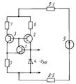
На чертеже представлена электрическая схема предлагаемого стабилизатора. The drawing shows an electrical diagram of the proposed stabilizer.
Стабилизатор содержит первый 1 биполярный транзистор одного типа проводимости, например n-p-n-типа, второй 2 и третий 3 биполярные транзисторы другого типа проводимости, например p-n-p-типа, опорный стабилитрон 4, первый 5, второй 6 и третий 7 резисторы, нагрузку 8-1 или 8-2 и источник 9 напряжения питания. The stabilizer contains the first 1 bipolar transistor of one type of conductivity, for example npn type, the second 2 and third 3 bipolar transistors of another type of conductivity, for example pnp type, a
Предложенный стабилизатор тока построен на базе транзисторного отражателя токов, выходной каскад которого реализован на втором транзисторе 2 и запитывает опорный стабилитрон 4. Входной каскад отражателя токов реализован на третьем транзисторе 3. Входные и выходные токи отражателя токов, образованные токами коллекторов соответственно третьего 3 и второго 2 транзисторов, связаны соотношением
Iк2=Iк3 ˙ R7/R6, где R6 и R7 - номиналы второго 6 и третьего 7 резисторов.The proposed current stabilizer is based on a transistor current reflector, the output stage of which is implemented on the
I k2 = I k3 ˙ R 7 / R 6 , where R 6 and R 7 are the values of the second 6 and third 7 resistors.
Первый транзистор 1, переход база-эмиттер которого замкнут в контуре опорного стабилитрона 4 и первого резистора 5, одновременно образует элемент сравнения и усиления и управляет суммой токов баз второго 2 и третьего 3 транзисторов. Входной ток Iк3 отражателя токов стабилизирован цепью отрицательной обратной связи с коллектора третьего транзистора 3 на эмиттер первого транзистора 1 примерным соотношением
Iк3=(Uо-Uбэ)/R5, где Uо - напряжение стабилизации стабилитрона 4;
Uбэ - напряжение перехода база-эмиттер первого транзистора 1;
R5 - номинал первого 5 резистора.The
I k3 = (U о -U бэ ) / R 5 , where U о is the stabilization voltage of the
U BE is the base-emitter junction voltage of the
R 5 is the face value of the first 5 resistor.
Стабилизатор работает следующим образом. The stabilizer works as follows.
При подаче напряжения питания с источника 9 любые изменения теплового тока второго транзистора 2 приводят к росту напряжения на выводах стабилитрона 4 и к росту токов коллекторов первого, третьего и второго транзисторов. В конечном счете на выводах стабилитрона 4 устанавливается напряжение, определяемое его напряжением стабилизации Uо. Надежность начального запуска стабилизатора обеспечена тем, что первый и третий транзисторы фактически образуют составной транзистор по схеме общий эмиттер - общий эмиттер с очень большим коэффициентом усиления тока базы первого транзистора.When applying a supply voltage from
Выходной ток в нагрузке 8-1 или 8-2 стабилен и определяется соотношением
Iн=(Uo-Uбэ) (R6+R7)/R5 R6.
С учетом конечных значений коэффициентов усиления β1, β2 ,и β3соответственно первого, второго и третьего транзисторов более точное значение Iн точн тока в нагрузке определяется как
Iн точн=Iн ˙ (1- γ), где γ - методическая погрешность
γ = ![]()
В опытном образце устройства на транзисторных сборках 1НТ 251 и 2ТС 622 и стабилитроне 2С 108 выходное сопротивление составляло 400 кОм при токе нагрузки 12 мА, а стабильность эталонного напряжения на выводах стабилитрона была приблизительно 1 мВ при напряжении питания источника 9 в пределах (15±3) В.The output current in the load 8-1 or 8-2 is stable and is determined by the ratio
I n = (U o -U be ) (R 6 + R 7 ) / R 5 R 6.
Given the finite values of the gain coefficients β 1, β 2 and β 3 respectively, first, second and third transistors a current value I n accurate load current is determined as
I n exact = I n ˙ (1- γ), where γ is the methodological error
γ = ![]()
In a prototype device on transistor assemblies 1НТ 251 and 2ТС 622 and a zener diode 2C 108, the output resistance was 400 kOhm at a load current of 12 mA, and the stability of the reference voltage at the zener diode terminals was approximately 1 mV with a supply voltage of
Claims (1)
Priority Applications (1)
| Application Number | Priority Date | Filing Date | Title |
|---|---|---|---|
| SU5019404 RU2024918C1 (en) | 1991-07-22 | 1991-07-22 | Direct current stabilizer |
Applications Claiming Priority (1)
| Application Number | Priority Date | Filing Date | Title |
|---|---|---|---|
| SU5019404 RU2024918C1 (en) | 1991-07-22 | 1991-07-22 | Direct current stabilizer |
Publications (1)
| Publication Number | Publication Date |
|---|---|
| RU2024918C1 true RU2024918C1 (en) | 1994-12-15 |
Family
ID=21592974
Family Applications (1)
| Application Number | Title | Priority Date | Filing Date |
|---|---|---|---|
| SU5019404 RU2024918C1 (en) | 1991-07-22 | 1991-07-22 | Direct current stabilizer |
Country Status (1)
| Country | Link |
|---|---|
| RU (1) | RU2024918C1 (en) |
-
1991
- 1991-07-22 RU SU5019404 patent/RU2024918C1/en active
Non-Patent Citations (5)
| Title |
|---|
| 1. Авторское свидетельство СССР N 521556, кл. G 05F 1/56, 1975. * |
| 2. Авторское свидетельство СССР N 1062669, кл. G 05F 1/56, 1983. * |
| 3. Авторское свидетельство СССР N 1256147, кл. G 05F 1/56, 1986. * |
| 4. Журнал "Электроники", N 25, 1982, с.63. * |
| 5. Авторское свидетельство СССР N 1309011, кл. G 05F 1/56, 1987. * |
Similar Documents
| Publication | Publication Date | Title |
|---|---|---|
| US7800430B2 (en) | Temperature-compensated current generator, for instance for 1-10V interfaces | |
| RU2024918C1 (en) | Direct current stabilizer | |
| US3536986A (en) | Low level costant current source | |
| KR870004555A (en) | Voltage regulator circuit | |
| RU2025766C1 (en) | Constantly controlled direct current stabilizer | |
| SU440657A1 (en) | Voltage stabilizer with bipolar output | |
| SU694853A2 (en) | Stabilized d -c current source | |
| RU2028657C1 (en) | Dc voltage stabilizer | |
| SU1665354A1 (en) | Dc voltage regulator of the compensation type | |
| SU890381A1 (en) | Dc stabilizer | |
| SU826314A1 (en) | Dc voltage stabilizer | |
| RU2079871C1 (en) | Voltage stabilizer | |
| SU1439559A1 (en) | D.c. voltage stabilizer | |
| SU1086417A1 (en) | Bipolar stabilized power source | |
| JPH0530184Y2 (en) | ||
| SU1100612A1 (en) | D.c.stabilizer | |
| SU1118988A1 (en) | D.c.stabilizer | |
| SU954982A1 (en) | Dc voltage stabilizer | |
| SU873225A1 (en) | Dc voltage stabilizer | |
| SU1665353A1 (en) | Dc voltage regulator of the compensation type | |
| SU427325A1 (en) | SEMICONDUCTOR STABILIZER | |
| US3345553A (en) | Stabilized direct current supply circuit | |
| KR920004322Y1 (en) | Constant current circuit | |
| SU1460715A1 (en) | Current stabilizer | |
| SU588537A1 (en) | Low dc voltage stabilizer |