RU2019373C1 - Shaped strip manufacturing method - Google Patents
Shaped strip manufacturing method Download PDFInfo
- Publication number
- RU2019373C1 RU2019373C1 SU5046516A RU2019373C1 RU 2019373 C1 RU2019373 C1 RU 2019373C1 SU 5046516 A SU5046516 A SU 5046516A RU 2019373 C1 RU2019373 C1 RU 2019373C1
- Authority
- RU
- Russia
- Prior art keywords
- profile
- shaped
- rolling
- tape
- strip
- Prior art date
Links
- 238000004519 manufacturing process Methods 0.000 title abstract description 5
- 238000005096 rolling process Methods 0.000 claims abstract description 22
- 238000000034 method Methods 0.000 claims abstract description 10
- 238000005452 bending Methods 0.000 claims abstract description 9
- 238000003466 welding Methods 0.000 claims abstract description 9
- 239000007858 starting material Substances 0.000 claims 2
- 230000015572 biosynthetic process Effects 0.000 claims 1
- 239000000463 material Substances 0.000 abstract description 9
- 239000002184 metal Substances 0.000 abstract description 4
- 229910052751 metal Inorganic materials 0.000 abstract description 4
- 238000005520 cutting process Methods 0.000 abstract description 2
- 230000000694 effects Effects 0.000 abstract 1
- 239000000126 substance Substances 0.000 abstract 1
- 239000000758 substrate Substances 0.000 description 6
- 239000011248 coating agent Substances 0.000 description 5
- 238000000576 coating method Methods 0.000 description 5
- 238000006073 displacement reaction Methods 0.000 description 3
- 229910001369 Brass Inorganic materials 0.000 description 2
- 239000010951 brass Substances 0.000 description 2
- 230000006835 compression Effects 0.000 description 2
- 238000007906 compression Methods 0.000 description 2
- 238000005253 cladding Methods 0.000 description 1
- 238000004140 cleaning Methods 0.000 description 1
- 238000005097 cold rolling Methods 0.000 description 1
- 238000010586 diagram Methods 0.000 description 1
- 238000004090 dissolution Methods 0.000 description 1
- 238000002474 experimental method Methods 0.000 description 1
- 238000005272 metallurgy Methods 0.000 description 1
- 238000002360 preparation method Methods 0.000 description 1
- 238000009966 trimming Methods 0.000 description 1
Images
Landscapes
- Metal Rolling (AREA)
Abstract
Description
Изобретение относится к производству профильных лент, используемых в электронной и других отраслях промышленности. The invention relates to the production of profile tapes used in electronic and other industries.
Известен способ частичного (полосчатого) плакирования металлических полос, согласно которому многослойную ленту получают холодной прокаткой на гладких валках из материала подложки с установленным на ней одной или несколькими располагаемыми на некотором расстоянии друг от друга параллельно линии прокатки полосами материала покрытия (Малышев В.М. и др. Золото, М.: Металлургия, 1979.). A known method of partial (banded) cladding of metal strips, according to which a multilayer tape is obtained by cold rolling on smooth rolls from a substrate material with one or more strips of coating material placed on it at a certain distance from each other parallel to the rolling line (V. Malyshev and other Gold, M .: Metallurgy, 1979.).
Недостатком этого решения является невозможность получения многослойных материалов с рельефным поперечным профилем, выступающим за поверхность подложки (основы). The disadvantage of this solution is the inability to obtain multilayer materials with a relief transverse profile protruding beyond the surface of the substrate (base).
Известен также способ получения профильных лент, согласно которому зачищают контактные поверхности двух лент, представляющих основу (подложку), а также лент материала покрытия, осуществляют сборку пакета. При этом подложки располагают одна над другой, а между ними размещают встык боковыми кромками параллельно линии прокатки ленты материала покрытия, осуществляют прокатку пакета, обеспечивающую сваривание лент основы с лентами материала подложки, после чего полученную заготовку разделяют на профильные ленты. В результате получают профильные ленты Г-образного сечения. There is also a method of producing profile tapes, according to which the contact surfaces of two tapes representing the base (substrate), as well as tapes of the coating material are cleaned, the package is assembled. In this case, the substrates are placed one on top of the other, and they are butt-welded between the side edges parallel to the rolling line of the coating material tape, the package is rolled, which welds the base tapes with the substrate material tapes, after which the resulting workpiece is divided into profile tapes. The result is a profile tape L-shaped section.
Недостатком способа является неустойчивость лент материала покрытия на основе, что может привести к смещению в поперечном направлении лент материала покрытия относительно основы. Это обстоятельство приводит к неисправному браку либо к значительным потерям металла, возникающим при обрези. The disadvantage of this method is the instability of the tapes of the coating material on the base, which can lead to a displacement in the transverse direction of the tapes of the coating material relative to the base. This circumstance leads to malfunctioning or to significant metal losses that occur during trimming.
Изобретение решает следующую техническую задачу - повышение качества ленты и экономии металла. The invention solves the following technical problem - improving the quality of the tape and saving metal.
Решение технической задачи достигается тем, что в способе изготовления профильной ленты преимущественно П и Г - образного сечений, включающем подготовку контактных поверхностей и сварку прокаткой, после подготовки поверхности ленты требуемый профиль ленты формируют путем изгиба краев ленты до контакта зачищенных поверхностей, при этом ширина загибаемого края ленты равна ширине утолщенного участка годового профиля. The solution to the technical problem is achieved by the fact that in the method of manufacturing a profile tape mainly P and G-shaped sections, including the preparation of contact surfaces and welding by rolling, after preparing the surface of the tape, the desired profile of the tape is formed by bending the edges of the tape until the contact of the cleaned surfaces, while the width of the bent edge the tape is equal to the width of the thickened section of the annual profile.
Для повышения производительности при производстве Г-образного профиля изгибом формируют П-образный профиль, а после прокатки осуществляют продольную резку. Кроме того, для решения данной технической задачи прокатку профильных заготовок осуществляют пакетным способом. To increase productivity in the production of the L-shaped profile, a U-shaped profile is formed by bending, and after rolling, longitudinal cutting is performed. In addition, to solve this technical problem, the rolling of profile billets is carried out in a batch manner.
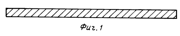
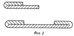
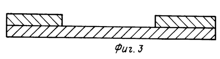
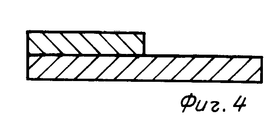
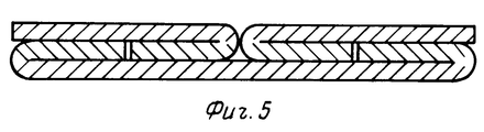
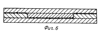
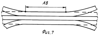
На фиг.1 изображена исходная заготовка, поперечное сечение; на фиг.2 - поперечное сечение заготовки после изгиба ее краев; на фиг. 3 - поперечное сечение профильной ленты после сварки прокаткой; на фиг. 4 - поперечное сечение профильной ленты Г-образного сечения после роспуска ленты П-образного сечения; на фиг. 5 - вариант сборки пакета из заготовок с П-образным и Г-образным поперечными сечениями; на фиг. 6 - поперечное сечение профильной ленты, полученной прокаткой по известному изобретению; на фиг. 7 - схема, поясняющая неравномерность деформации при сварке прокаткой. Figure 1 shows the original workpiece, a cross section; figure 2 is a cross section of the workpiece after bending its edges; in FIG. 3 - cross section of a profile tape after welding by rolling; in FIG. 4 is a cross section of a profile tape of an L-shaped section after the dissolution of a tape of a U-shaped section; in FIG. 5 is an embodiment of assembling a package of blanks with a U-shaped and an L-shaped cross-section; in FIG. 6 is a cross-sectional view of a profile strip obtained by rolling according to the known invention; in FIG. 7 is a diagram explaining the unevenness of deformation during rolling welding.
Способ осуществляют следующим образом. The method is as follows.
Одну поверхность исходной ленты (заготовки) прямоугольного поперечного сечения (фиг.1 ) зачищают. После зачистки кромки ленты загибают до контакта с зачищенной поверхностью ленты (фиг. 2). Затем осуществляют прокатку для сваривания контактирующих участков загнутой кромки и основы ленты. В результате получают профильную ленту (фиг.3). One surface of the original tape (blank) of rectangular cross-section (figure 1) is cleaned. After stripping, the edges of the tape are bent to contact with the stripped surface of the tape (Fig. 2). Then, rolling is carried out to weld the contacting sections of the bent edge and the base of the tape. The result is a profile tape (figure 3).
Для получения Г-образного профиля (фиг.2) с целью повышения производительности целесообразно изгибом кромок формировать П-образный профиль, а после сварки прокаткой осуществлять роспуск на 2 ленты Г-образного сечения (фиг.4). To obtain a L-shaped profile (figure 2) in order to increase productivity, it is advisable to form a U-shaped profile by bending the edges, and after welding rolling, dissolve into 2 tapes of the L-shaped section (figure 4).
Для повышения производительности и снижения затрат на подготовку валков целесообразно после формирования заготовок изгибом кромок собирать заготовки в пакет, например, как показано на фиг.5, после чего сварку прокаткой осуществлять пакетным способом на гладкой бочке валков. To increase productivity and reduce the cost of preparing the rolls, it is advisable, after forming the blanks by bending the edges, to assemble the blanks into a bag, for example, as shown in Fig. 5, after which rolling rolling is carried out in a batch manner on a smooth roll barrel.
Эффективность приема предлагаемого изобретения подтверждается опытными прокатками. На лабораторном стане с диаметром рабочих валков 180 мм получали профильные ленты согласно прототипу и предлагаемому изобретению. The effectiveness of the proposed invention is confirmed by experimental rolling. On a laboratory mill with a diameter of work rolls of 180 mm received profile tape according to the prototype and the invention.
В качестве исходной заготовки использовали ленту прямоугольного поперечного сечения из латуни Л 90 толщиной 1 мм и шириной 75 мм. Зачистку одной поверхности ленты осуществляли проволочными щетками. После изгиба кромок, каждая шириной 12,5 мм, профильная заготовка П-образного сечения имела ширину 50 мм. Сварку прокаткой осуществляли в валках с нарезанными на них калибрами, соответствующими профилю готовой ленты. Прокатку осуществляли без натяжений с относительным обжатием 50% всего сечения заготовки. В результате получили профильную ленту П-образного сечения шириной 50 мм, толщиной средней части 0,5 мм и толщиной кромок 1 мм. Профильная лента имела правильную геометрию и надежную сварку. As the initial preform, a rectangular cross-section tape of brass L 90 with a thickness of 1 mm and a width of 75 mm was used. The cleaning of one surface of the tape was carried out with wire brushes. After bending the edges, each 12.5 mm wide, the U-shaped profile blank had a width of 50 mm. Welding by rolling was carried out in rolls with gauges cut into them, corresponding to the profile of the finished tape. Rolling was carried out without tension with a relative compression of 50% of the entire cross section of the workpiece. As a result, a U-shaped profile tape was obtained with a width of 50 mm, a middle part with a thickness of 0.5 mm and an edge thickness of 1 mm. The profile tape had the correct geometry and reliable welding.
В соответствии с прототипом подготовили исходные ленты толщиной 1 мм из латуни Л-90. При этом две подложки были шириной по 50 мм, две ленты - шириной по 12,5 мм и одна лента шириной 25 мм. Все ленты зачищали с одной стороны. Сборку пакета осуществляли в соответствии с прототипом (фиг.6). На фиг. 6 волнистыми линиями показаны зачищенные поверхности. Прокатку пакета осуществляли на гладкой бочке с относительным обжатием 50%. В результате прокатки получим ленту длиной 500 мм. Причем средний участок (длиной 200 мм) имел удовлетворительное качество как по сварке компонентов, так и по геометрии, а передний и задний концы полосы (примерно по 100-150 мм) не сварились. Последнее произошло по причине смещения центральных полосок относительно основы. Смещение сопровождалось появлением неравномерных условий деформации по ширине и высоте полосы и, как следствие, изгибом компонентов в вертикальной и горизонтальной плоскостях (фиг. 7). In accordance with the prototype prepared the original tape with a thickness of 1 mm from brass L-90. In this case, two substrates were 50 mm wide, two tapes 12.5 mm wide, and one tape 25 mm wide. All tapes were stripped on one side. The assembly of the package was carried out in accordance with the prototype (Fig.6). In FIG. 6 wavy lines show the cleaned surface. Rolling the package was carried out on a smooth barrel with a relative compression of 50%. As a result of rolling, we get a tape 500 mm long. Moreover, the middle section (200 mm long) was of satisfactory quality both in welding components and in geometry, and the front and rear ends of the strip (approximately 100-150 mm) were not welded. The latter happened due to the displacement of the central strips relative to the base. The displacement was accompanied by the appearance of uneven deformation conditions along the width and height of the strip and, as a result, by the bending of the components in the vertical and horizontal planes (Fig. 7).
Качественный участок АВ (фиг.7) ленты распускали (разрезали) в продольном направлении на две половины и после разборки пакета получали 4 ленты Г-образного сечения. A high-quality section AB (Fig. 7), the ribbons were dissolved (cut) in two longitudinal directions into two halves, and after the package was disassembled, 4 tapes of an L-shaped section were obtained.
Таким образом, предлагаемый способ по сравнению с прототипом за счет устойчивого положения компонентов обеспечивает повышение качества и выход годного, как показывают опыты, более, чем в два раза. Thus, the proposed method in comparison with the prototype due to the stable position of the components provides improved quality and yield, as shown by experiments, more than doubled.
Claims (2)
Priority Applications (1)
| Application Number | Priority Date | Filing Date | Title |
|---|---|---|---|
| SU5046516 RU2019373C1 (en) | 1992-06-08 | 1992-06-08 | Shaped strip manufacturing method |
Applications Claiming Priority (1)
| Application Number | Priority Date | Filing Date | Title |
|---|---|---|---|
| SU5046516 RU2019373C1 (en) | 1992-06-08 | 1992-06-08 | Shaped strip manufacturing method |
Publications (1)
| Publication Number | Publication Date |
|---|---|
| RU2019373C1 true RU2019373C1 (en) | 1994-09-15 |
Family
ID=21606408
Family Applications (1)
| Application Number | Title | Priority Date | Filing Date |
|---|---|---|---|
| SU5046516 RU2019373C1 (en) | 1992-06-08 | 1992-06-08 | Shaped strip manufacturing method |
Country Status (1)
| Country | Link |
|---|---|
| RU (1) | RU2019373C1 (en) |
-
1992
- 1992-06-08 RU SU5046516 patent/RU2019373C1/en active
Non-Patent Citations (1)
| Title |
|---|
| Авторское свидетельство СССР N 593887, B 23K 20/04, опублик.1978. * |
Similar Documents
| Publication | Publication Date | Title |
|---|---|---|
| JPH0390202A (en) | Manufacture of deformed cross section strip sheet | |
| RU2019373C1 (en) | Shaped strip manufacturing method | |
| JPH07100528A (en) | Production of special shaped tube excellent in shape property | |
| RU2056245C1 (en) | Wire manufacturing method | |
| RU2068324C1 (en) | Bimetal strip, for instance for welded pipes, and bimetal strip manufacture method | |
| CN210754352U (en) | Hot-rolled strip steel endless rolling intermediate billet connecting system | |
| JPH01241302A (en) | Manufacture of titanium wire for electrode | |
| JP2836361B2 (en) | Manufacturing method of irregular cross section | |
| JPH03193232A (en) | Manufacturing method for irregular cross-section strips | |
| JP2721248B2 (en) | Manufacturing method of composite contact strip | |
| CN216894082U (en) | Spacing strip, door and window | |
| JPH06154802A (en) | Manufacture of angle bar | |
| JPH0150502B2 (en) | ||
| JPH06154933A (en) | Manufacture of angle material | |
| JP3258143B2 (en) | Manufacturing method of irregular cross section | |
| JPH0484603A (en) | Manufacture of band plate with special shaped section | |
| JPS61137625A (en) | Production of square steel pipe | |
| JPS60199523A (en) | Manufacture of square tube | |
| JPH0438516B2 (en) | ||
| JP2504791B2 (en) | Tape material manufacturing method | |
| JP2788911B2 (en) | Manufacturing method of thin wall ERW pipe | |
| JPH08294723A (en) | Production of multilayered tube with using different kind metal and heat insulating material | |
| JPH0370576B2 (en) | ||
| JPS62173043A (en) | Manufacture of piston ring | |
| JPH0338032B2 (en) |