RU2016373C1 - Position measuring device - Google Patents
Position measuring device Download PDFInfo
- Publication number
- RU2016373C1 RU2016373C1 SU4875242A RU2016373C1 RU 2016373 C1 RU2016373 C1 RU 2016373C1 SU 4875242 A SU4875242 A SU 4875242A RU 2016373 C1 RU2016373 C1 RU 2016373C1
- Authority
- RU
- Russia
- Prior art keywords
- magnetoresistors
- bridge
- magnetic field
- permanent magnet
- field source
- Prior art date
Links
Images

Landscapes
- Measurement Of Length, Angles, Or The Like Using Electric Or Magnetic Means (AREA)
- Measuring Magnetic Variables (AREA)
Abstract
Description
Изобретение относится к измерительной технике и может быть использовано для контроля положения различных объектов, например в системах управления автоматическими линиями или в промышленных роботах. The invention relates to measuring equipment and can be used to control the position of various objects, for example in control systems for automatic lines or in industrial robots.
Известны гальваномагнитные датчики положения, основанные на использовании элементов Холла, которые однако обладают значительной температурной зависимостью чувствительности и внутреннего сопротивления, что снижает их точность [1]. Known galvanomagnetic position sensors based on the use of Hall elements, which however have a significant temperature dependence of sensitivity and internal resistance, which reduces their accuracy [1].
Ближайшим техническим решением к изобретению является устройство для контроля положения, содержащее источник постоянного магнитного поля, установленный с возможностью перемещения, магниторезистивный датчик, выполненный в виде четырех магниторезисторов, имеющих форму плоских меандров, размещенных на общей диэлектрической подложке и включенных в плечи измерительного моста, подключенный к одной диагонали моста источник питания постоянного тока и подключенный к другой его диагонали блок обработки сигналов [2] . Недостатком этого устройства является невысокая помехоустойчивость, поскольку магниторезисторы мостовой схемы одинаково реагируют как на полезный сигнал, так и на помеху, что в условиях сильных помех может привести к ложным срабатываниям датчика. Кроме того, используемые в этом устройстве полупроводниковые магниторезисторы обладают невысокой термостабильностью. The closest technical solution to the invention is a position monitoring device containing a constant magnetic field source mounted for displacement, a magnetoresistive sensor made in the form of four magnetoresistors in the form of flat meanders placed on a common dielectric substrate and included in the arms of the measuring bridge connected to one diagonal of the bridge has a DC power source and a signal processing unit connected to its other diagonal [2]. The disadvantage of this device is the low noise immunity, since the magnetoresistors of the bridge circuit respond equally to both a useful signal and interference, which in the presence of strong interference can lead to false responses of the sensor. In addition, the semiconductor magnetoresistors used in this device have low thermal stability.
Целью изобретения является повышение помехоустойчивости и температурной стабильности устройства для контроля положения. The aim of the invention is to increase the noise immunity and temperature stability of the device for position control.
Для достижения цели в устройстве для контроля положения, содержащем источник постоянного магнитного поля, установленный с возможностью перемещения, магниторезистивный датчик, выполненный в виде четырех магниторезисторов, имеющих форму плоских меандров, размещенных на общей диэлектрической подложке и включенных в плечи измерительного моста, подключенный к одной диагонали моста источник питания постоянного тока и подключенный к другой его диагонали блок обработки сигналов, магниторезисторы выполнены из пермаллоевой пленки, источник магнитного поля размещен в общей плоскости с подложкой, магниторезисторы хотя бы в одной из ветвей моста размещены на расстоянии один от другого, выбираемом в зависимости от их габаритных размеров и магнитных параметров пленки и источника магнитного поля, а блок обработки сигналов выполнен в виде пороговой схемы. Кроме того, магниторезисторы, включенные во вторую ветвь моста, могут быть расположены перпедикулярно к магниторезисторам первой ветви, а присоединенные к одному и тому же полюсу источника питания магниторезисторы могут быть размещены парами в непосредственной близости один от другого. To achieve the goal in a position monitoring device containing a constant magnetic field source mounted for displacement, a magnetoresistive sensor made in the form of four magnetoresistors in the form of flat meanders placed on a common dielectric substrate and included in the arms of the measuring bridge connected to one diagonal DC power supply and signal processing unit connected to its other diagonal, magnetoresistors made of permalloy film, source the magnetic field is placed in a common plane with the substrate, the magnetoresistors in at least one of the bridge branches are located at a distance from each other, selected depending on their overall dimensions and the magnetic parameters of the film and the magnetic field source, and the signal processing unit is designed as a threshold circuit. In addition, the magnetoresistors included in the second branch of the bridge can be perpendicular to the magnetoresistors of the first branch, and the magnetoresistors connected to the same pole of the power supply can be placed in pairs in close proximity to one another.
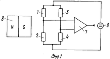
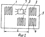
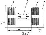
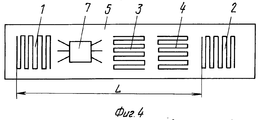
На фиг. 1 изображена схема устройства для контроля положения; на фиг. 2-5 схематически показаны варианты размещения магниторезисторов на общей диэлектрической подложке. In FIG. 1 shows a diagram of a device for monitoring position; in FIG. 2-5 schematically show the arrangement of magnetoresistors on a common dielectric substrate.
Устройство содержит четыре магниторезистора 1-4, размещенные на общей диэлектрической подложке 5 и включенные в плечи измерительного моста. К одной диагонали моста подключен источник 6 питания постоянного тока, а к другой его диагонали присоединен блок 7 обработки его сигналов. Магниторезисторы выполнены из пермаллоевой пленки в виде плоских меандров, а источник магнитного поля - постоянный магнит 8 расположен в общей плоскости с подложкой 5, на которой размещены магниторезисторы. Магнит 8 закрепляется на объекте контроля в процессе измерений. The device contains four magnetoresistors 1-4, placed on a common
Магниторезисторы хотя бы в одной из ветвей моста, например 1 и 2, ориентированы одинаково относительно магнита 8 и расположены на расстоянии L один от другого, выбираемом в зависимости от их габаритных размеров и магнитных параметров пленки и источника магнитного поля. Magnetoresistors in at least one of the bridge branches, for example 1 and 2, are oriented identically with respect to
В варианте исполнения магниторезисторы 3 и 4 второй пары, могут быть расположены идентично положению магниторезисторов первой пары (фиг. 3). В другом варианте исполнения магниторезисторы 3 и 4 второй пары могут быть ориентированы перпендикулярно относительно магниторезисторов первой пары (фиг. 4), что ослабляет их чувствительность к воздействию источника магнитного поля. Наиболее предпочтительным вариантом с точки зрения повышения температурной стабильности устройства является вариант, в котором присоединенные к одному и тому же полюсу источника 6 питания магниторезисторы, например 1, 3 и 2, 4 (фиг. 5), размещены парами в непосредственной близости один от другого. In an embodiment, the
Устройство для контроля положения работает следующим образом. A device for monitoring position works as follows.
При отсутствии источника 8 в его регистрируемом положении мостовая схема сбалансирована и ее выходное напряжение равно нулю. В зависимости от конкретного использования устройства на выходе блока 7 формируется выходной сигнал. При воздействии магнитного поля помехи, которое создается чаще всего удаленным и геометрически протяженным (в сравнении с геометрическими размерами датчика) источником, помеха не вызывает разбаланса моста, одинаково воздействует на оба магниторезистора каждой ветви моста. In the absence of
При появлении источника 8 в его детектируемом положении под воздействием создаваемого им магнитного поля изменяется величина сопротивления магниторезистора 1, а величина сопротивления магниторезистора 2 остается практически без изменения, так как этот магниторезистор смещен на расстояние L от магниторезистора 1. Величины сопротивлений магниторезисторов 3 и 4 изменяются одинаково, не влияя на разбаланс моста, а в случае поворота на 90о (фиг. 4) не изменяются вовсе. Появившееся напряжение разбаланса мостовой схемы подается на блок 7, а затем на внешнее регистрирующее или исполнительное устройство.When the
Claims (3)
Priority Applications (1)
| Application Number | Priority Date | Filing Date | Title |
|---|---|---|---|
| SU4875242 RU2016373C1 (en) | 1990-10-16 | 1990-10-16 | Position measuring device |
Applications Claiming Priority (1)
| Application Number | Priority Date | Filing Date | Title |
|---|---|---|---|
| SU4875242 RU2016373C1 (en) | 1990-10-16 | 1990-10-16 | Position measuring device |
Publications (1)
| Publication Number | Publication Date |
|---|---|
| RU2016373C1 true RU2016373C1 (en) | 1994-07-15 |
Family
ID=21541134
Family Applications (1)
| Application Number | Title | Priority Date | Filing Date |
|---|---|---|---|
| SU4875242 RU2016373C1 (en) | 1990-10-16 | 1990-10-16 | Position measuring device |
Country Status (1)
| Country | Link |
|---|---|
| RU (1) | RU2016373C1 (en) |
Cited By (1)
| Publication number | Priority date | Publication date | Assignee | Title |
|---|---|---|---|---|
| RU2553740C1 (en) * | 2014-03-25 | 2015-06-20 | Федеральное государственное бюджетное образовательное учреждение высшего профессионального образования "Уфимский государственный авиационный технический университет" | Method for improvement of sensitivity parameter of magnetoresistive sensors |
-
1990
- 1990-10-16 RU SU4875242 patent/RU2016373C1/en active
Non-Patent Citations (2)
| Title |
|---|
| 1. Хомерики О.К. Гальваномагнитные элементы устройств автоматики и вычислительной техники. М.: Энергия, 1975, с.174. * |
| 2. Авторское свидетельство СССР N 1027657, кл. G 01R 33/06, 1981. * |
Cited By (1)
| Publication number | Priority date | Publication date | Assignee | Title |
|---|---|---|---|---|
| RU2553740C1 (en) * | 2014-03-25 | 2015-06-20 | Федеральное государственное бюджетное образовательное учреждение высшего профессионального образования "Уфимский государственный авиационный технический университет" | Method for improvement of sensitivity parameter of magnetoresistive sensors |
Similar Documents
| Publication | Publication Date | Title |
|---|---|---|
| US5477143A (en) | Sensor with magnetoresistors disposed on a plane which is parallel to and displaced from the magnetic axis of a permanent magnet | |
| JP3028377B2 (en) | Magnetoresistive proximity sensor | |
| US6304078B1 (en) | Linear position sensor | |
| US5610518A (en) | Method and apparatus for detecting small magnetizable particles and flaws in nonmagnetic conductors | |
| US5497082A (en) | Quadrature detector with a hall effect element and a magnetoresistive element | |
| DE60139017D1 (en) | THIN FILM MAGNETIC SENSOR | |
| ATE322670T1 (en) | MEASUREMENT OF VOLTAGE IN A FERROMAGNETIC MATERIAL | |
| CN113917216A (en) | Current measuring device | |
| US4255708A (en) | Magnetoresistive position transducer with invariable peak signal | |
| RU2016373C1 (en) | Position measuring device | |
| CN115900773B (en) | Magnetic position sensor systems | |
| US12146928B2 (en) | Magnetic field sensor with overcurrent detection | |
| US12078695B2 (en) | Magnetic field sensor with overcurrent detection | |
| US7019607B2 (en) | Precision non-contact digital switch | |
| JP2005257642A (en) | Magnetic detection circuit and encoder | |
| RU202681U1 (en) | MAGNETIC STRUCTUROSCOPE | |
| SU1516745A1 (en) | Galvanometric device for measuring displacements | |
| RU2216822C1 (en) | Magnetoresistive pickup | |
| SU386353A1 (en) | DEVICE FOR MEASURING COERTSITIVE FORCE-POWERED MAGNETS | |
| JPH02194316A (en) | Displacement detecting device | |
| RU97113301A (en) | DEVICE FOR LOCAL MEASUREMENT OF FERROMAGNETIC PHASE OF AUSTENITIC STEELS | |
| RU2152046C1 (en) | Method reducing effect of hysteresis on results of measurement of magnetic field | |
| JPH04271425A (en) | Contactless position detector | |
| JPH02136773A (en) | Magnetic sensor | |
| KR900000980B1 (en) | Angle measuring device and pattern forming method using magnetoresistive element |