RU2016332C1 - Electromagnetic valve - Google Patents
Electromagnetic valve Download PDFInfo
- Publication number
- RU2016332C1 RU2016332C1 SU5042142A RU2016332C1 RU 2016332 C1 RU2016332 C1 RU 2016332C1 SU 5042142 A SU5042142 A SU 5042142A RU 2016332 C1 RU2016332 C1 RU 2016332C1
- Authority
- RU
- Russia
- Prior art keywords
- shutter
- saddle
- seat
- valve
- armature
- Prior art date
Links
Images
Landscapes
- Magnetically Actuated Valves (AREA)
Abstract
Description
Изобретение относится к трубопроводной арматуре и может быть применено в качестве перекрывающих клапанов во всех областях промышленности и в машиностроении. The invention relates to valves and can be used as shutoff valves in all industries and in mechanical engineering.
Известен электромагнитный клапан, содержащий электрмагнит, якорь которого соединен с размещенным в корпусе затвором. Принцип действия такого электромагнитного клапана основан на перемещении затвора якорем электромагнита, который, в свою очередь, перемещается к стопу под действием сил притяжения, возбуждаемых магнитным потоком, возникающим в обмотке электромагнита [1]. A known electromagnetic valve containing an electromagnet, the anchor of which is connected to a shutter located in the housing. The principle of operation of such an electromagnetic valve is based on the movement of the shutter by the armature of an electromagnet, which, in turn, moves to the foot under the action of attractive forces excited by magnetic flux arising in the winding of the electromagnet [1].
Наиболее близким по технической сущности является электромагнитный клапан, содержащий корпус с седлом, толкающий электромагнит с магнитопроводом, магнитно-твердой вставкой и подпружиненным от седла якорем, и затвор. Это позволяет после прекращения импульса тока удерживать якорь у стопа без потребления электроэнергии с помощью магнитного потока, создаваемого магнитно-твердой вставкой [2]. The closest in technical essence is an electromagnetic valve containing a housing with a seat, a pushing electromagnet with a magnetic circuit, a magnetically solid insert and an anchor spring-loaded from the saddle, and a shutter. This allows, after the termination of the current pulse, to hold the anchor at the foot without consuming electricity using the magnetic flux generated by the magnetically solid insert [2].
Недостатками такого электромагнитного клапана являются большая масса, габариты и энергопотребление из-за недостаточно эффективного использования энергии электромагнитного привода. The disadvantages of such an electromagnetic valve are the large mass, dimensions and power consumption due to the insufficiently efficient use of the energy of the electromagnetic actuator.
Задачей, на решение которой направлено предлагаемое изобретение, является уменьшение габаритов и массы клапана, уменьшение энергопотребления, повышение надежности и долговечности, расширение функциональных возможностей. The problem to which the invention is directed, is to reduce the size and weight of the valve, reduce power consumption, increase reliability and durability, expand functionality.
Отличием предлагаемого клапана является то, что клапан снабжен дополнительной пружиной, установленной между якорем и затвором и нагружающей затвор в сторону седла, усилие удержания, развиваемое магнитно-твердой вставкой, больше суммы усилий основной и дополнительной пружин, затвор снабжен кольцевым осесимметричным выступом, направленным в сторону седла, и между внутренней поверхностью отверстия в выступе и наружной поверхностью седла выполнен калиброванный зазор, а элементы клапана выполнены с соблюдением следующих соотношений:
hя ≥ hпр + 0,20 dc; dз ≥ 1,35 dc;
hпр = (0,10...0,95) hя, hc>hв, где hя - полный ход якоря электромагнита;
dc - внутренний диаметр седла клапан;
dc - наружный диаметр затвора;
hпр - ход дополнительной пружины;
hс - высота седла;
hв - высота выступа на затворе.The difference of the proposed valve is that the valve is equipped with an additional spring installed between the armature and the bolt and loading the bolt towards the seat, the holding force developed by the magnetically hard insert is greater than the sum of the efforts of the main and additional springs, the bolt is equipped with an axisymmetric protrusion directed to the side the seat, and between the inner surface of the hole in the protrusion and the outer surface of the saddle a calibrated gap is made, and the valve elements are made in compliance with the following ratios:
h i ≥ h pr + 0.20 d c ; d s ≥ 1.35 d c ;
h CR = (0.10 ... 0.95) h i , h c > h in , where h i - full stroke of the armature of the electromagnet;
d c is the inner diameter of the valve seat;
d c is the outer diameter of the shutter;
h CR - the course of the additional spring;
h with - the height of the saddle;
h in - the height of the protrusion on the shutter.
Сущность изобретения является то, что затвор, подпружиненный дополнительной пружиной в сторону седла, более долговечен, а так как в начальный момент движения якоря на открытие усилия основной и дополнительной пружин суммируются друг с другом, то это позволяет якорю на расстоянии хода дополнительной пружины накопить большую кинетическую энергию для "срыва" затвора. Перечисленные отличия позволяют уменьшить массу, габариты и энергопотребление клапана, повысить его надежность и долговечность, расширить функциональные возможности. The essence of the invention is that the bolt, spring-loaded by an additional spring towards the seat, is more durable, and since at the initial moment of movement of the armature to open the efforts of the main and additional springs are summed with each other, this allows the armature to accumulate a large kinetic distance energy to "break" the shutter. These differences can reduce the weight, dimensions and power consumption of the valve, increase its reliability and durability, expand the functionality.
Дополнительное улучшение характеристик клапана достигается тем, что в момент "срыва" затвора вокруг наружной поверхности седла образуется кольцевой зазор с помощью выступа, направленного в сторону седла. Поток жидкости или газа после движения по кольцевому зазору при проходе через седло поворачивается почти на 180о, что увеличивает силу воздействия потока на затвор в сторону его открытия.An additional improvement in the valve characteristics is achieved by the fact that at the moment of “stalling” of the shutter an annular gap is formed around the outer surface of the seat with a protrusion directed towards the seat. The fluid flow after the movement of the annulus during passage through the saddle is rotated by almost 180 °, which increases the impact force on the flow valve towards its opening.
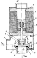
На чертеже изображена конструктивная схема электромагнитного клапана. The drawing shows a structural diagram of a solenoid valve.
Клапан содержит корпус 1 с седлом 2, входным 3 и выходным 4 патрубками. Затвор 5 прижимается к седлу дополнительной пружиной 6 и разностью входного и выходного давлений среды. На корпусе установлен электромагнит 7 с магнитно-твердой вставкой 8 и якорем 9, подпружиненным от седла пружиной 10. Затвор снабжен кольцевым выступом 11. К якорю прикреплен шток с упорным буртиком 12. The valve comprises a
Работает клапан следующим образом. The valve operates as follows.
При подаче кратковременного импульса напряжения определенной полярности на катушку электромагнита 7 якорь 9 перемещается к стопу, сжимая основную 10 и дополнительную 6 пружины. Воздушный зазор между якорем и стопом при этом уменьшается и усилие электромагнита возрастает. После подхода якоря к стопу импульс напряжения прекращается и якорь удерживается у стопа неограниченно долго без потребления энергии с помощью магнитного потока, создаваемого магнитно-твердой вставкой. Обратный ход происходит после подачи импульса напряжения противоположной полярности на катушку электромагнита 7. При этом вначале начинает двигаться якорь под воздействием основной и дополнительной пружин. При этом происходит накопление кинетической энергии якоря. Когда якорь проходит расстояние hпр зазор между буртиком 12 и поверхностью, на которую он воздействует, становится равным нулю, выпуклая поверхность буртика 12 производит удар и кинетическая энергия якоря передается затвору. Соударяющиеся поверхности выполняются упругими и выпуклыми для более полной передачи кинетической энергии при ударе.When applying a short-term voltage pulse of a certain polarity to the coil of the
Для накопления достаточной энергии для удара выдерживаются соотношения:
hпр = (0,10...0,95) hя
hя ≥ hпр + 0,20 dс
Кинетическая энергия якоря расходуется затем на необходимую для перемещения затвора работу, которая должна быть как можно меньше, что достигается увеличением крутизны падения гидравлической характеристики затвора по мере его удаления от седла. Для обеспечения достаточной крутизны гидравлической характеристики выдерживаются соотношения между диаметрами затвора и седла в виде: dз ≥ 1,35 dc, а также вокруг наружной поверхности седла с помощью кольцевого выступа на затворе образуется кольцевой зазор, позволяющий увеличить угол поворота потока среды при проходе его через седло, что увеличивает силу воздействия потока на затвор в сторону его открытия.To accumulate sufficient energy for the impact, the following ratios are maintained:
h ol = (0.10 ... 0.95) h i
h i ≥ h pr + 0.20 d s
The kinetic energy of the armature is then spent on the work necessary to move the shutter, which should be as small as possible, which is achieved by increasing the steepness of the hydraulic drop of the shutter as it moves away from the saddle. In order to ensure sufficient steepness of the hydraulic characteristic, the ratios between the shutter and seat diameters are maintained in the form of: d z ≥ 1.35 d c , and also around the outer surface of the saddle with the help of an annular protrusion, an annular gap is formed on the shutter, which allows increasing the angle of rotation of the medium flow when it passes through the saddle, which increases the force of the flow on the shutter in the direction of its opening.
Проведенные эксперименты показали, что предлагаемое решение позволяет улучшить характеристики клапана. Например, в одной из экспериментальных конструкций при неизмененных Pу и Dу масса электромагнита была уменьшена с 10 до 5 кг, т.е. в 2 раза, его мощность, была уменьшена с 800 до 160 Вт, т. е. в 5 раз, следовательно, общее улучшение параметров составило 10 раз. Если это необходимо, можно частично улучшить все параметры или провести улучшение одного, наиболее важного в данном случае параметра.The experiments showed that the proposed solution can improve the characteristics of the valve. For example, in one of the experimental designs with unchanged P y and D y, the mass of the electromagnet was reduced from 10 to 5 kg, i.e. 2 times, its power was reduced from 800 to 160 W, i.e. 5 times, therefore, the overall improvement of the parameters was 10 times. If necessary, it is possible to partially improve all the parameters or to improve one of the most important parameters in this case.
Следует отметить, что особенно большой эффект может быть получен от применения предложенного изобретения в мембранных и поршневых клапанах непрямого действия с подвижным разгрузочным седлом при больших диаметрах основного затвора. It should be noted that a particularly large effect can be obtained from the application of the proposed invention in membrane and piston valves of indirect action with a movable unloading seat with large diameters of the main shutter.
Таким образом, данное изобретение позволяет значительно уменьшить потребляемую мощность, массу и габариты электромагнита, расширить функциональные возможности, диапазон рабочих давлений, диаметров трубопроводов и температур рабочей и окружающей сред, повысить коэффициент запаса по усилиям и уменьшить массу подвижных деталей, тем самым повысив надежность электромагнитного клапана. Thus, this invention can significantly reduce the power consumption, mass and dimensions of the electromagnet, expand the functionality, range of operating pressures, pipe diameters and operating and ambient temperatures, increase the safety factor in efforts and reduce the mass of moving parts, thereby increasing the reliability of the electromagnetic valve .
Claims (1)
hя ≥ hпр + 0,20dс;
dз ≥ 1,35dс;
hпр = (0,10...0,95)hя;
hс > hв,
где hя - полный ход якоря электромагнита;
dс - внутренний диаметр седла клапана;
dз - наружный диаметр затвора;
hпр - ход дополнительной пружины;
hс - высота седла;
hв - высота выступа на затворе.ELECTROMAGNETIC VALVE, comprising a housing with a saddle, pushing an electromagnet with a magnetic circuit, a magnetically solid insert and an anchor spring-loaded from the saddle, and a shutter, characterized in that the valve is equipped with an additional spring installed between the armature and the shutter and loading the bolt towards the saddle, with this force retention, developed by a magnetically hard insert, is greater than the sum of the efforts of the main and additional springs, the shutter is equipped with an axisymmetric protrusion directed toward the saddle with the formation of a calibrated gap and between the inner surface of the protrusion and the outer surface of the seat, wherein the valve elements are made with the following proportions:
h i ≥ h pr + 0.20d s ;
d with s ≥ 1,35d;
h ol = (0.10 ... 0.95) h i ;
h c > h in ,
where h i - full stroke of the armature of the electromagnet;
d with - the inner diameter of the valve seat;
d s - the outer diameter of the shutter;
h CR - the course of the additional spring;
h with - the height of the saddle;
h in - the height of the protrusion on the shutter.
Priority Applications (1)
| Application Number | Priority Date | Filing Date | Title |
|---|---|---|---|
| SU5042142 RU2016332C1 (en) | 1992-05-12 | 1992-05-12 | Electromagnetic valve |
Applications Claiming Priority (1)
| Application Number | Priority Date | Filing Date | Title |
|---|---|---|---|
| SU5042142 RU2016332C1 (en) | 1992-05-12 | 1992-05-12 | Electromagnetic valve |
Publications (1)
| Publication Number | Publication Date |
|---|---|
| RU2016332C1 true RU2016332C1 (en) | 1994-07-15 |
Family
ID=21604205
Family Applications (1)
| Application Number | Title | Priority Date | Filing Date |
|---|---|---|---|
| SU5042142 RU2016332C1 (en) | 1992-05-12 | 1992-05-12 | Electromagnetic valve |
Country Status (1)
| Country | Link |
|---|---|
| RU (1) | RU2016332C1 (en) |
-
1992
- 1992-05-12 RU SU5042142 patent/RU2016332C1/en active
Non-Patent Citations (2)
| Title |
|---|
| 1. Пржиалковский А.Л., Щучинский С.Х. Электромагнитные клапаны. - Л.: Энергоатомиздат, 1967, с.20, рис.4. * |
| 2. Кармугин Б.В., Кисель В.Л., Лазебник А.Г. Современные конструкции малогабаритной пневмоарматуры. - Киев: Техника, 1980, с.163, рис.30в. * |
Similar Documents
| Publication | Publication Date | Title |
|---|---|---|
| US3043336A (en) | Solenoid valve | |
| US5139224A (en) | Solenoid armature bounce eliminator | |
| US3383084A (en) | Pulse-actuated valve | |
| US7651069B2 (en) | Electromagnetic actuators | |
| EP0903472B1 (en) | Electromagnetically driven valve for an internal combustion engine | |
| CA2400985A1 (en) | Permanent magnet actuator mechanism | |
| US4449691A (en) | Electromagnet | |
| CN101663523A (en) | Solenoid valve having a two piece moving valve element | |
| JPH1089194A (en) | Valve for fuel injection system | |
| RU2016332C1 (en) | Electromagnetic valve | |
| RU2016331C1 (en) | Electromagnetic valve | |
| US3988706A (en) | Solenoid actuating mechanism with variable rate energy storing means | |
| RU2016333C1 (en) | Electromagnetic valve | |
| US1879165A (en) | Electromagnetically-operated valve | |
| RU2011096C1 (en) | Electromagnetic valve | |
| EP1029332A1 (en) | Cascading electromagnetic armature | |
| CN107191661B (en) | Stop valve | |
| SU1687988A1 (en) | Electromagnetic valve | |
| RU2059140C1 (en) | Electromagnetic valve | |
| SU422910A1 (en) | STOP VALVE | |
| RU2020354C1 (en) | Solenoid-operated valve | |
| GB2062175A (en) | Solenoid-operated valve | |
| EP3667057B1 (en) | Fluid injector with a bistable spring element | |
| SU246991A1 (en) | VALVE WITH ELECTROMAGNETIC DRIVE | |
| DE4334350A1 (en) | Electromagnetically operated valve with a permanent magnet |