EP0903472B1 - Electromagnetically driven valve for an internal combustion engine - Google Patents
Electromagnetically driven valve for an internal combustion engine Download PDFInfo
- Publication number
- EP0903472B1 EP0903472B1 EP98113408A EP98113408A EP0903472B1 EP 0903472 B1 EP0903472 B1 EP 0903472B1 EP 98113408 A EP98113408 A EP 98113408A EP 98113408 A EP98113408 A EP 98113408A EP 0903472 B1 EP0903472 B1 EP 0903472B1
- Authority
- EP
- European Patent Office
- Prior art keywords
- armature
- core
- valve
- electromagnetically driven
- valve body
- Prior art date
- Legal status (The legal status is an assumption and is not a legal conclusion. Google has not performed a legal analysis and makes no representation as to the accuracy of the status listed.)
- Revoked
Links
Images
Classifications
-
- H—ELECTRICITY
- H01—ELECTRIC ELEMENTS
- H01F—MAGNETS; INDUCTANCES; TRANSFORMERS; SELECTION OF MATERIALS FOR THEIR MAGNETIC PROPERTIES
- H01F7/00—Magnets
- H01F7/06—Electromagnets; Actuators including electromagnets
- H01F7/08—Electromagnets; Actuators including electromagnets with armatures
- H01F7/16—Rectilinearly-movable armatures
- H01F7/1638—Armatures not entering the winding
-
- F—MECHANICAL ENGINEERING; LIGHTING; HEATING; WEAPONS; BLASTING
- F01—MACHINES OR ENGINES IN GENERAL; ENGINE PLANTS IN GENERAL; STEAM ENGINES
- F01L—CYCLICALLY OPERATING VALVES FOR MACHINES OR ENGINES
- F01L9/00—Valve-gear or valve arrangements actuated non-mechanically
- F01L9/20—Valve-gear or valve arrangements actuated non-mechanically by electric means
-
- F—MECHANICAL ENGINEERING; LIGHTING; HEATING; WEAPONS; BLASTING
- F16—ENGINEERING ELEMENTS AND UNITS; GENERAL MEASURES FOR PRODUCING AND MAINTAINING EFFECTIVE FUNCTIONING OF MACHINES OR INSTALLATIONS; THERMAL INSULATION IN GENERAL
- F16K—VALVES; TAPS; COCKS; ACTUATING-FLOATS; DEVICES FOR VENTING OR AERATING
- F16K31/00—Actuating devices; Operating means; Releasing devices
- F16K31/02—Actuating devices; Operating means; Releasing devices electric; magnetic
- F16K31/06—Actuating devices; Operating means; Releasing devices electric; magnetic using a magnet, e.g. diaphragm valves, cutting off by means of a liquid
-
- F—MECHANICAL ENGINEERING; LIGHTING; HEATING; WEAPONS; BLASTING
- F01—MACHINES OR ENGINES IN GENERAL; ENGINE PLANTS IN GENERAL; STEAM ENGINES
- F01L—CYCLICALLY OPERATING VALVES FOR MACHINES OR ENGINES
- F01L9/00—Valve-gear or valve arrangements actuated non-mechanically
- F01L9/20—Valve-gear or valve arrangements actuated non-mechanically by electric means
- F01L9/21—Valve-gear or valve arrangements actuated non-mechanically by electric means actuated by solenoids
- F01L2009/2132—Biasing means
- F01L2009/2134—Helical springs
- F01L2009/2136—Two opposed springs for intermediate resting position of the armature
-
- H—ELECTRICITY
- H01—ELECTRIC ELEMENTS
- H01F—MAGNETS; INDUCTANCES; TRANSFORMERS; SELECTION OF MATERIALS FOR THEIR MAGNETIC PROPERTIES
- H01F7/00—Magnets
- H01F7/06—Electromagnets; Actuators including electromagnets
- H01F7/08—Electromagnets; Actuators including electromagnets with armatures
- H01F7/081—Magnetic constructions
Definitions
- the present invention relates to an electromagnetically driven valve for an internal combustion engine and, more particularly, relates to an electromagnetically driven valve suited for use as an intake valve or an exhaust valve of an internal combustion engine.
- An electromagnetically driven valve employed as an intake valve or an exhaust valve of an internal combustion engine is disclosed, for instance, in Japanese Patent Official Publication No. HEI 4-502048 and Japanese Patent Application Laid-Open No. HEI 7-335437.
- This electromagnetically driven valve is provided with an armature attached to a valve body.
- An upper spring and a lower spring are disposed above and below the armature respectively. These springs urge the armature toward its neutral position.
- An upper core and a lower core are disposed above and below the armature respectively and an upper coil and a lower coil are disposed within the upper core and the lower core respectively.
- the upper coil and the lower coil if supplied with an exciting current, generate a magnetic flux circulating therethrough.
- the armature is attracted toward the upper core or the lower core by an electromagnetic force (hereinafter referred to as an attracting force).
- an electromagnetically driven valve can displace the valve body to its closed position or its open position by supplying a predetermined exciting current to the upper coil or the lower coil.
- the aforementioned electromagnetically driven valve can compensate for the amount of energy loss resulting from sliding movement and displace the armature and the valve body to the desired displacement end by starting to supply an exciting current to one of the upper coil and the lower coil at a suitable timing after stoppage of supply of an exciting current to the other of the upper coil and the lower coil.
- the valve body can thereafter be opened and closed by alternately supplying an exciting current to the upper coil and the lower coil at suitable timings.
- each of the upper core and the lower core is provided with an annular protrusion disposed along an outer periphery thereof.
- the annular protrusion which has a predetermined length, protrudes from an end face of the upper core or the lower core.
- the inner diameter of the annular protrusion is slightly larger than the outer diameter of the armature.
- the attracting force acting on the armature (hereinafter referred to as a spaced-state attracting force) is larger in the case where the annular protrusion is provided than in the case where the annular protrusion is not provided.
- the attracting force acting on the armature (hereinafter referred to as a close-state attracting force) is smaller in the case where the annular protrusion is provided than in the case where the annular protrusion is not provided. Accordingly, as the armature approaches the desired displacement end, the aforementioned electromagnetically driven valve can gradually increase an attracting force acting on the armature.
- the armature collides with the upper core or the lower core upon arrival of the valve body at its open position or its closed position, thus causing impact noise.
- it is desired to prevent the attracting force acting on the armature from becoming unsuitably large upon arrival of the armature at the desired displacement end.
- the aforementioned electromagnetically driven valve can satisfy the aforementioned advantageous condition during both the valve opening operation and the valve closing operation. As a result, the aforementioned electromagnetically driven valve can achieve an enhanced tranquility.
- the neutral position of the armature is set to the central position between an electromagnet on the valve opening side and an electromagnet on the valve closing side.
- the load applied to the valve body in the internal combustion engine may differ depending on whether the valve body moves in the valve opening direction or in the valve closing direction.
- a difference in the amount of energy loss may arise depending on whether the valve body of the electromagnetically driven valve moves in the valve opening direction or in the valve closing direction.
- the exhaust valve is opened when a high combustion pressure remains in a combustion chamber and it is closed when the combustion pressure is released.
- the load applied to the exhaust valve is larger during the valve opening operation than during the valve closing operation.
- the aforementioned electromagnetically driven valve is unable to achieve appropriate operating characteristics during the valve opening operation and during the valve closing operation while substantially supplying an equal exciting current to the electromagnets on the valve opening side and on the valve closing side.
- the armature is provided with a protrusion which protrudes in the direction of one of the cores.
- the valve for which this arrangement is chosen is a gas exchange valve and no distinction is made as to the specific function of this valve.
- the present invention has been made in view of the aforementioned background and it is an object of the present invention to provide an electromagnetically driven valve that achieves appropriate operating characteristics in accordance with operating conditions of an internal combustion engine at the time of opening or closing a valve body, while providing an electromagnetically driven valve that achieves substantially the same operating characteristics regardless of whether the valve body moves in the valve opening direction or in the valve closing direction when a pair of electromagnets are substantially supplied with an equal exciting current,
- the present invention provides an electromagnetically driven valve for an internal combustion engine including an armature coupled to a valve body for reciprocal movement therewith between a first position and a second position, a first elastic member, a second elastic member, a first core, and a second core.
- the first elastic member is coupled to the armature to bias the armature toward the second position and the second elastic member is coupled to the armature to bias the armature toward the first position.
- a neutral position of the armature is defined between the first and second positions at the point where the forces applied from the first and second elastic member balance one another.
- the first core includes a first coil therein and the second core includes a second coil therein.
- the first and second cores are disposed on opposite sides of the armature and are positioned so that, when the armature is in the neutral position, the first and second cores are spaced apart from the armature.
- the valve body is an exhaust valve for an internal combustion engine
- the first coil generates an electromagnetic force to attract the armature toward the first position in which the exhaust valve is open.
- the first core is provided with a first protrusion protruding a predetermined length toward the armature, thereby making a distance between the first core and the armature smaller than a distance between the second core and the armature when the armature is located in the neutral position.
- the first protrusion is annular and has a diameter slightly larger than an outer diameter of the armature.
- the valve body is an intake valve for an internal combustion engine and is separated from the armature
- the second coil generates an electromagnetic force attracting the armature toward the second position to close the intake valve.
- the second core is provided with a first protrusion protruding a predetermined length toward the armature, thereby making a distance between the second core and the armature smaller than a distance between the first core and the armature when the armature is located in the neutral position.
- the first protrusion is annular and has a diameter slighly larger than an outer diameter of the armature.
- the armature can suitably displace the valve body regardless of a difference in load applied thereto or a difference in amplitude of a damping factor thereof.
- the valve body when the armature is close to the first core, a side of the protrusion disposed on the first core faces a protrusion facing side disposed on the armature.
- a large spaced-state attracting force acting on the armature tends to increase gradually.
- a relatively small spaced-state attracting force acting on the armature tends to increase abruptly.
- the valve body in the case where a large load is applied to the valve body when the armature approaches the first core and no large load is applied to the valve body when the armature approaches the second core, the valve body can be suitably operated with a low electric power consumption.
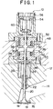
- Fig. 1 is a sectional view of an electromagnetically driven valve 10 according to a first embodiment of the present invention.
- the electromagnetically driven valve 10 is employed as an exhaust valve for an internal combustion engine.
- the electromagnetically driven valve 10 is attached to a cylinder head 12 in which an exhaust port 14 is formed.
- Formed in a lower portion of the cylinder head 12 is a combustion chamber 16.
- the electromagnetically driven valve 10 is provided with a valve body 18 for bringing the exhaust port 14 into or out of communication with the combustion chamber 16.
- a valve seat 19 onto which the valve body moves is disposed in the exhaust port 14.
- the exhaust port 14 is brought into communication with the combustion chamber 16 when the valve body 18 moves away from the valve seat 19, while the exhaust port 14 is brought out of communication with the combustion chamber 16 when the valve body 18 moves onto the valve seat 19.
- a valve shaft 20 is formed integrally with the valve body 18.
- a valve guide 22 is disposed inside the cylinder head 12.
- the valve shaft 20 is slidably held by the valve guide 22.
- a lower retainer 24 is attached to an upper end portion of the valve shaft 20.
- a lower spring 26 is disposed beneath the lower retainer 24. The lower spring 26 urges the lower retainer 24 upwards in Fig. 1.
- valve shaft 20 abuts against an armature shaft 28 made of a non-magnetic material.
- Upper core 32 and a lower core 34 are disposed above and below the armature 30 respectively.
- the lower core 34 has an annular protrusion 36, which has a predetermined length and protrudes from a surface of the lower core 34 toward the upper core 32.
- the electromagnetically driven valve 10 according to this embodiment is characterized in that the annular protrusion 36 is formed not on the upper core 32 but only on the lower core 34.
- the annular protrusion 36 has a diameter slightly larger than an outer diameter of the armature 30.
- an inner wall of the annular protrusion 36 faces an outer peripheral surface of the armature 30.
- the outer peripheral surface of the armature 30, which faces the inner peripheral surface of the annular protrusion 36, will hereinafter be referred to as a protrusion facing side 38.
- the upper core 32 and the lower core 34 accommodate an upper coil 40 and a lower coil 42 respectively.
- Bearings 44, 46 are disposed in the vicinity of central axes of the upper core 32 and the lower core 34 respectively.
- the armature shaft 28 is slidably held by the bearings 44, 46.
- a core guide 48 surrounds outer peripheral surfaces of the upper core 32 and the lower core 34.
- the core guide 48 suitably adjusts a location of the upper core 32 relative to the lower core 34.
- An upper case 50 is attached to an upper portion of the upper core 32, while a lower case 52 is attached to a lower portion of the lower core 34.
- a spring guide 54 and an adjuster bolt 56 are disposed in an upper end portion of the upper case 50.
- An upper retainer 58 connected with an upper end of the armature shaft 28 is disposed below the spring guide 54.
- Disposed between the spring guide 54 and the upper retainer 58 is an upper spring 60 which urges the upper retainer 58 and the armature shaft 28 downwards in Fig. 1.
- the adjuster bolt 56 adjusts a neutral position of the armature 30. In this embodiment, the neutral position of the armature 30 is adjusted to a central portion of a space defined by the upper core 32 and the lower core 34.
- the electromagnetically driven valve 10 when no exciting current is supplied to the upper coil 40 or the lower coil 42, the armature 30 assumes its neutral position. That is, the armature 30 is held in a central portion of the space defined by the upper core 32 and the lower core 34.
- an exciting current is supplied to the upper coil 40 with the armature 30 assuming its neutral position, an electromagnetic force attracting the armature 30 toward the upper core 32 is generated in a space defined by the armature 30 and the upper core 32.
- the electromagnetically driven valve 10 can displace the armature 30 toward the upper core 32 by supplying a suitable exciting current to the upper coil 40.
- the valve body 18 moves onto the valve seat 19 to be completely closed prior to abutment of the armature 30 on the upper core 32.
- the electromagnetically driven valve 10 can completely close the valve body 18 by supplying a suitable exciting current to the upper coil 40.
- valve body 18 If supply of an exciting current to the upper coil 40 is stopped with the valve body 18 completely closed, the valve body 18, the valve shaft 20, the armature shaft 28 and the armature 30 start to move downwards in Fig. 1 due to urging forces of the upper spring 60 and the lower spring 26.
- Displacement of the valve body 18 causes energy loss resulting from sliding friction and the like.
- the electromagnetically driven valve 10 can compensate for such energy loss by supplying an exciting current to the lower coil 42 to displace the valve body 18 until the armature 30 abuts against the lower core 34.
- the valve body 18 becomes completely open when the armature 30 abuts against the lower core 34.
- the electromagnetically driven valve 10 can completely open the valve body 18 by starting to supply an exciting current to the lower coil 42 at a suitable time after stoppage of the supply of the exciting current to the upper coil 40.
- the electromagnetically driven valve 10 can suitably open or close the valve body 18 by supplying at a suitable time thereafter a suitable exciting current to the upper coil 40 or the lower coil 42.
- the electromagnetically driven valve 10 is characterized in that the annular protrusion 36 is formed not on the upper core 32 but only on the lower core 34. The effect achieved by this feature will be described hereinafter.
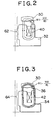
- Fig. 2 illustrates flow of a magnetic flux U circulating through the upper core 32 and the armature 30 when a predetermined current I 0 is supplied to the upper coil 40.
- the flow of the magnetic flux U as illustrated in Fig. 2 is realized when the armature 30 is spaced far apart from the upper core 32.
- N represents the number of turns of the upper coil 40
- R U represents a reluctance of a magnetic circuit including the upper core 32 and the armature 30 (hereinafter referred to as an upper magnetic circuit 62)
- the magnetic flux U circulating through the upper magnetic circuit 62 is expressed as follows.
- U (NI 0 )/R U
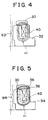
- Fig. 3 illustrates flow of a magnetic flux L circulating through the lower core 34 and the armature 30 when a predetermined current I 0 is supplied to the lower coil 42.
- the flow of the magnetic flux L as illustrated in Fig. 3 is realized when the armature 30 is spaced far apart from the lower core 34.
- N represents the number of turns of the lower coil 42
- R L represents a reluctance of a magnetic circuit including the lower core 34 and the armature 30 (hereinafter referred to as a lower magnetic circuit 64)
- the magnetic flux L circulating through the lower magnetic circuit 64 is expressed as follows.
- L (N I 0 )/R L
- the annular protrusion 36 protruding toward the armature 30 is formed on the lower core 34.
- the annular protrusion 36 serves to reduce the air gap formed therebetween.
- the reluctance R L of the lower magnetic circuit 64 is smaller than the reluctance R U of the upper magnetic circuit 62. Accordingly, in this case, the amount of magnetic flux L flowing through the lower magnetic circuit 64 is larger than the amount of magnetic flux U flowing through the upper magnetic circuit 62.
- the aforementioned attracting force mainly serves to attract the armature 30 toward the upper core 32. If the armature 30 is spaced far apart from the lower core 34, the aforementioned attracting force mainly serves to attract the armature 30 toward the lower core 34. The larger the amount of magnetic flux flowing through the air gap to be reduced becomes, the larger the aforementioned attracting force becomes.
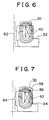
- Fig. 4 illustrates flow of a magnetic flux U circulating through the upper core 32 and the armature 30 when a predetermined current I 0 is supplied to the upper coil 40.
- the flow of the magnetic flux U as illustrated in Fig. 4 is realized when the armature 30 is spaced slightly apart from the upper core 32.
- the reluctance R U of the upper magnetic circuit 62 becomes.
- the reluctance R U becomes, the larger the amount of magnetic flux U flowing through the upper magnetic circuit 62 becomes.
- the amount of magnetic flux U flowing through the upper magnetic circuit 62 is larger when the armature 30 is close to the upper core 32 as illustrated in Fig. 4 than when the armature 30 is spaced far apart from the upper core 32 as illustrated in Fig. 2.
- the magnetic flux U which is transferred between the armature 30 and the upper core 32, mainly serves as an attracting force that attracts the armature 30 toward the upper core 32 even when the armature 30 is spaced slightly apart from the upper core 32.
- the attracting force that attracts the armature 30 toward the upper core 32 increases in proportion with the magnetic flux U flowing through the upper magnetic circuit 62.
- an attracting force that attracts the armature 30 toward the upper core 32 will hereinafter be referred to as a close-state attracting force F N .
- Fig. 5 illustrates flow of a magnetic flux L circulating through the lower core 34 and the armature 30 when a predetermined current I 0 is supplied to the lower coil 42.
- the flow of the magnetic flux L as illustrated in Fig. 5 is realized when the armature 30 is spaced slightly apart from the lower core 34.
- a magnetic flux is transferred between the armature 30 and the lower core 34 via an air gap formed between the protrusion facing side 38 of the armature 30 and the annular protrusion 36 of the lower core 34 (hereinafter referred to as a radial air gap) as well as an air gap formed between a bottom face of the armature 30 and an upper face of the lower core 34 (hereinafter referred to as an axial air gap).
- the magnetic flux transferred via the axial air gap serves as an attracting force that always attracts the armature 30 toward the lower core 34.
- the magnetic flux transferred via the radial air gap acts on the armature 30 in the radial direction such that the armature 30 is not urged toward the lower core 34. Therefore, when the armature 30 is close to the lower core 34, the larger the magnetic flux flowing through the axial air gap becomes, the larger the attracting force (the close-state attracting force F N ) that attracts the armature 30 toward the lower core 34 becomes.
- the axial air gap decreases in proportion with a displacement amount of the armature 30 and reaches its minimum value of "0" upon abutment of the armature 30 on the lower core 34.
- the radial air gap reaches its minimum value G MIN upon arrival of a lower end portion of the protrusion facing side 38 on an upper end portion of the annular protrusion 36. Accordingly, the radial air gap is smaller than the axial air gap until the axial air gap becomes smaller than G MIN after arrival of the lower end portion of the protrusion facing side 38 on the upper end portion of the annular protrusion 36.
- the magnetic flux L flowing through the lower magnetic circuit 64 tends to follow a route having a small reluctance.
- the close-state attracting force F N assumes a relatively small value for the magnetic flux L .
- the close-state attracting force F N undergoes relatively gradual changes.
- the electromagnetically driven valve 10 ensures that the close-state attracting force F N generated between the armature 30 and the lower core 34 (hereinafter referred to as a lower close-state attracting force) is smaller than the close-state attracting force F N generated between the armature 30 and the upper core 32 (hereinafter referred to as an upper close-state attracting force).
- the lower close-state attracting force generated as the armature 30 approaches the lower core 34 changes more gradually than the upper close-state attracting force generated as the armature 30 approaches the upper core 32.
- Fig. 6 illustrates flow of a magnetic flux U circulating through the upper core 32 and the armature 30 when a predetermined current I 0 is supplied to the upper coil 40.
- the flow of the magnetic flux U as illustrated in Fig. 6 is realized when the armature 30 abuts against the upper core 32.
- the reluctance R U of the upper magnetic circuit 62 assumes its minimum value when the armature 30 abuts against the upper core 32. In this case, given an exciting current I 0 , the maximum magnetic flux UMAX flows through the upper magnetic circuit 62 and the maximum attracting force is generated between the armature 30 and the upper core 32. This attracting force will hereinafter be referred to as an abutment-state attracting force F C .
- Fig. 7 illustrates flow of a magnetic flux L circulating through the lower core 34 and the armature 30 when a predetermined current I 0 is supplied to the lower coil 42.
- the flow of the magnetic flux L as illustrated in Fig. 7 is realized when the armature 30 abuts against the lower core 34.
- the reluctance R L of the lower magnetic circuit 64 assumes its minimum value when the armature 30 abuts against the lower core 34. In this case, given an exciting current I 0 , the maximum magnetic flux LMAX flows through the lower magnetic circuit 64. In this embodiment, the air gap formed between the protrusion facing side 38 of the armature 30 and the annular protrusion 36 of the lower core 34 always exceeds the minimum value G MIN . Thus, when the armature 30 abuts against the lower core 34, almost all of the magnetic flux L is transferred between the bottom face of the armature 30 and the upper face of the lower core 34.
- an abutment-state attracting force F C is generated between the armature 30 and the lower core 34.
- This abutment-state attracting force F C is substantially equal to the abutment-state attracting force F C generated between the armature 30 and the upper core 32.
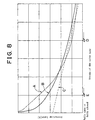
- Fig. 8 illustrates characteristics of the electromagnetically driven valve 10 in accordance with changes in stroke of the valve body 18.
- a curve A indicates an attracting force generated between the armature 30 and the upper core 32 when the valve body 18 is displaced between its neutral position and its fully closed position with an exciting current I 0 supplied to the upper coil 40.
- a curve B indicates an attracting force generated between the armature 30 and the lower core 34 when the valve body 18 is displaced between its neutral position and its fully open position with the exciting current I 0 supplied to the lower coil 42.
- a curve C indicates a spring force generated by the upper spring 60 and the lower spring 26 when the valve body 18 is displaced between its neutral position and its fully open position or between its neutral position and its fully closed position.
- an exciting current I 0 is supplied to both the upper coil 40 and the lower coil 42, the spaced-state attracting force F F is larger between the armature 30 and the lower core 34 than between the armature 30 and the upper core 32.
- the close-state attracting force F N is smaller between the armature 30 and the lower core 34 than between the armature 30 and the upper core 32.
- the abutment-state attracting force F C generated between the armature 30 and the upper core 32 is substantially equal to the abutment-state attracting force F C generated between the armature 30 and the lower core 34.
- the attracting force generated between the armature 30 and the upper core 32 is relatively small when the valve body 18 is located in the vicinity of its neutral position. This attracting force tends to increase relatively steeply as the valve body 18 approaches its fully closed position.
- the curve B indicates, the attracting force generated between the armature 30 and the lower core 34 is relatively large when the valve body 18 is located in the vicinity of its neutral position. This attracting force tends to increase relatively gradually as the valve body 18 approaches its fully open position.
- the electromagnetically driven valve 10 is used as an exhaust valve for an internal combustion engine.
- the electromagnetically driven valve 10 operates to open the valve body 18 when a high combustion pressure remains in the combustion chamber 16 and close the valve body 18 after release of the combustion pressure. If the valve body 18 is displaced toward its fully open position when a high combustion pressure remains in the combustion chamber 16, a large load is applied to the valve body 18. On the other hand, when the valve body 18 is thereafter displaced toward its fully closed position, such a large load is not applied to the valve body.
- the electromagnetically driven valve 10 is constructed such that the valve body 18, when in its fully closed position after stoppage of supply of an exciting current to the upper coil 40, is displaced toward its fully open position by urging forces of the upper spring 60 and the lower spring 26.
- the electromagnetically driven valve 10 is constructed such that the valve body 18, when in its fully open position after stoppage of supply of an exciting current to the lower coil, is displaced toward its fully closed position by urging forces of the upper spring 60 and the lower spring 26.
- a critical position that can be reached by the valve body 18 due to urging forces of the upper spring 60 and the lower spring 26 during the valve opening operation of the valve body 18 is marked as D.
- a critical position that can be reached by the valve body 18 due to urging forces of the upper spring 60 and the lower spring 26 during the valve closing operation of the valve body 18 is marked as E.
- the valve body 18 is subjected to a larger load during the valve opening operation than during the valve closing operation.
- the critical position D is closer to the neutral position of the valve body 18 than is the critical position E.
- the electromagnetically driven valve 10 In order to suitably displace the valve body 18 to its fully open position, when the valve body 18 is located at the critical position D, it is necessary to generate an attracting force that exceeds spring forces generated by the upper spring 60 and the lower spring 26 (the spring forces that urge the valve body 18 toward its neutral position). As the curve B and the straight line C in Fig. 8 indicate, the electromagnetically driven valve 10 satisfies the aforementioned requirement. Hence, the electromagnetically driven valve 10 can suitably displace the valve body 18 to its fully open position.
- the valve body 18 When the valve body 18 is displaced toward the upper core 32 by a distance corresponding to the critical position D, the attracting force generated between the armature 30 and the upper core 32 is smaller than the spring forces generated by the upper spring 60 and the lower spring 26.
- the lower core 34 is constructed in the same manner as the upper core 32, that is, unless the lower core 34 is provided with the annular protrusion 36, the valve body 18 cannot be displaced suitably to its fully closed position by supplying an exciting current I 0 to the lower coil 42.
- the electromagnetically driven valve 10 is constructed such that the valve body 18 can be displaced to its fully closed position with a low electric power consumption.
- the electromagnetically driven valve 10 In order to suitably displace the valve body 18 to its fully closed position, when the valve body 18 is located at the critical position E, it is necessary to generate an attracting force that exceeds spring forces generated by the upper spring 60 and the lower spring 26 (the spring forces that urge the valve body 18 toward its neutral position). As the curve A and the straight line C in Fig. 8 indicate, the electromagnetically driven valve 10 satisfies the aforementioned requirement. Hence, the electromagnetically driven valve 10 can suitably displace the valve body 18 to its fully closed position.
- the upper core 32 is more suitable in structure than the lower core 34 to generate a close-state attracting force F N sufficiently large from the exciting current I 0 .
- the upper core 32 is more suitable in structure than the lower core 34 to generate an attracting force exceeding the spring forces generated by the upper spring 60 and the lower spring 26 with a low electric power consumption when the valve body 18 is located at the critical position E.
- the exciting current supplied to the upper coil 40 is set to such a value that the attracting force generated between the armature 30 and the upper core 32 when the valve body 18 is located at the critical position E slightly exceeds the spring forces generated by the upper spring 60 and the lower spring 26.
- valve body 18 While the internal combustion engine is in operation, the valve body 18 needs to be held either at its fully closed position or at its fully open position.
- the electromagnetically driven valve 10 can hold the valve body 18 at either its fully closed position or its fully open position by supplying a suitable exciting current to the lower coil 42 or the upper coil 40 after arrival of the valve body 18 at its fully open or closed position - that is, after arrival of the armature 30 on the lower core 34 or the upper core 32.
- the electromagnetically driven valve 10 makes it possible to drastically economize on electric power not only in displacing the valve body 18 to its fully closed position but also in displacing the valve body 18 to its fully open position.
- the characteristics of the electromagnetically driven valve 10 according to this embodiment are determined in view of the relationship between timings for opening and closing the valve body 18 and operating conditions of the internal combustion engine.
- the electromagnetically driven valve 10 can suitably open and close the valve body 18, while making it possible to drastically economize on electric power.
- the upper core 32 is not provided with a protrusion in this embodiment, the present invention is not limited to such a construction.
- the upper core 32 may be provided with a protrusion that is smaller than the annular protrusion 36.
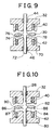
- Fig. 9 is a sectional view illustrating a part surrounding the armature of the electromagnetically driven valve according to the second embodiment.
- like elements are denoted by like reference numerals. Referring to Fig. 9, the description of those elements constructed in the same manner as in Fig. 1 will be omitted.
- the electromagnetically driven valve according to this embodiment is realized by substituting a lower core 70 and an armature shaft 72 as illustrated in Fig. 9 for the lower core 34 and the armature shaft 28 as illustrated in Fig. 1.
- the lower core 70 has an annular protrusion 74 surrounding the armature shaft 72.
- the armature shaft 72 has a recess 76 accommodating the annular protrusion 74.
- the armature shaft 72 is connected with the armature 30 at the recess 76.
- a protrusion facing side 78 is formed on an inner peripheral surface of the armature 30.
- the protrusion facing side 78 of the armature 30 faces an outer peripheral surface of the annular protrusion 74. Since the inner diameter of the armature 30 is slightly larger than the outer diameter of the annular protrusion 74, a predetermined clearance is always formed between the protrusion facing side 78 and the annular protrusion 74.
- the annular protrusion 74 and the protrusion facing side 78 operate substantially in the same manner as the annular protrusion 36 and the protrusion facing side 38.
- the electromagnetically driven valve according to this embodiment can suitably open and close the valve body 18, while making it possible to drastically economize on electric power.
- Fig. 10 is a sectional view illustrating a part surrounding the armature of the electromagnetically driven valve according to the third embodiment.
- like elements are denoted by like reference numerals. Referring to Fig. 10, the description of those elements constructed in the same manner as in Fig. 1 will be omitted.
- the electromagnetically driven valve according to this embodiment is realized by substituting a lower core 80 and an armature 82 as illustrated in Fig. 10 for the lower core 34 and the armature 30 as illustrated in Fig. 1.
- the lower core 80 has a first annular protrusion 84 and an annular groove 86.
- the first annular protrusion 84 is disposed along the outermost periphery of the lower core 80 and the annular groove 86 is located radially inward of the first annular protrusion 84.
- a first protrusion facing side 87 is formed on an inner peripheral surface of the first annular protrusion 84.
- a second annular protrusion 88 is disposed along the outermost periphery of the armature 82.
- a second protrusion facing side 90 is formed on an outer peripheral surface of the second annular protrusion 88.
- the second annular protrusion 88 is disposed so as to be fitted with the annular groove 86 of the lower core 80 when the armature 82 is close to the lower core 80.
- the second protrusion facing side 90 faces an inner wall of the first annular protrusion 84. That is, the outer peripheral surface of the second annular protrusion 88 faces the first protrusion facing side 87. Since the outer diameter of the armature 82 is slightly smaller than the outer diameter of the first annular protrusion 84, a predetermined clearance is always formed between the first annular protrusion 84 and the second protrusion facing side 90.
- the first annular protrusion 84 and the second annular protrusion 88 operate substantially in the same manner as the annular protrusion 36 in the first embodiment. Further, the first protrusion facing side 87 and the second protrusion facing side 90 operate substantially in the same manner as the protrusion facing side 38 in the first embodiment.
- the electromagnetically driven valve according to this embodiment can suitably open and close the valve body 18, while making it possible to drastically economize on electric power.
- the armature 82 is not provided with a protrusion protruding therefrom toward the upper core 32 in this embodiment, the present invention is not limited to such a construction.
- a protrusion smaller than the second annular protrusion 88 may be formed on the side of the armature 82 that faces the upper core 32.
- the present invention is not limited to such a construction. It may also be possible to provide only the armature 82 with an annular protrusion.
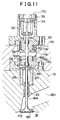
- Fig. 11 is an overall structural view of an electromagnetically driven valve 170 according to the fourth embodiment.
- the electromagnetically driven valve 170 is characterized in that it is provided with an intake valve 172 and an annular protrusion 176 is formed only on an upper core 174.
- like elements are denoted by like reference numerals. Referring to Fig. 11, the description of those elements constructed in the same manner as in Fig. 1 will be omitted or simplified.
- Formed in the cylinder head 12 is an intake port 180 in which a valve seat 182 is disposed. When the intake valve 172 moves onto the valve seat 182, the intake port 180 is brought out of communication with the combustion chamber 16. When the intake valve 172 moves away from the valve seat 182, the intake port 180 is brought into communication with the combustion chamber 16.
- the intake valve 172 is opened when no combustion pressure remains in the combustion chamber 16. Thus, whether the intake valve 172 is driven to be opened or closed, there is no substantial change in an external force impeding the operation of the intake valve 172. As a result, the amount of amplitude damped by the external force remains substantially unchanged regardless of whether the intake valve 172 is driven to be opened or closed.
- the electromagnetically driven valve 170 is constructed such that the intake valve 172 reliably moves onto the valve seat 182 without being adversely affected by thermal expansion of a valve shaft 184 and the like. That is, the electromagnetically driven valve 170 is constructed such that even if the valve shaft 184 and the like thermally expand, the intake valve 172 always reaches the valve seat 182 prior to arrival of the armature 30 on the upper core 174. Therefore, as the armature 30 is attracted toward the upper coil 40, the electromagnetically driven valve 170 may bring about circumstances where only the armature 30 and the armature shaft 28 are separated from the valve shaft 184 and move toward the upper coil 40 after arrival of the intake valve 172 on the valve seat 182.
- the electromagnetically driven valve 170 brings about circumstances where the armature shaft 28 is separated from the valve shaft 184 after close approximation of the armature 30 to the upper coil 40. Under such circumstances, the spring force of the lower spring 26 is not transmitted to the armature shaft 28, to which only the spring force of the upper spring 60 is transmitted.
- the upper spring 60 generates a spring force urging the armature 30 toward the lower coil 42. Hence, when only the spring force generated by the upper spring 60 acts on the armature shaft 28, the amplitude of the armature 30 moving toward the upper coil 40 is abruptly damped.
- both the spring force of the upper spring 60 and the spring force of the lower spring 26 constantly act on the armature shaft 28 until the armature 30 reaches the lower coil 42 after separation of the armature 30 from the upper coil 40.
- the amplitude of the armature 30 is not abruptly damped.
- the electromagnetically driven valve 170 ensures that the spring forces of the upper spring 60 and the lower spring 26 damp the amplitude of the armature shaft 28 more drastically when the armature 30 moves toward the upper coil 40 than when the armature 30 moves toward the lower coil 42.
- the amplitude of the intake valve 172 tends to be damped more drastically during the valve closing operation than during the valve opening operation.
- the upper core 174 is provided with the annular protrusion 176 surrounding the armature 30.
- the attracting force generated between the armature 30 and the upper core 174 is relatively large when the intake valve 172 is located in the vicinity of its neutral position, so that the aforementioned difference in damping amount of amplitude can be eliminated. Accordingly, while the internal combustion engine is in operation, the electromagnetically driven valve 170 can suitably open and close the valve body, while making it possible to drastically economize on electric power.
Landscapes
- Engineering & Computer Science (AREA)
- General Engineering & Computer Science (AREA)
- Physics & Mathematics (AREA)
- Electromagnetism (AREA)
- Mechanical Engineering (AREA)
- Power Engineering (AREA)
- Valve Device For Special Equipments (AREA)
- Magnetically Actuated Valves (AREA)
Description
Claims (4)
- An electromagnetically driven valve for an internal combustion engine havingcharacterized in thatan armature (30), coupled to a valve body (18) for reciprocal movement therewith between a first position and a second position;a first elastic member (26), coupled to said armature (30) to bias said armature (30) toward the second position, anda second elastic member (60), coupled to said armature (30) to bias said armature (30) toward the first position,wherein a neutral position of said armature (30) is defined between the first and second positions at the point where the forces applied from said first and second elastic members (26, 60) balance one another,a first core (34) including a first coil (42) therein anda second core (32) including a second coil (40) therein,wherein said first and second cores (34, 32) are disposed on opposite sides of said armature (30) and are positioned so that, when said armature (30) is in the neutral position, said first and second cores (34, 32) are spaced apart from said armature (30), andwherein said valve body (18) is an exhaust valve for an internal combustion engine and said first coil (42) generates an electromagnetic force to attract said armature (30) toward the first position in which said exhaust valve is open,
said first core (34) is provided with a first protrusion (36) protruding a predetermined length toward said armature (30), thereby making a distance between said first core (34) and said armature (30) smaller than a distance between said second core (32) and said armature (30) when said armature (30) is located in the neutral position, said first protrusion (36) being annular and having a diameter slightly larger than an outer diameter of said armature (30). - An electromagnetically driven valve for an internal combustion engine havingcharacterized in thatan armature (30), coupled to a valve body (172) for reciprocal movement therewith between a first position and a second position;a first elastic member (26), coupled to said armature (30) to bias said armature (30) toward the second position, anda second elastic member (60) coupled to said armature (30) to bias said armature (30) toward the first position,wherein a neutral position of said armature (30) is defined between the first and second positions at the point where the forces applied from said first and second elastic members (26, 60) balance one another,a first core (188) including a first coil (42) therein anda second core (174) including a second coil (40) therein,wherein said first and second cores (188, 174) are disposed on opposite sides of said armature (30) and are positioned so that, when said armature (30) is in the neutral position, said first and second cores (188, 174) are spaced apart from said armature (30), andwherein said valve body (172) is an intake valve for an internal combustion engine and is separated from said armature (30), and said second coil (40) generates an electromagnetic force attracting the armature (30) toward the second position to close said intake valve,
said second core (174) is provided with a first protrusion (176) protruding a predetermined length toward said armature (30), thereby making a distance between said second core (174) and said armature (30) smaller than a distance between said first core (188) and said armature (30) when said armature (30) is located in the neutral position, said first protrusion (176) being annular and having a diameter slightly larger than an outer diameter of said armature (30). - The electromagnetically driven valve according to claim 1, characterized in that said second core (32) is provided with a second protrusion that is smaller than said first protrusion (36).
- The electromagnetically driven valve according to claim 2, characterized in that said first core (188) is provided with a second protrusion that is smaller than said first protrusion (176).
Priority Applications (1)
| Application Number | Priority Date | Filing Date | Title |
|---|---|---|---|
| EP02018382A EP1258602B1 (en) | 1997-09-22 | 1998-07-17 | Electromagnetically driven valve for an internal combustion engine |
Applications Claiming Priority (6)
| Application Number | Priority Date | Filing Date | Title |
|---|---|---|---|
| JP25705097 | 1997-09-22 | ||
| JP25705097A JP3458671B2 (en) | 1997-09-22 | 1997-09-22 | Solenoid driven valve |
| JP257050/97 | 1997-09-22 | ||
| JP305912/97 | 1997-11-07 | ||
| JP30591297 | 1997-11-07 | ||
| JP30591297A JP3596256B2 (en) | 1997-11-07 | 1997-11-07 | Electromagnetic drive valve for internal combustion engine |
Related Child Applications (1)
| Application Number | Title | Priority Date | Filing Date |
|---|---|---|---|
| EP02018382.8 Division-Into | 2002-08-14 |
Publications (3)
| Publication Number | Publication Date |
|---|---|
| EP0903472A2 EP0903472A2 (en) | 1999-03-24 |
| EP0903472A3 EP0903472A3 (en) | 1999-05-12 |
| EP0903472B1 true EP0903472B1 (en) | 2003-09-17 |
Family
ID=26543031
Family Applications (2)
| Application Number | Title | Priority Date | Filing Date |
|---|---|---|---|
| EP02018382A Revoked EP1258602B1 (en) | 1997-09-22 | 1998-07-17 | Electromagnetically driven valve for an internal combustion engine |
| EP98113408A Revoked EP0903472B1 (en) | 1997-09-22 | 1998-07-17 | Electromagnetically driven valve for an internal combustion engine |
Family Applications Before (1)
| Application Number | Title | Priority Date | Filing Date |
|---|---|---|---|
| EP02018382A Revoked EP1258602B1 (en) | 1997-09-22 | 1998-07-17 | Electromagnetically driven valve for an internal combustion engine |
Country Status (4)
| Country | Link |
|---|---|
| US (2) | US6125803A (en) |
| EP (2) | EP1258602B1 (en) |
| KR (1) | KR100301880B1 (en) |
| DE (2) | DE69818184T2 (en) |
Families Citing this family (23)
| Publication number | Priority date | Publication date | Assignee | Title |
|---|---|---|---|---|
| JP4047468B2 (en) * | 1998-11-26 | 2008-02-13 | 本田技研工業株式会社 | Electromagnetically driven valve for internal combustion engine |
| JP2001178105A (en) * | 1999-12-22 | 2001-06-29 | Honda Motor Co Ltd | Electromagnet actuator |
| WO2001063626A2 (en) * | 2000-02-22 | 2001-08-30 | Bergstrom Gary E | An improved system to determine solenoid position and flux without drift |
| US6308667B1 (en) * | 2000-04-27 | 2001-10-30 | Visteon Global Technologies, Inc. | Actuator for engine valve with tooth and socket armature and core for providing position output and/or improved force profile |
| JP3707354B2 (en) * | 2000-06-02 | 2005-10-19 | 日産自動車株式会社 | Control device for electromagnetically driven valve |
| JP2003065461A (en) * | 2001-08-24 | 2003-03-05 | Toyota Motor Corp | Control device for electromagnetically driven valve |
| US7053742B2 (en) * | 2001-12-28 | 2006-05-30 | Abb Technology Ag | Electromagnetic actuator having a high initial force and improved latching |
| US6950000B1 (en) * | 2001-12-28 | 2005-09-27 | Abb Technology Ag | High initial force electromagnetic actuator |
| US6997146B2 (en) * | 2002-05-22 | 2006-02-14 | Toyota Jidosha Kabushiki Kaisha | Start control method and apparatus for solenoid-operated valves of internal combustion engine |
| US20040127855A1 (en) * | 2002-10-10 | 2004-07-01 | Nmt Medical, Inc. | Hemostasis valve |
| DE202004011676U1 (en) * | 2004-07-26 | 2004-12-16 | Trw Automotive Gmbh | Electromagnetic linear adjusting device for operating a gas exchange valve in an internal combustion (IC) engine has a cup core with a support surface |
| US7619861B2 (en) * | 2004-09-29 | 2009-11-17 | Pass & Seymour, Inc. | Protective device having a thin construction |
| DE102005026415A1 (en) * | 2005-06-03 | 2006-12-07 | Siemens Ag | Electromagnetic drive device |
| RU2482370C2 (en) * | 2008-09-09 | 2013-05-20 | Артемис Интеллиджент Пауэр Лимитед | Valve assembly |
| US8556006B1 (en) | 2009-05-21 | 2013-10-15 | Louis E. Navarro | Vehicle magnetic drive apparatus |
| US8056541B1 (en) * | 2010-06-22 | 2011-11-15 | DONICK ENGINES, Inc. | Internal combustion engine having an electric solenoid poppet valve and air/fuel injector |
| JP5537472B2 (en) * | 2011-03-10 | 2014-07-02 | 日立オートモティブシステムズ株式会社 | Fuel injection device |
| JP6421745B2 (en) * | 2015-12-11 | 2018-11-14 | オムロン株式会社 | relay |
| JP6575343B2 (en) | 2015-12-11 | 2019-09-18 | オムロン株式会社 | relay |
| DE102016203083A1 (en) * | 2016-02-26 | 2017-08-31 | Robert Bosch Gmbh | magnetic valve |
| US10726985B2 (en) * | 2018-03-22 | 2020-07-28 | Schaeffler Technologies AG & Co. KG | Multi-stage actuator assembly |
| GB202005894D0 (en) * | 2020-04-22 | 2020-06-03 | Wastling Michael | Fast-acting toggling armature uses centring spring |
| CN119467827A (en) * | 2024-11-19 | 2025-02-18 | 河南航天液压气动技术有限公司 | High linearity proportional valve |
Citations (1)
| Publication number | Priority date | Publication date | Assignee | Title |
|---|---|---|---|---|
| EP0722039A1 (en) * | 1995-01-11 | 1996-07-17 | Toyota Jidosha Kabushiki Kaisha | Valve operating apparatus of internal combustion engine |
Family Cites Families (15)
| Publication number | Priority date | Publication date | Assignee | Title |
|---|---|---|---|---|
| DE3311250C2 (en) * | 1983-03-28 | 1985-08-01 | FEV Forschungsgesellschaft für Energietechnik und Verbrennungsmotoren mbH, 5100 Aachen | Device for the electromagnetic actuation of a gas exchange valve for positive displacement machines |
| DE3513105A1 (en) * | 1985-04-12 | 1986-10-16 | Fleck, Andreas, 2000 Hamburg | ELECTROMAGNETIC ACTUATOR FOR GAS EXCHANGE VALVES |
| DE3513103A1 (en) * | 1985-04-12 | 1986-10-16 | Fleck, Andreas, 2000 Hamburg | ELECTROMAGNETIC WORKING ACTUATOR |
| DE3826975A1 (en) * | 1988-08-09 | 1990-02-15 | Meyer Hans Wilhelm | CONTROL DEVICE FOR A GAS EXCHANGE VALVE |
| DE3920976A1 (en) * | 1989-06-27 | 1991-01-03 | Fev Motorentech Gmbh & Co Kg | ELECTROMAGNETIC OPERATING DEVICE |
| JPH0379528A (en) * | 1989-08-21 | 1991-04-04 | Konica Corp | Paper feeding device |
| JPH07301105A (en) * | 1994-05-06 | 1995-11-14 | Honda Motor Co Ltd | Valve system for internal combustion engine |
| US5636601A (en) * | 1994-06-15 | 1997-06-10 | Honda Giken Kogyo Kabushiki Kaisha | Energization control method, and electromagnetic control system in electromagnetic driving device |
| JPH07335437A (en) * | 1994-06-15 | 1995-12-22 | Honda Motor Co Ltd | Energization control method in electromagnetic drive device |
| DE19608061C2 (en) * | 1996-03-02 | 2000-03-23 | Daimler Chrysler Ag | Electromagnetic valve actuation |
| JP3612906B2 (en) | 1996-03-14 | 2005-01-26 | ソニー株式会社 | Magnetic head |
| JPH09257050A (en) | 1996-03-25 | 1997-09-30 | Matsui Warutaashiyaido Kk | Safety cover for drive wheel |
| JP3605476B2 (en) * | 1996-08-08 | 2004-12-22 | 本田技研工業株式会社 | Valve train for internal combustion engine |
| JP3605478B2 (en) * | 1996-08-21 | 2004-12-22 | 本田技研工業株式会社 | Valve train for internal combustion engine |
| DE29620741U1 (en) * | 1996-11-29 | 1998-03-26 | FEV Motorentechnik GmbH & Co. KG, 52078 Aachen | Narrow-build electromagnetic actuator |
-
1998
- 1998-07-01 US US09/108,507 patent/US6125803A/en not_active Expired - Lifetime
- 1998-07-17 DE DE69818184T patent/DE69818184T2/en not_active Revoked
- 1998-07-17 DE DE69827047T patent/DE69827047T2/en not_active Revoked
- 1998-07-17 EP EP02018382A patent/EP1258602B1/en not_active Revoked
- 1998-07-17 EP EP98113408A patent/EP0903472B1/en not_active Revoked
- 1998-08-31 KR KR1019980035461A patent/KR100301880B1/en not_active Expired - Fee Related
-
2000
- 2000-07-19 US US09/619,648 patent/US6230674B1/en not_active Expired - Lifetime
Patent Citations (1)
| Publication number | Priority date | Publication date | Assignee | Title |
|---|---|---|---|---|
| EP0722039A1 (en) * | 1995-01-11 | 1996-07-17 | Toyota Jidosha Kabushiki Kaisha | Valve operating apparatus of internal combustion engine |
Also Published As
| Publication number | Publication date |
|---|---|
| US6230674B1 (en) | 2001-05-15 |
| EP1258602A2 (en) | 2002-11-20 |
| EP1258602B1 (en) | 2004-10-13 |
| DE69818184T2 (en) | 2004-06-17 |
| DE69818184D1 (en) | 2003-10-23 |
| KR19990029373A (en) | 1999-04-26 |
| EP0903472A3 (en) | 1999-05-12 |
| DE69827047D1 (en) | 2004-11-18 |
| EP1258602A3 (en) | 2002-12-18 |
| US6125803A (en) | 2000-10-03 |
| KR100301880B1 (en) | 2001-11-22 |
| EP0903472A2 (en) | 1999-03-24 |
| DE69827047T2 (en) | 2005-10-20 |
Similar Documents
| Publication | Publication Date | Title |
|---|---|---|
| EP0903472B1 (en) | Electromagnetically driven valve for an internal combustion engine | |
| US6334413B1 (en) | Electromagnetic actuating system | |
| US4779582A (en) | Bistable electromechanical valve actuator | |
| US4455543A (en) | Electromagnetically operating actuator | |
| KR980009861A (en) | Electromagnetic valve | |
| US20040113731A1 (en) | Electromagnetic valve system | |
| US5647311A (en) | Electromechanically actuated valve with multiple lifts and soft landing | |
| US6279524B1 (en) | Electromagnetic actuator having a pneumatic dampening element | |
| US5903070A (en) | Electromagnetic actuator having a slender structure | |
| US6037851A (en) | Electromagnetic actuator | |
| US6830018B2 (en) | Engine valve train | |
| KR20050056880A (en) | Electromagnetic actuator having inherently decelerating actuation between limits | |
| JP4055571B2 (en) | Electromagnetic fuel injection valve | |
| JP2006503228A (en) | Solenoid valve system | |
| JP3458671B2 (en) | Solenoid driven valve | |
| US20050056712A1 (en) | Fuel injection valve | |
| JP3596256B2 (en) | Electromagnetic drive valve for internal combustion engine | |
| US6415751B2 (en) | Gas exchange valve control for internal combustion engines with an electromagnetic actuator, equipped with gas springs | |
| EP1331369B1 (en) | Linear actuator apparatus and actuating control method | |
| EP0995884B1 (en) | Electromagnetic valve driving apparatus provided in an internal combustion engine | |
| JP4147685B2 (en) | Solenoid valve | |
| JPH10141028A (en) | Electromagnetic drive valve mechanism for internal combustion engine | |
| JP2013122967A (en) | Electromagnetic actuator | |
| JP2000008817A (en) | Electromagnetic drive valve | |
| JPH11132018A (en) | Solenoid driven valve |
Legal Events
| Date | Code | Title | Description |
|---|---|---|---|
| PUAI | Public reference made under article 153(3) epc to a published international application that has entered the european phase |
Free format text: ORIGINAL CODE: 0009012 |
|
| 17P | Request for examination filed |
Effective date: 19980814 |
|
| AK | Designated contracting states |
Kind code of ref document: A2 Designated state(s): DE FR GB |
|
| AX | Request for extension of the european patent |
Free format text: AL;LT;LV;MK;RO;SI |
|
| PUAL | Search report despatched |
Free format text: ORIGINAL CODE: 0009013 |
|
| AK | Designated contracting states |
Kind code of ref document: A3 Designated state(s): AT BE CH CY DE DK ES FI FR GB GR IE IT LI LU MC NL PT SE |
|
| AX | Request for extension of the european patent |
Free format text: AL;LT;LV;MK;RO;SI |
|
| AKX | Designation fees paid |
Free format text: DE FR GB |
|
| 17Q | First examination report despatched |
Effective date: 20020207 |
|
| GRAH | Despatch of communication of intention to grant a patent |
Free format text: ORIGINAL CODE: EPIDOS IGRA |
|
| GRAS | Grant fee paid |
Free format text: ORIGINAL CODE: EPIDOSNIGR3 |
|
| GRAA | (expected) grant |
Free format text: ORIGINAL CODE: 0009210 |
|
| AK | Designated contracting states |
Kind code of ref document: B1 Designated state(s): DE FR GB |
|
| REG | Reference to a national code |
Ref country code: GB Ref legal event code: FG4D |
|
| REF | Corresponds to: |
Ref document number: 69818184 Country of ref document: DE Date of ref document: 20031023 Kind code of ref document: P |
|
| ET | Fr: translation filed | ||
| PLBQ | Unpublished change to opponent data |
Free format text: ORIGINAL CODE: EPIDOS OPPO |
|
| PLBI | Opposition filed |
Free format text: ORIGINAL CODE: 0009260 |
|
| PLAX | Notice of opposition and request to file observation + time limit sent |
Free format text: ORIGINAL CODE: EPIDOSNOBS2 |
|
| 26 | Opposition filed |
Opponent name: FEV MOTORENTECHNIK GMBH Effective date: 20040617 |
|
| PLAB | Opposition data, opponent's data or that of the opponent's representative modified |
Free format text: ORIGINAL CODE: 0009299OPPO |
|
| PLBQ | Unpublished change to opponent data |
Free format text: ORIGINAL CODE: EPIDOS OPPO |
|
| PLBB | Reply of patent proprietor to notice(s) of opposition received |
Free format text: ORIGINAL CODE: EPIDOSNOBS3 |
|
| R26 | Opposition filed (corrected) |
Opponent name: FEV MOTORENTECHNIK GMBH Effective date: 20040617 |
|
| APAH | Appeal reference modified |
Free format text: ORIGINAL CODE: EPIDOSCREFNO |
|
| APBP | Date of receipt of notice of appeal recorded |
Free format text: ORIGINAL CODE: EPIDOSNNOA2O |
|
| APBP | Date of receipt of notice of appeal recorded |
Free format text: ORIGINAL CODE: EPIDOSNNOA2O |
|
| APBQ | Date of receipt of statement of grounds of appeal recorded |
Free format text: ORIGINAL CODE: EPIDOSNNOA3O |
|
| APBQ | Date of receipt of statement of grounds of appeal recorded |
Free format text: ORIGINAL CODE: EPIDOSNNOA3O |
|
| REG | Reference to a national code |
Ref country code: GB Ref legal event code: 746 Effective date: 20061025 |
|
| APAH | Appeal reference modified |
Free format text: ORIGINAL CODE: EPIDOSCREFNO |
|
| APBU | Appeal procedure closed |
Free format text: ORIGINAL CODE: EPIDOSNNOA9O |
|
| RDAF | Communication despatched that patent is revoked |
Free format text: ORIGINAL CODE: EPIDOSNREV1 |
|
| RDAG | Patent revoked |
Free format text: ORIGINAL CODE: 0009271 |
|
| STAA | Information on the status of an ep patent application or granted ep patent |
Free format text: STATUS: PATENT REVOKED |
|
| PGFP | Annual fee paid to national office [announced via postgrant information from national office to epo] |
Ref country code: FR Payment date: 20090710 Year of fee payment: 12 |
|
| 27W | Patent revoked |
Effective date: 20090714 |
|
| GBPR | Gb: patent revoked under art. 102 of the ep convention designating the uk as contracting state |
Effective date: 20090714 |
|
| PGFP | Annual fee paid to national office [announced via postgrant information from national office to epo] |
Ref country code: GB Payment date: 20090715 Year of fee payment: 12 Ref country code: DE Payment date: 20090709 Year of fee payment: 12 |