RU2014667C1 - Burner of sodium vapor high-pressure lamp - Google Patents
Burner of sodium vapor high-pressure lamp Download PDFInfo
- Publication number
- RU2014667C1 RU2014667C1 SU5024836A RU2014667C1 RU 2014667 C1 RU2014667 C1 RU 2014667C1 SU 5024836 A SU5024836 A SU 5024836A RU 2014667 C1 RU2014667 C1 RU 2014667C1
- Authority
- RU
- Russia
- Prior art keywords
- sleeve
- tube
- burner
- diameter
- ceramic
- Prior art date
Links
- DGAQECJNVWCQMB-PUAWFVPOSA-M Ilexoside XXIX Chemical compound C[C@@H]1CC[C@@]2(CC[C@@]3(C(=CC[C@H]4[C@]3(CC[C@@H]5[C@@]4(CC[C@@H](C5(C)C)OS(=O)(=O)[O-])C)C)[C@@H]2[C@]1(C)O)C)C(=O)O[C@H]6[C@@H]([C@H]([C@@H]([C@H](O6)CO)O)O)O.[Na+] DGAQECJNVWCQMB-PUAWFVPOSA-M 0.000 title claims abstract description 11
- 229910052708 sodium Inorganic materials 0.000 title claims abstract description 11
- 239000011734 sodium Substances 0.000 title claims abstract description 11
- 239000000919 ceramic Substances 0.000 claims abstract description 14
- 238000004519 manufacturing process Methods 0.000 abstract description 6
- 239000000126 substance Substances 0.000 abstract 1
- 238000005245 sintering Methods 0.000 description 6
- PNEYBMLMFCGWSK-UHFFFAOYSA-N aluminium oxide Inorganic materials [O-2].[O-2].[O-2].[Al+3].[Al+3] PNEYBMLMFCGWSK-UHFFFAOYSA-N 0.000 description 5
- 239000000463 material Substances 0.000 description 5
- 238000010276 construction Methods 0.000 description 2
- 238000000034 method Methods 0.000 description 2
- 239000000843 powder Substances 0.000 description 2
- 239000003870 refractory metal Substances 0.000 description 2
- WFKWXMTUELFFGS-UHFFFAOYSA-N tungsten Chemical group [W] WFKWXMTUELFFGS-UHFFFAOYSA-N 0.000 description 2
- UFHFLCQGNIYNRP-UHFFFAOYSA-N Hydrogen Chemical compound [H][H] UFHFLCQGNIYNRP-UHFFFAOYSA-N 0.000 description 1
- 238000002474 experimental method Methods 0.000 description 1
- 239000007789 gas Substances 0.000 description 1
- 239000001257 hydrogen Substances 0.000 description 1
- 229910052739 hydrogen Inorganic materials 0.000 description 1
- 238000001802 infusion Methods 0.000 description 1
- QSHDDOUJBYECFT-UHFFFAOYSA-N mercury Chemical compound [Hg] QSHDDOUJBYECFT-UHFFFAOYSA-N 0.000 description 1
- 229910052753 mercury Inorganic materials 0.000 description 1
- 238000007789 sealing Methods 0.000 description 1
- 229910000679 solder Inorganic materials 0.000 description 1
- 238000003466 welding Methods 0.000 description 1
Images

Landscapes
- Vessels And Coating Films For Discharge Lamps (AREA)
Abstract
Description
Изобретение относится к электрической промышленности и может быть использовано при производстве газоразрядных ламп, в частности натриевых ламп высокого давления. The invention relates to the electrical industry and can be used in the manufacture of discharge lamps, in particular high pressure sodium lamps.
Известны натриевые лампы высокого давления, в которых используется горелка из поликристаллической окиси алюминия, концы которой герметично запаяны керамическими втулками. Например, в [1] рассматривается конструкция горелки, в которой керамические втулки вставляются в оба конца керамической трубки и герметизируют ее с помощью заварочного материала. High pressure sodium lamps are known in which a polycrystalline alumina burner is used, the ends of which are hermetically sealed with ceramic bushings. For example, in [1], a torch design is considered in which ceramic sleeves are inserted at both ends of a ceramic tube and sealed with a brewing material.
Через отверстия во втулках проходят вводы, подсоединенные к основным электродам, находящимся внутри горелки. Основные электроды содержат спирали из тугоплавкого металла, навитого на вольфрамовый керн. Горелка имеет поддерживающее разряд наполнение, состоящее из паров натрия или натрия и ртути, а также инертного ионизируемого зажигающего газа. Through openings in the bushings pass bushings connected to the main electrodes inside the burner. The main electrodes contain spirals of refractory metal wound on a tungsten core. The burner has a discharge-supporting filling, consisting of sodium or sodium vapor and mercury, as well as an inert ionized ignition gas.
Различные типы керамических втулок используются для герметизации одного или обоих концов трубки из поликристаллической окиси алюминия у такого типа ламп. В [2] использовались втулки с контуром и размером, позволяющим вставлять втулку в отверстие трубки и производить впай без заварочного материала. В такого типа конструкциях втулки изготавливаются из порошка окиси алюминия, имеющего несколько меньшую усадку при спекании, чем порошок трубки. Втулки вставляются в концы трубки и производится первичное спекание, в результате чего втулка запрессовывается. При высокотемпературном спекании втулок и трубок в среде водорода трубка, имеющая большую усадку по сравнению с втулкой, плотно обжимает и спекается в герметичное соединение с втулкой. Various types of ceramic bushings are used to seal one or both ends of a polycrystalline alumina tube for this type of lamp. In [2], bushings with a contour and size were used, which made it possible to insert the sleeve into the tube hole and to weld without brewing material. In this type of construction, the sleeves are made of alumina powder having a slightly lower shrinkage during sintering than the tube powder. The bushings are inserted into the ends of the tube and primary sintering is performed, as a result of which the sleeve is pressed in. In the case of high-temperature sintering of bushings and tubes in a hydrogen medium, a tube having a greater shrinkage as compared with the sleeve tightly compresses and sintered into a sealed connection with the sleeve.
Недостатком указанных конструкций является сложность обеспечения точности геометрических размеров разрядной трубки: втулки трудно располагать с высокой точностью по отношению к заготовке трубки; втулки могут смещаться относительно трубки в процессе сборки, транспортировки в печь, т.е. могут возникать изменения расстояний между втулками, что в конечном итоге не позволяет обеспечить необходимую точность междуэлектродного расстояния горелки. The disadvantage of these designs is the difficulty in ensuring the accuracy of the geometric dimensions of the discharge tube: the bushings are difficult to position with high accuracy with respect to the tube blank; the sleeves can be displaced relative to the tube during assembly, transportation to the furnace, i.e. changes in the distances between the bushings may occur, which ultimately does not allow to provide the necessary accuracy of the interelectrode distance of the burner.
Наиболее близкой по технической сущности к заявляемой конструкции горелки натриевой лампы высокого давления является конструкция горелки, выбранная в качестве прототипа, состоящая из керамической трубки, выполненной из поликристаллической окиси алюминия, по крайней мере на одном из концов которой установлена втулка, цилиндрическая часть которой расположена внутри керамической трубки, а фланцевая часть опирается на торец трубки [3] . Closest to the technical nature of the claimed design of the burner of a high pressure sodium lamp is the design of the burner, selected as a prototype, consisting of a ceramic tube made of polycrystalline alumina, at least one end of which has a sleeve, the cylindrical part of which is located inside the ceramic tube, and the flange portion rests on the end of the tube [3].
Основным недостатком описанной конструкции является то, что при спекании керамической трубки с втулкой, имеющей на фланцевой части большую толщину стенки, чем в зоне соединения с трубкой, происходит неравномерная усадка. При этом отверстие втулки имеет некоторое сужение в области фланца. Такая форма отверстия ухудшает качество герметизации вводов, так как по длине вводов будет разная величина зазоров, причем сужение с наружной части препятствует заполнению места впая заварочным материалов. The main disadvantage of the described construction is that when sintering a ceramic tube with a sleeve having a larger wall thickness on the flange portion than in the zone of connection with the tube, uneven shrinkage occurs. In this case, the bore of the sleeve has some narrowing in the region of the flange. This shape of the hole degrades the quality of sealing of the bushings, since the length of the bushings will have different sizes of gaps, and the narrowing from the outside prevents filling of the solder with infusion materials.
Цель изобретения - увеличение выхода годных горелок в процессе работы производства и повышению надежности работы ламп. The purpose of the invention is to increase the yield of burners during the production process and to increase the reliability of the lamps.
Это достигается тем, что горелка натриевой лампы высокого давления, содержащая керамическую трубку и по крайней мере на одном конце впеченную внутрь керамическую втулку с отверстием, цилиндрическая часть которой расположена внутри трубки, а фланцевая часть опирается на торец трубки, при этом отверстие втулки выполнено ступенчатым, причем отношение его диаметра и глубина со стороны фланца к диаметру на остальной части втулки лежит в пределах 1,15-1,7 и 0,2-0,7 соответственно. This is achieved by the fact that the high-pressure sodium lamp burner contains a ceramic tube and at least one end has a ceramic sleeve embedded inside the tube, the cylindrical part of which is located inside the tube and the flange part rests on the end of the tube, while the hole of the sleeve is stepped, moreover, the ratio of its diameter and depth from the flange to the diameter on the rest of the sleeve lies in the range 1.15-1.7 and 0.2-0.7, respectively.
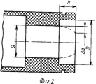
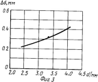
На фиг.1 представлена предлагаемая горелка, общий вид; на фиг.2 - один конец горелки после спекания; на фиг.3 - график зависимости продольного и поперечного сужения отверстия втулки от ее внутреннего диаметра. Figure 1 presents the proposed burner, General view; figure 2 - one end of the burner after sintering; figure 3 is a graph of the longitudinal and transverse narrowing of the bore of the sleeve from its inner diameter.
Горелка натриевой лампы высокого давления (фиг.1) содержит трубку из поликристаллической окиси алюминия с впеченными на концах втулки 1 из такого же материала, что и трубка. Через отверстия во втулках проходят вводы 2, герметично пропаянные с втулками с помощью заварочного материала 3. К вводам 2 приварены вольфрамовые керны 4, на которые навиты основные электроды 5, представляющие собой спираль из тугоплавкого металла. The burner of the high pressure sodium lamp (FIG. 1) comprises a tube of polycrystalline alumina imbedded at the ends of the sleeve 1 of the same material as the tube. Through the holes in the bushings pass
При впекании в трубку втулки с фланцевой частью происходит неравномерная ее усадка в области фланцевой части на величину Δd по внутреннему диаметру и глубине. Неравномерная усадка происходит вследствие того, что в месте соединения трубки с втулкой из-за наличия зазоров между ними суммарная плотность керамической массы трубка-втулка ниже, чем во фланцевой части. В процессе спекания за счет сил поверхностного натяжения происходит частичное перемещение массы втулки в зону меньшей плотности. When a sleeve with a flange part is injected into the tube, it shrinks unevenly in the region of the flange part by an amount Δd in inner diameter and depth. Uneven shrinkage occurs due to the fact that at the junction of the tube with the sleeve due to the presence of gaps between them, the total density of the ceramic mass of the tube-sleeve is lower than in the flange part. In the sintering process, due to surface tension forces, a partial movement of the mass of the sleeve to a zone of lower density occurs.
Устранить указанный недостаток возможно с помощью использования втулки со ступенчатым отверстием в области фланцевой части глубиной h и с диаметром D большим, чем внутренний диаметр d втулки. This drawback can be eliminated by using a sleeve with a stepped hole in the area of the flange part of depth h and with a diameter D larger than the inner diameter d of the sleeve.
Были проведены эксперименты относительно изменения поперечного и продольного сужения отверстия втулки в зависимости от ее внутреннего диаметра. Experiments were conducted regarding changes in the transverse and longitudinal narrowing of the bore of the sleeve depending on its inner diameter.
На фиг. 3 представлен график, иллюстрирующий зависимость поперечного сужения Δd отверстия втулки от величины ее внутреннего диаметра d. Чтобы устранить влияние поперечного сужения на технологичность изготовления горелок, необходимо отверстие втулки выполнить ступенчатым, причем минимальный диаметр D отверстия со стороны фланца должен составить величину не менее d+2 Δd, т.е. отношение D/d диаметра D к диаметру d отверстия должно быть не менее 1,15. In FIG. 3 is a graph illustrating the dependence of the transverse narrowing Δd of the sleeve bore on the magnitude of its inner diameter d. In order to eliminate the influence of the transverse narrowing on the manufacturability of the burners, it is necessary to make the hole of the sleeve stepwise, and the minimum diameter D of the hole on the flange side must be at least d + 2 Δd, i.e. the ratio D / d of the diameter D to the diameter d of the hole should be at least 1.15.
Минимальное значение глубины h определяется значением, при котором поперечное удлинение Δd равно нулю, что наблюдается при h=2 Δd, т.е. отношение h/d равно 0,2. The minimum value of depth h is determined by the value at which the transverse elongation Δd is equal to zero, which is observed at h = 2 Δd, i.e. h / d ratio is 0.2.
Максимальное значение отношения D/d диаметра D к диаметру d втулки равное 1,7, как и максимальное значение отношения h/d глубины h к диаметру d втулки, равное 0,7, выбирались из расчета технологической прочности втулки в процессе ее изготовления и в процессе изготовления горелки. The maximum value of the ratio D / d of diameter D to the diameter d of the sleeve is 1.7, as well as the maximum value of the ratio h / d of depth h to the diameter d of the sleeve equal to 0.7 was chosen from the calculation of the technological strength of the sleeve during its manufacture and in the process burner manufacturing.
В таблице представлены характеристики горелки в соответствии с изобретением. The table shows the characteristics of the burner in accordance with the invention.
Claims (1)
Priority Applications (2)
| Application Number | Priority Date | Filing Date | Title |
|---|---|---|---|
| SU5024836 RU2014667C1 (en) | 1992-01-29 | 1992-01-29 | Burner of sodium vapor high-pressure lamp |
| UA93101260A UA18887A (en) | 1992-01-29 | 1993-02-22 | Burner of high-pressure sodium lamp |
Applications Claiming Priority (1)
| Application Number | Priority Date | Filing Date | Title |
|---|---|---|---|
| SU5024836 RU2014667C1 (en) | 1992-01-29 | 1992-01-29 | Burner of sodium vapor high-pressure lamp |
Publications (1)
| Publication Number | Publication Date |
|---|---|
| RU2014667C1 true RU2014667C1 (en) | 1994-06-15 |
Family
ID=21595664
Family Applications (1)
| Application Number | Title | Priority Date | Filing Date |
|---|---|---|---|
| SU5024836 RU2014667C1 (en) | 1992-01-29 | 1992-01-29 | Burner of sodium vapor high-pressure lamp |
Country Status (2)
| Country | Link |
|---|---|
| RU (1) | RU2014667C1 (en) |
| UA (1) | UA18887A (en) |
-
1992
- 1992-01-29 RU SU5024836 patent/RU2014667C1/en active
-
1993
- 1993-02-22 UA UA93101260A patent/UA18887A/en unknown
Also Published As
| Publication number | Publication date |
|---|---|
| UA18887A (en) | 1997-12-25 |
Similar Documents
| Publication | Publication Date | Title |
|---|---|---|
| EP0528428B1 (en) | High-pressure discharge lamp and method of manufacture | |
| US5404077A (en) | High-pressure discharge lamp | |
| US5352952A (en) | High-pressure discharge lamp with ceramic discharge vessel | |
| US6208070B1 (en) | Metal vapor discharged lamp with specific angle between electrodes and tapered envelope wall | |
| US6194832B1 (en) | Metal halide lamp with aluminum gradated stacked plugs | |
| EP1568066B1 (en) | High-pressure discharge lamp, and method of manufacture thereof | |
| EP2171743B1 (en) | Ignition aid and fitting shroud for discharge lamp | |
| US4765820A (en) | Method of making ceramic arc tube for high-pressure metal-vapor discharge lamp | |
| US4160930A (en) | Electric discharge lamp with annular current conductor | |
| DE4342013A1 (en) | Device for supporting and sealing the lead structure of a lamp | |
| JP2598983Y2 (en) | High pressure discharge lamp | |
| US20020179859A1 (en) | Discharge lamp | |
| US6856091B2 (en) | Seal for ceramic metal halide discharge lamp chamber | |
| US4463281A (en) | High-pressure electric discharge lamp with electrode support | |
| KR870010658A (en) | Surge absorber | |
| RU2014667C1 (en) | Burner of sodium vapor high-pressure lamp | |
| JPH0719575B2 (en) | Arc tube for high-pressure metal vapor discharge lamp and manufacturing method thereof | |
| US5015913A (en) | High-pressure discharge lamp, especially sodium vapor lamp | |
| US4766347A (en) | High-pressure discharge lamp having a lead-through with a protuberance | |
| US6262535B1 (en) | Electrode support tube for high pressure discharge lamp | |
| JPH0794142A (en) | High-pressure discharge lamp | |
| US5391961A (en) | Gas-filled discharge tube | |
| GB2366908A (en) | Metal halide lamp with ceramic discharge vessel | |
| GB2091031A (en) | Discharge vessel for high pressure sodium vapour lamps | |
| JPH11111225A (en) | Closure for discharge lamp |