RU2014503C1 - Rotary compressor - Google Patents
Rotary compressor Download PDFInfo
- Publication number
- RU2014503C1 RU2014503C1 SU4904957A RU2014503C1 RU 2014503 C1 RU2014503 C1 RU 2014503C1 SU 4904957 A SU4904957 A SU 4904957A RU 2014503 C1 RU2014503 C1 RU 2014503C1
- Authority
- RU
- Russia
- Prior art keywords
- chamber
- suction
- discharge
- blades
- windows
- Prior art date
Links
- 239000002131 composite material Substances 0.000 claims description 2
- 230000006835 compression Effects 0.000 abstract description 3
- 238000007906 compression Methods 0.000 abstract description 3
- 230000000694 effects Effects 0.000 abstract description 2
- 239000000126 substance Substances 0.000 abstract 1
- 238000000034 method Methods 0.000 description 2
- 239000010754 BS 2869 Class F Substances 0.000 description 1
- 238000010835 comparative analysis Methods 0.000 description 1
Images
Landscapes
- Applications Or Details Of Rotary Compressors (AREA)
Abstract
Description
Изобретение относится к компрессоростроению и предназначено для сжатия и перемещения газа из области низкого давления в область высокого давления. The invention relates to compressor engineering and is intended for compressing and moving gas from a low-pressure region to a high-pressure region.
Известна конструкция ротационного компрессора, содержащего корпус с цилиндрической рабочей камерой и устройствами газораспределения, камерой синхронизации, концентричные валы, на каждом из которых установлено по одной лопасти, образующих в рабочей камере две торообразные рабочие ячейки переменного объема, и механизм привода валов (Патент США N 2673027, Н.кл. 418-38, 1954). A known design of a rotary compressor containing a housing with a cylindrical working chamber and gas distribution devices, a synchronization chamber, concentric shafts, each of which has one blade, forming two toroidal working cells of variable volume in the working chamber, and a shaft drive mechanism (US Patent No. 2673027 , N.cl. 418-38, 1954).
Недостатком такого компрессора является неуравновешенность лопастей и низкий коэффициент использования объема рабочей камеры, значительную часть которого занимают лопасти. The disadvantage of this compressor is the imbalance of the blades and the low utilization of the volume of the working chamber, a significant part of which is occupied by the blades.
Наиболее близкой является конструкция ротационного компрессора, содержащего корпус с рабочей камерой и камерой синхронизации, камерами всасывания и нагнетания, несколькими окнами всасывания и нагнетания, размещенные в корпусе концентричные валы, на каждом из которых установлены несколько лопастей, образующих в рабочей камере несколько рабочих ячеек переменного объема и механизм привода валов; при этом на лопастях одного из валов закреплен кожух, в котором выполнены газораспределительные отверстия так, что каждое из этих отверстий постоянно сообщается с одной из рабочих ячеек и попеременно сообщается с одним из окон всасывания и с одним из окон нагнетания (Патент США N 4169697, кл. F 01 C 1/42, Н. кл. 418/34, 1979). The closest is the design of a rotary compressor containing a housing with a working chamber and a synchronization chamber, suction and discharge chambers, several suction and discharge windows, concentric shafts located in the housing, each of which has several blades forming several working cells of variable volume in the working chamber and shaft drive mechanism; at the same time, a casing is fixed on the blades of one of the shafts, in which gas distribution openings are made so that each of these openings constantly communicates with one of the working cells and alternately communicates with one of the suction windows and one of the discharge windows (US Patent No. 4169697, cl F 01
В таком компрессоре полностью уравновешены лопасти, закрепленные на валах, и существенно лучше используется объем рабочей камеры при одном и том же максимальном угле раствора рабочих ячеек. Это выгодно отличает конструкцию прототипа от конструкции описанного выше аналога. Однако существенным недостатком такого компрессора является неудачная конструкция газораспределительных отверстий: во-первых, их малое проходное сечение обусловливает повышенные гидравлические потери в процессах всасывания и нагнетания, что снижает экономичность работы компрессора; во-вторых, объем этих отверстий, равный произведению площади их проходного сечения на толщину кожуха, является дополнительным мертвым объемом рабочих ячеек и приводит к снижению производительности компрессора (см., например, Пластинин П.И. Теория и расчет поршневых компрессоров. - М., 1987, с. 42-46). In such a compressor, the blades mounted on the shafts are completely balanced, and the volume of the working chamber is used much better at the same maximum angle of the working cell solution. This compares favorably with the design of the prototype from the design of the analogue described above. However, a significant drawback of such a compressor is the unsuccessful design of the gas distribution openings: firstly, their small flow area causes increased hydraulic losses in the suction and discharge processes, which reduces the efficiency of the compressor; secondly, the volume of these openings, equal to the product of the area of their passage section by the thickness of the casing, is an additional dead volume of working cells and leads to a decrease in compressor productivity (see, for example, Plastinin P.I. Theory and design of reciprocating compressors. - M. , 1987, p. 42-46).
Целью изобретения является повышение экономичности и производительности. The aim of the invention is to increase efficiency and productivity.
Поставленная цель достигается тем, что ротационный компрессор содержит корпус с рабочей камерой, камерами всасывания и нагнетания, камерой синхронизации, окнами всасывания, окнами нагнетания, двумя концентричными валами, на каждом из которых установлены лопасти, размещенные в рабочей камере, и механизм привода валов, размещенный в камере синхронизации, причем на лопастях закреплен газораспределительный кожух, при этом окна всасывания и нагнетания расположены попарно на цилиндрической и на каждой торцевой поверхностях рабочей камеры, а газораспределительный кожух выполнен составным из торцевых и цилиндрических элементов так, что на каждом валу установлены по два торцевых и одному цилиндрическому элементу, причем на каждой лопасти закреплено по два элемента, и каждый элемент закреплен на двух лопастях. This goal is achieved in that the rotary compressor comprises a housing with a working chamber, suction and discharge chambers, a synchronization chamber, suction windows, discharge windows, two concentric shafts, on each of which there are blades placed in the working chamber, and a shaft drive mechanism located in the synchronization chamber, moreover, a gas distribution casing is fixed on the blades, while the suction and discharge windows are arranged in pairs on the cylindrical and on each end surfaces of the working chamber, gas-distributing casing is a composite of the socket and the cylindrical members so that each shaft mounted on two end and one cylindrical member, wherein each blade is fixed on two elements, and each element is fixed to two blades.
В ротационном компрессоре все окна всасывания сообщены с одной камерой всасывания, а все окна нагнетания сообщены с одной камерой нагнетания. In a rotary compressor, all suction windows are in communication with one suction chamber, and all discharge windows are in communication with one discharge chamber.
В ротационном компрессоре два окна всасывания сообщены с одной камерой всасывания, два окна нагнетания сообщены с третьим окном всасывания, а третье окно нагнетания сообщено с камерой нагнетания компрессора. In a rotary compressor, two suction windows are in communication with one suction chamber, two discharge windows are communicated with a third suction window, and a third discharge window is communicated with a compressor discharge chamber.
Сопоставительный анализ с прототипом позволяет сделать вывод, что заявляемое техническое решение содержит ряд конструктивных признаков, связанных с устройством газораспределительного кожуха и размещением окон всасывания и нагнетания в рабочей камере, которых нет в прототипе. Это позволяет сделать вывод о том, что заявляемое техническое решение соответствует критерию "новизна". Comparative analysis with the prototype allows us to conclude that the claimed technical solution contains a number of design features associated with the device of the gas distribution casing and the placement of the suction and discharge windows in the working chamber, which are not in the prototype. This allows us to conclude that the claimed technical solution meets the criterion of "novelty."
Анализ существующей патентной и научно-технической литературы показал, что предлагаемая совокупность заявляемых конструктивных признаков для достижения поставленной цели в настоящее время не известна, что позволяет считать существенными признаки отраженные в формуле изобретения. Analysis of the existing patent and scientific and technical literature showed that the proposed combination of the claimed design features to achieve the goal is not currently known, which allows us to consider the features reflected in the claims to be significant.
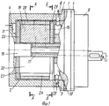
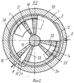
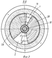
На фиг. 1 схематично показана конструкция заявляемого компрессора; на фиг. 2 - разрез А-А на фиг. 1; на фиг. 3 - разрез Б-Б на фиг. 1. In FIG. 1 schematically shows the design of the inventive compressor; in FIG. 2 is a section AA in FIG. 1; in FIG. 3 is a section BB in FIG. 1.
Ротационный компрессор (фиг. 1, 2, 3) содержит корпус 1 с рабочей камерой 2, камерами всасывания 3, 4, 5 и нагнетания 6, 7, 8, камерой синхронизации 9, окнами всасывания 10, 11, 12, окнами нагнетания 13, 14, 15, двумя концентричными валами 16, 17. На валу 17 установлены лопасти 18, 19, 20, на валу 16 - лопасти 21, 22, 23. The rotary compressor (Fig. 1, 2, 3) comprises a
На валу 16 установлена часть газораспределительного кожуха, состоящая из элементов 24, 25, 26, так, что цилиндрический элемент 24 закреплен на лопастях 22 и 23, торцовый элемент 25 - на лопастях 21 и 23, торцовый элемент 26 - на лопастях 21 и 22. На валу 17 установлена часть газораспределительного кожуха, состоящая из элементов 27, 28, 29, так, что торцовый элемент 27 установлен на лопастях 20 и 19, торцовый элемент 29 - на лопастях 18 и 20, цилиндрический элемент 28 - на лопастях 18 и 19. On the
При этом окна 12 и 15 размещены на цилиндрической стенке рабочей камеры 2, окна 11 и 14 - на одной из торцовых стенок этой камеры, а окна 10 и 13 - на другой торцовой стенке камеры 2. Угловой сдвиг между одноименными точками контура окон всасывания 10, 11, 12 составляет 120о; угловой сдвиг между одноименными точками контура окон нагнетания 13, 14, 15 также составляет 120о. In this case, the
Вариант конструкции предполагает, что камеры всасывания 3, 4, 5 объединены в одну камеру всасывания, с которой сообщены окна 10, 11, 12. И камеры нагнетания 6, 7, 8 объединены в одну камеру нагнетания, с которой сообщены окна 13, 14, 15. The design variant assumes that the
Вариант конструкции предполагает, что камеры всасывания 3, 4 объединены в одну камеру всасывания, с которой сообщены окна 10, 11; камеры 6, 7 соединены с камерой 5 так, что окна нагнетания 13, 14 через камеры 6, 7, 5 сообщены с окном всасывания 12; а окно нагнетания 15 сообщено с камерой нагнетания 8. The design variant assumes that the
Ротационный компрессор работает следующим образом. Rotary compressor operates as follows.
При вращении приводного вала крутящий момент через механизм синхронизации (условно не показан), размещенный в камере 9, передается на валы 16, 17 и лопасти 18, 19, 20 и 21, 22, 23 с закрепленными на них элементами кожуха 24, 25, 26 и 27, 28, 29. При этом лопасти 18, 19, 20 вращаются в камере 2 с одной переменной угловой скоростью, а лопасти 21, 22, 23 - с другой переменной угловой скоростью, так, что образованные между этими лопастями рабочие ячейки периодически изменяют свой объем от минимальной величины до максимальной и наоборот. Причем при вращении валов и лопастей каждая рабочая ячейка переменного объема взаимодействует поочередно только с одним окном всасывания и одним окном нагнетания. Например, рабочая ячейка, расположенная между лопастями 18 и 23, взаимодействует только с окнами 12 и 15: при увеличении объема - с окном всасывания 12, при уменьшении - с окном нагнетания 15. От окон 11 и 14 эта ячейка постоянно отделена торцовым элементом 25, а от окон 10 и 13 - торцовым элементом 29. При этом в этой ячейке осуществляется цикл компремирования рабочего газа, сопровождающийся всасыванием газа из камеры 5 через окно 12 и выталкиванием газа в камеру 8 через окно 15. When the drive shaft rotates, the torque through the synchronization mechanism (not shown conditionally), located in the
Аналогично протекает рабочий процесс и в остальных пяти рабочих ячейках: с окнами 12 и 15 взаимодействует также ячейка, расположенная между лопастями 19 и 22; с окнами 11 и 14 взаимодействуют ячейки, расположенные между лопастями 19 и 21, а также 20 и 23; с окнами 10 и 13 взаимодействуют ячейки, расположенные между лопастями 20 и 22, а также 18 и 21. The working process proceeds similarly in the other five working cells: the cell located between the
Работа компрессора при этом сопровождается минимальными гидравлическими потерями в окнах всасывания и нагнетания, так как площади проходного сечения последних не ограничены конструкцией кожуха (как в прототипе), а могут занимать максимальную площадь соответствующей поверхности рабочей камеры 2: ширина окон 12 и 15 определяется шириной рабочей камеры 2, измеренной вдоль оси валов 16 и 17; ширина окон 10, 11, 13, 14 определяется разницей величин радиусов цилиндрической поверхности камеры 2 и ступиц валов 16 и 17. Снижение гидравлических потерь в окнах газораспределения ведет к снижению индикаторной мощности и, следовательно, к повышению экономичности компрессора в целом. The compressor operation is accompanied by minimal hydraulic losses in the suction and discharge windows, since the areas of the passage through the latter are not limited by the casing design (as in the prototype), but can occupy the maximum area of the corresponding surface of the working chamber 2: the width of the
Мертвый объем в заявляемом компрессоре полностью определяется минимальным расстоянием между соседними взаимодействующими лопастями. Предлагаемая конструкция газораспределительного кожуха, при которой кромки его элементов 24, 25, 26 и 27, 28, 29 выставлены "заподлицо" с соответствующими поверхностями лопастей, на которых они закреплены, исключают наличие дополнительных мертвых объемов в камере 2. Это позволяет, по сравнению с прототипом, снизить объемные потери, то есть повысить производительность компрессора. В том случае, когда камеры 3, 4, 5 объединены в одну камеру всасывания, а камеры 6, 7, 8 - в одну камеру нагнетания, все шесть рабочих ячеек работают как одна ступень компрессора. При этом давление газа в них повышается от давления всасывания до давления нагнетания. The dead volume in the inventive compressor is completely determined by the minimum distance between adjacent interacting blades. The proposed design of the gas distribution casing, in which the edges of its
В том случае, когда камеры 3, 4 объединены в одну камеру всасывания, камеры 5, 6, 7 объединены в одну промежуточную камеру, и камера 8 является камерой нагнетания компрессора, четыре рабочие ячейки работают как первая ступень компрессора (это ячейки лопастями 20 и 22, 18 и 21, 19 и 21, 20 и 23), а две ячейки работают как вторая ступень (это ячейки между лопастями 19 и 22, 18 и 23). То есть газ после сжатия в ячейках первой ступени до некоторого промежуточного давления через камеры 5, 6, 7 и окна 12, 13, 14 подается в ячейки второй ступени, где сжимается до конечного давления и подается в камеру нагнетания 8. In the case when
Таким образом, предлагаемое устройство позволяет обеспечить повышение экономичности и производительности за счет конструкции газораспределительного кожуха и соответствующего размещения окон газораспределения в рабочей камере. По сравнению с прототипом (Патент США N 4169697, кл. F 01 C 1/42, 1979), экономичность компрессора может быть повышена на 2-3%, а его производительность - до 5% в зависимости от толщины элементов кожуха и соотношения величин давлений всасывания и нагнетания. Экономический эффект от использования заявляемого изобретения привести не можем ввиду отсутствия необходимых данных. Thus, the proposed device allows to increase the efficiency and productivity due to the design of the gas distribution casing and the corresponding placement of the gas distribution windows in the working chamber. Compared with the prototype (US Patent No. 4169697, class F 01
Claims (3)
Priority Applications (1)
| Application Number | Priority Date | Filing Date | Title |
|---|---|---|---|
| SU4904957 RU2014503C1 (en) | 1991-01-24 | 1991-01-24 | Rotary compressor |
Applications Claiming Priority (1)
| Application Number | Priority Date | Filing Date | Title |
|---|---|---|---|
| SU4904957 RU2014503C1 (en) | 1991-01-24 | 1991-01-24 | Rotary compressor |
Publications (1)
| Publication Number | Publication Date |
|---|---|
| RU2014503C1 true RU2014503C1 (en) | 1994-06-15 |
Family
ID=21556982
Family Applications (1)
| Application Number | Title | Priority Date | Filing Date |
|---|---|---|---|
| SU4904957 RU2014503C1 (en) | 1991-01-24 | 1991-01-24 | Rotary compressor |
Country Status (1)
| Country | Link |
|---|---|
| RU (1) | RU2014503C1 (en) |
Cited By (6)
| Publication number | Priority date | Publication date | Assignee | Title |
|---|---|---|---|---|
| RU2173796C1 (en) * | 2000-01-10 | 2001-09-20 | Открытое акционерное общество "Авиадвигатель" | Gas-turbine engine compressor |
| RU2175405C1 (en) * | 2000-02-16 | 2001-10-27 | Открытое акционерное общество "Авиадвигатель" | Gas-turbine engine compressor |
| RU2175404C1 (en) * | 2000-02-03 | 2001-10-27 | Открытое акционерное общество "Авиадвигатель" | Gas-turbine engine compressor stator |
| RU2189499C2 (en) * | 2000-05-26 | 2002-09-20 | Открытое акционерное общество "Авиадвигатель" | Gas-turbine engine compressor |
| RU2235908C2 (en) * | 2002-11-12 | 2004-09-10 | Открытое акционерное общество "Авиадвигатель" | Gas-turbine engine compressor |
| RU2302558C1 (en) * | 2005-11-24 | 2007-07-10 | Открытое акционерное общество "Авиадвигатель" | Compressor of gas-turbine engine |
-
1991
- 1991-01-24 RU SU4904957 patent/RU2014503C1/en active
Cited By (6)
| Publication number | Priority date | Publication date | Assignee | Title |
|---|---|---|---|---|
| RU2173796C1 (en) * | 2000-01-10 | 2001-09-20 | Открытое акционерное общество "Авиадвигатель" | Gas-turbine engine compressor |
| RU2175404C1 (en) * | 2000-02-03 | 2001-10-27 | Открытое акционерное общество "Авиадвигатель" | Gas-turbine engine compressor stator |
| RU2175405C1 (en) * | 2000-02-16 | 2001-10-27 | Открытое акционерное общество "Авиадвигатель" | Gas-turbine engine compressor |
| RU2189499C2 (en) * | 2000-05-26 | 2002-09-20 | Открытое акционерное общество "Авиадвигатель" | Gas-turbine engine compressor |
| RU2235908C2 (en) * | 2002-11-12 | 2004-09-10 | Открытое акционерное общество "Авиадвигатель" | Gas-turbine engine compressor |
| RU2302558C1 (en) * | 2005-11-24 | 2007-07-10 | Открытое акционерное общество "Авиадвигатель" | Compressor of gas-turbine engine |
Similar Documents
| Publication | Publication Date | Title |
|---|---|---|
| US5071323A (en) | Scroll compressor with bypass release passage in stationary scroll member | |
| US3560119A (en) | Fluid pump or motor | |
| US4844708A (en) | Elliptical-drive oscillating compressor and pump | |
| US3472445A (en) | Rotary positive displacement machines | |
| US4802830A (en) | Vane compressor without occurrence of vane chattering | |
| US4504201A (en) | Mechanical pumps | |
| RU2014503C1 (en) | Rotary compressor | |
| JP4823455B2 (en) | Fluid machine provided with a gear and a pair of engagement gears using the gear | |
| US5071328A (en) | Double rotor compressor with two stage inlets | |
| US20070044751A1 (en) | Rotary piston power system | |
| US3954355A (en) | Rotary energy converter | |
| CN109915371B (en) | Non-equiangular meshed rotary vane type variable-capacity mechanism | |
| US3876348A (en) | Rotary engine converter | |
| US5846066A (en) | Vacuum pumps with claw-type rotor and roots-type rotor near the outlet | |
| EP0053868A3 (en) | Nutating piston pump | |
| RU43925U1 (en) | VOLUME ACTION MACHINE | |
| US3890941A (en) | Rotary energy converter | |
| US4099896A (en) | Rotary compressor | |
| RU2022175C1 (en) | Two-rotor vacuum pump | |
| JPS64383A (en) | Two-shaft multi-blade fluid machine | |
| CN112780553A (en) | Rotor subassembly, compressor and air conditioner | |
| SU1687879A1 (en) | Rotary plate machine | |
| KR100324771B1 (en) | Double-stage enclosed compressor | |
| RU1775009C (en) | Positive-displacement rotor machine | |
| SU1681054A1 (en) | Rotary compressor |