RU2012503C1 - Device for molding of a funnel with a ring recess in thermoplastic tubes - Google Patents
Device for molding of a funnel with a ring recess in thermoplastic tubes Download PDFInfo
- Publication number
- RU2012503C1 RU2012503C1 SU4922403A RU2012503C1 RU 2012503 C1 RU2012503 C1 RU 2012503C1 SU 4922403 A SU4922403 A SU 4922403A RU 2012503 C1 RU2012503 C1 RU 2012503C1
- Authority
- RU
- Russia
- Prior art keywords
- rod
- matrix
- diameter
- molding
- bracket
- Prior art date
Links
Images
Landscapes
- Shaping Of Tube Ends By Bending Or Straightening (AREA)
Abstract
Description
Изобретение относится к переработке термопластичных материалов, в частности к устройствам для изготовления раструбов с кольцевыми канавками под уплотнения в полимерных трубах. The invention relates to the processing of thermoplastic materials, in particular to devices for the manufacture of sockets with annular grooves for seals in polymer pipes.
Известно устройство для формования раструба с кольцевой канавкой в термопластичных трубах, в котором труба устанавливается между пуансоном и матрицей и прижимается к матрице давлением рабочей среды (1). A device for forming a bell with an annular groove in thermoplastic pipes is known, in which the pipe is installed between the punch and the die and pressed against the die by the pressure of the working medium (1).
Это устройство имеет сложную конструкцию и трудоемко в эксплуатации. This device has a complex structure and time-consuming to operate.
Известны также устройства для местного формования термопластичной трубы, содержащие матрицу с внутренней цилиндрической проточкой и эластичное формующее кольцо, установленное в кольцевой проточке сердечника (2, 3). Devices for local molding of a thermoplastic pipe are also known, containing a matrix with an internal cylindrical groove and an elastic forming ring installed in the annular groove of the core (2, 3).
Недостатком этих устройств является их сложность конструкции и невозможность формования в один прием раструба и кольцевой канавки. The disadvantage of these devices is their design complexity and the inability to form in one step of the socket and annular grooves.
Наиболее близким техническим решением к изобретению является устройство для формования раструба с кольцевой канавкой в термопластичных трубах, содержащее матрицу с кольцевой канавкой, подвижный пуансон, включающий эластичную формующую втулку, установленную на штоке, жестко связанном с пневмоприводом для его возвратно-поступательного перемещения (4). The closest technical solution to the invention is a device for forming a bell with an annular groove in thermoplastic pipes, containing a matrix with an annular groove, a movable punch including an elastic forming sleeve mounted on a rod rigidly connected to the pneumatic actuator for its reciprocating movement (4).
В этом устройстве после установки трубы в матрице ее необходимо закрепить, чтобы осуществить раздачу трубы штоком. Формование кольцевой канавки производится с помощью эластичного элемента на втором этапе. In this device, after installing the pipe in the matrix, it must be fixed in order to distribute the pipe with a rod. The formation of the annular groove is made using an elastic element in the second stage.
Это усложняет конструкцию устройства и снижает производительность. Сам формующий элемент также сложен по конструкции, состоит из множества деталей. Поскольку формование изделия происходит в два приема, это снижает качество изделия, так как при формовании штоком не происходит равномерной раздачи трубы по всему периметру, а также снижается производительность устройства. This complicates the design of the device and reduces performance. The forming element itself is also complex in design, consists of many parts. Since the molding of the product takes place in two steps, this reduces the quality of the product, since during molding by the rod there is no uniform distribution of the pipe along the entire perimeter, and the productivity of the device also decreases.
Целью изобретения является упрощение конструкции, повышение производительности и улучшение качества. The aim of the invention is to simplify the design, increase productivity and improve quality.
Достигается цель изобретения тем, что пуансон снабжен закрепленным на свободном конце штока фланцем, диаметр которого равен диаметру эластичной втулки, и неподвижным упором с отверстием для штока, установленным на соединенном с пневмоприводом конце штока, матрица выполнена разъемной из двух частей и снабжена механизмом ее зажатия, выполненным в виде скобы и дополнительного пневмопривода, шток которого жестко соединен со скобой, при этом одни концы частей матрицы соединены шарнирно, а другие концы выполнены с выступами для взаимодействия с выемкой, которая выполнена в средней части скобы. А также тем, что эластичная формующая втулка выполнена из набора колец. The object of the invention is achieved in that the punch is equipped with a flange fixed on the free end of the rod, the diameter of which is equal to the diameter of the elastic sleeve, and a fixed stop with a hole for the rod mounted on the end of the rod connected to the pneumatic actuator, the matrix is made detachable in two parts and equipped with a clamping mechanism, made in the form of a bracket and an additional pneumatic actuator, the rod of which is rigidly connected to the bracket, while one ends of the parts of the matrix are pivotally connected, and the other ends are made with protrusions for interaction I was with a recess that is formed in the middle of the bracket. And also the fact that the elastic forming sleeve is made of a set of rings.
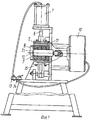
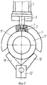
На фиг. 1 изображен общий вид устройства; на фиг. 2 - устройство зажима матрицы. In FIG. 1 shows a General view of the device; in FIG. 2 - device clamp matrix.
Устройство содержит станину 1, на которой укреплены разъемная матрица 2, состоящая из двух частей, соединенных одними концами шарнирно, а на других концах которых выполнены выступы 3, входящие в конусообразную выемку 4 скобы 5, которая жестко соединена со штоком 6 пневмопривода 7. Скоба 5 и пневмопривод 7 представляют собой механизм зажима матрицы. Пуансон включает формующую эластичную втулку 8, установленную на штоке 9, жестко связанном с пневмоприводом 10 его возвратно-поступательного движения, закрепленном на упоре 11, представляющим собой плиту, закрепленную на станине 1. В плите выполнено отверстие для штока 9 пуансона, на свободном конце которого выполнен фланец 12. Эластичная формующая втулка 8 может быть выполнена либо в виде цельной детали, либо в виде набора колец. The device comprises a frame 1, on which a
Пневмопривод 7 соединен шлангом с краном управления 13, пневмопривод 8 с краном управления 14. The
Матрица может охлаждаться, например водой, которая поступает в охлаждающие каналы (на чертеже не показаны) матрицы и отводится через штуцеры 15. The matrix can be cooled, for example by water, which enters the cooling channels (not shown in the drawing) of the matrix and is discharged through
Матрица 2 состоит из двух одинаковых частей 16 и 17, каждая из которых жестко соединена соответственно с рычагами 18 и 19, соединенных между собой с помощью шарнира 20.
Устройство работает следующим образом. The device operates as follows.
Полиэтиленовую трубу 21 разогревают, например в глицериновой или воздушной ванне до пластического состояния. Затем конец трубы, подлежащий формованию, надевают на формующий элемент. Пневмоприводом 7 опускается скоба 5, которая своими концами сжимает части 16 и 17 матрицы 2, выступы 3 которой входят в конусообразную выемку 4 скобы 5 и плотно замыкает матрицу. Пневмоприводом 10 шток 9 формующего элемента перемещается вправо, при этом фланец 12 перемещает эластичную формующую втулку 8, которая упирается в упор 11, и при дальнейшем перемещении штока 9 происходит сжатие и увеличение диаметра втулки 8, которая расширяет формуемую трубу 21 по форме матрицы 2. При этом происходит одновременное формование раструба и кольцевой канавки 22. После выдержки в течение, например 1-2 мин пневмопривод 10 возвращает формующий элемент в первоначальное положение, перемещая шток 9 в первоначальное положение, матрица раскрывается с помощью скобы 5, которая поднимается пневмоприводом 7 на расстояние, достаточное для выемки трубы с канавкой, и готовая труба с раструбом снимается. The polyethylene pipe 21 is heated, for example in a glycerin or air bath to a plastic state. Then the end of the pipe to be molded is put on the forming element. The
Устройство имеет простую конструкцию, надежно и просто в эксплуатации, высокопроизводительно. The device has a simple design, reliable and easy to operate, high performance.
Claims (2)
Priority Applications (1)
| Application Number | Priority Date | Filing Date | Title |
|---|---|---|---|
| SU4922403 RU2012503C1 (en) | 1991-03-21 | 1991-03-21 | Device for molding of a funnel with a ring recess in thermoplastic tubes |
Applications Claiming Priority (1)
| Application Number | Priority Date | Filing Date | Title |
|---|---|---|---|
| SU4922403 RU2012503C1 (en) | 1991-03-21 | 1991-03-21 | Device for molding of a funnel with a ring recess in thermoplastic tubes |
Publications (1)
| Publication Number | Publication Date |
|---|---|
| RU2012503C1 true RU2012503C1 (en) | 1994-05-15 |
Family
ID=21566913
Family Applications (1)
| Application Number | Title | Priority Date | Filing Date |
|---|---|---|---|
| SU4922403 RU2012503C1 (en) | 1991-03-21 | 1991-03-21 | Device for molding of a funnel with a ring recess in thermoplastic tubes |
Country Status (1)
| Country | Link |
|---|---|
| RU (1) | RU2012503C1 (en) |
-
1991
- 1991-03-21 RU SU4922403 patent/RU2012503C1/en active
Similar Documents
| Publication | Publication Date | Title |
|---|---|---|
| US4127632A (en) | Method of producing undercut tubular synthetic plastic articles | |
| JPS602168B2 (en) | Pipe fittings and their manufacturing method | |
| JPS6159894B2 (en) | ||
| US4350485A (en) | Device for moulding cylindrical pieces | |
| US3597517A (en) | Method of making plastic bellows | |
| US3260782A (en) | Press for shaping and curing pneumatic tires | |
| US4277231A (en) | Method and apparatus for pressure forming pipe bells | |
| US3832437A (en) | Method for forming hollow articles | |
| US3485908A (en) | Method for molding elongated elastomeric articles | |
| US2337857A (en) | Apparatus for shaping and vulcanizing pneumatic tires | |
| RU2012503C1 (en) | Device for molding of a funnel with a ring recess in thermoplastic tubes | |
| US3898315A (en) | Method for removing molds from articles with undercuts | |
| US3655323A (en) | Molding die structure | |
| US5127818A (en) | Apparatus for extending contour gaskets | |
| JPH0675932B2 (en) | Tire building equipment | |
| EP0490701B1 (en) | Compressed air blowing apparatus for use in green sand mold molding facility | |
| JPH05245843A (en) | Vulcanizing method for tires for road vehicles | |
| US4256449A (en) | Draw-forming of stretchable thermoplastic material into hollow articles | |
| US2486474A (en) | Extruding and processing apparatus | |
| US5353682A (en) | Closing and opening means for casting machine | |
| US2600958A (en) | Molding apparatus | |
| US5137679A (en) | Method of extending contour gaskets | |
| US7754132B1 (en) | Method of making a spool seal having a smooth sealing surface | |
| JPS61262112A (en) | Injection molding apparatus for preparing bellows molding | |
| CN223011705U (en) | A mold fixing and limiting device for paper cup forming |