RU2012189C1 - Crusher of sterns - Google Patents
Crusher of sterns Download PDFInfo
- Publication number
- RU2012189C1 RU2012189C1 SU4932070A RU2012189C1 RU 2012189 C1 RU2012189 C1 RU 2012189C1 SU 4932070 A SU4932070 A SU 4932070A RU 2012189 C1 RU2012189 C1 RU 2012189C1
- Authority
- RU
- Russia
- Prior art keywords
- drum
- shaft
- crusher
- guides
- service life
- Prior art date
Links
- 239000000969 carrier Substances 0.000 claims abstract description 5
- 238000005265 energy consumption Methods 0.000 claims description 5
- 230000001154 acute effect Effects 0.000 claims description 2
- 230000007423 decrease Effects 0.000 abstract description 2
- 230000000694 effects Effects 0.000 abstract 1
- 239000000126 substance Substances 0.000 abstract 1
- 238000005056 compaction Methods 0.000 description 2
- 235000013325 dietary fiber Nutrition 0.000 description 1
Images

Landscapes
- Crushing And Pulverization Processes (AREA)
Abstract
Description
Изобретение относится к сельскохозяйственному машиностроению, в частности к устройствам для измельчения кормов. The invention relates to agricultural machinery, in particular to devices for grinding feed.
Наиболее близким к предлагаемому по технической сущности и достигаемому результату является измельчитель кормов, особенностью конструкции которого является то, что измельчающий барабан установлен на шлицах с возможностью возвратно-поступательного движения вдоль оси вала и подпружинен с обеих сторон в направлении оси барабана, при этом пружины выполнены с регулируемой жесткостью. Closest to the proposed technical essence and the achieved result is a feed chopper, a design feature of which is that the chopper drum is mounted on the slots with the possibility of reciprocating motion along the shaft axis and is spring loaded on both sides in the direction of the drum axis, while the springs are made with adjustable stiffness.
При работе этого устройства резанием грубых кормов проводится нормальной силой с участием боковой. Боковая сила перемещает барабан вдоль оси вала, сжимая пружину, а нормальная сила скручивает вал, передаваясь последовательно от ножа на боковины барабана и далее на шлицы вала. При этом как боковая так и нормальная силы будут меняться по величине из-за того, что измельчаемый корм в зону резания подается относительно неравномерно, с различными физико-механическими свойствами. Непрерывно изменяющие боковая и нормальная силы будут способствовать быстрому износу места сочленения шлицевого вала с боковинами барабана. Это приводит к появлению стуков, вибрации и как следствие к снижению срока службы. Кроме того, действие нормальной силы снижает путь перемещения барабана в осевом направлении за счет возникновения дополнительного сопротивления, равного величине этой силы умноженной на коэффициент трения. В результате снижается доля скользящего резания и как следствие этого увеличивается расход энергии. When this device is working, the cutting of roughage is carried out by normal force with the participation of the side. The lateral force moves the drum along the axis of the shaft, compressing the spring, and the normal force twists the shaft, transmitted sequentially from the knife to the sides of the drum and further to the shaft splines. In this case, both the lateral and normal forces will vary in magnitude due to the fact that the crushed feed is supplied to the cutting zone relatively unevenly, with different physical and mechanical properties. Continuously changing lateral and normal forces will contribute to the rapid wear of the joint of the spline shaft with the drum sides. This leads to the appearance of knocks, vibration and, as a result, to a decrease in the service life. In addition, the action of a normal force reduces the axial direction of movement of the drum due to the occurrence of additional resistance equal to the value of this force times the coefficient of friction. As a result, the proportion of sliding cutting is reduced and, as a consequence, the energy consumption increases.
Целью настоящего изобретения является снижение удельного расхода энергии, повышение надежности и срока службы измельчителя. The aim of the present invention is to reduce specific energy consumption, increasing the reliability and service life of the grinder.
Указанная цель достигается тем, что в измельчителе кормов, содержащем подающий и нажимной транспортеры, противорежущую пластину и ножевой барабан, который установлен на валу с возможностью перемещения вдоль него, а с каждого торца барабан подпружинен относительно вала посредством пружин с регулируемой жесткостью, согласно изобретению режущий барабан установлен свободно на валу и снабжен водилами, одни концы которых жестко закреплены на валу, а другие размещены с возможностью перемещения в закрепленных на боковинах барабана направляющих, которые установлены под острым углом α к противорежущей пластине с образованием на развертке барабана между ними и спиралевых лезвиями ножей угла, равного 2α . This goal is achieved by the fact that in the feed chopper containing the feed and pressure conveyors, the opposing plate and the knife drum, which is mounted on the shaft with the ability to move along it, and from each end the drum is spring-loaded relative to the shaft by means of springs with adjustable stiffness, according to the invention, the cutting drum mounted freely on the shaft and equipped with carriers, some ends of which are rigidly fixed to the shaft, while others are placed with the possibility of movement in the guides fixed on the sides of the drum them, which are mounted at an acute angle α to the counter-plate on the drum to form between scan and spiralevyh knife blade angle of 2α.
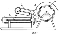
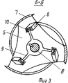
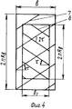
На фиг. 1 изображен предлагаемый измельчитель; на фиг. 2 - вид по стрелке А на фиг. 1; на фиг. 3 разрез по Б-Б на фиг. 2; на фиг. 4 - развертка барабана по ножам и направляющим. In FIG. 1 shows the proposed chopper; in FIG. 2 is a view along arrow A in FIG. 1; in FIG. 3 a section along BB in FIG. 2; in FIG. 4 - reamer drum on knives and guides.
Измельчитель кормов включает питатель, выполненный в виде подающего транспортера 1, над которым установлен нажимной транспортер 2. На выходе питателя расположена противорежущая пластина 3 и барабан 4. Последний имеет две боковины 5, к которым под углом τ жестко закреплены направляющие 6 и ножи 7. Причем они закреплены таким образом, что на развертке барабана направляющие 6 и спиральные лезвия ножей 7 образуют угол равный 2τ . Развертка барабана дана по ножам 7 с радиусом R δ и направляющим с радиусом Rв по ширине горловины В и длине направляющих В1. Боковины 5 установлены на валу 8 с возможностью радиального и осевого перемещения. Вращение барабана 4 и его осевое перемещение осуществляется под воздействием водил 9, одни концы которых жестко закреплены на валу 8, а другие, снабженные подшипниками 10, перемещаются по направляющим 6, выполненным в виде желоба. Боковины 5 с боков подпружинены вдоль оси барабана пружинами 11 и 12, которые установлены в обоймах 13 с возможностью регулировки их жесткости за счет корончатых гаек 14.The feed chopper includes a feeder, made in the form of a feed conveyor 1, above which a
Измельчитель кормов работает следующим образом. Корм, подлежащий измельчению, укладывают слоем на транспортер 1, который подает его к режущему барабану 4. При этом нажимной транспортер 2 предварительно подпрессовывает массу. Попадая между ножом 7 барабана 4 и противорежущей пластиной 3, корм вначале уплотняется до определенного предела, а затем перерезается. При уплотнении корма возникает боковая сила, которая заставляет переместиться барабан 4 вдоль оси вала 8 и сжать пружину 11. При перерезании измельчаемой массы пластические деформации меньше упругих, имеющих место при уплотнении корма, в результате чего пружина 11 перемещает барабан 4 вдоль оси вала 8 вправо. Пружина 12 при этом будет вначале разжиматься, а затем сжиматься, смягчая перемещение барабана. Перемещению барабана вдоль оси вала способствует также боковая сила, возникающая при воздействии водил и направляющих. Так как направляющие установлены под углом τ к противорежущей пластине таким образом, что на развертке барабана спиральные лезвия ножей и направляющих образуют угол равный 2 τ , то возникающая боковая сила совпадает по направлению с боковым усилием, возникающим при резании, в результате чего возрастает доля скользящего резания и как следствие этого расход энергии на измельчение корма. The feed chopper operates as follows. The feed to be ground is laid on a conveyor 1, which feeds it to the
Кроме того, учитывая, что крутящий момент от вала передается барабану не через жесткое шлицевое соединение, а водилами, подвижно связанными с направляющими, в результате чего часть передаваемого усилия гасится пружинами, то при работе измельчителя значительно снижаются ударные нагрузки, вибрация, повышается срок его службы. In addition, given that the torque from the shaft is transmitted to the drum not via a rigid spline connection, but by carriers that are movably connected to the guides, as a result of which part of the transmitted force is damped by springs, then when the grinder is operating, impact loads are significantly reduced, vibration is increased, and its service life is increased .
Предлагаемый измельчитель кормов позволяет дополнительно снизить на 10. . . 15% удельный расход энергии, повысить надежность и срок службы. (56) Авторское свидетельство СССР N 1579480, кл. А 01 F 29/00, 1988. The proposed feed chopper can be further reduced by 10.. . 15% specific energy consumption, improve reliability and service life. (56) Copyright certificate of the USSR N 1579480, cl. A 01 F 29/00, 1988.
Claims (1)
Priority Applications (1)
| Application Number | Priority Date | Filing Date | Title |
|---|---|---|---|
| SU4932070 RU2012189C1 (en) | 1991-04-29 | 1991-04-29 | Crusher of sterns |
Applications Claiming Priority (1)
| Application Number | Priority Date | Filing Date | Title |
|---|---|---|---|
| SU4932070 RU2012189C1 (en) | 1991-04-29 | 1991-04-29 | Crusher of sterns |
Publications (1)
| Publication Number | Publication Date |
|---|---|
| RU2012189C1 true RU2012189C1 (en) | 1994-05-15 |
Family
ID=21572306
Family Applications (1)
| Application Number | Title | Priority Date | Filing Date |
|---|---|---|---|
| SU4932070 RU2012189C1 (en) | 1991-04-29 | 1991-04-29 | Crusher of sterns |
Country Status (1)
| Country | Link |
|---|---|
| RU (1) | RU2012189C1 (en) |
Cited By (1)
| Publication number | Priority date | Publication date | Assignee | Title |
|---|---|---|---|---|
| RU2244414C1 (en) * | 2003-09-01 | 2005-01-20 | Брянская государственная сельскохозяйственная академия | Feed grinder |
-
1991
- 1991-04-29 RU SU4932070 patent/RU2012189C1/en active
Cited By (1)
| Publication number | Priority date | Publication date | Assignee | Title |
|---|---|---|---|---|
| RU2244414C1 (en) * | 2003-09-01 | 2005-01-20 | Брянская государственная сельскохозяйственная академия | Feed grinder |
Similar Documents
| Publication | Publication Date | Title |
|---|---|---|
| US4018392A (en) | Shredding machine | |
| US5911375A (en) | Chopper aggregate | |
| US4615343A (en) | Device for compressing tobacco in tobacco comminuting machines | |
| RU2012189C1 (en) | Crusher of sterns | |
| US4047673A (en) | Single-roll crusher | |
| CA1208156A (en) | Vibrating conveyor | |
| US4462309A (en) | Nutcracking machine | |
| KR100200949B1 (en) | Grain and red pepper grinder and its grinding method | |
| CN101209430A (en) | Elastic body coarse and intermediate crushing crusher | |
| US2318039A (en) | Rock crusher | |
| RU2127035C1 (en) | Feed mincer | |
| KR101327559B1 (en) | Food pulverrizer | |
| RU2366509C2 (en) | Material wet grinding device | |
| PL241362B1 (en) | Roller wood chipper with overload system | |
| CA1192884A (en) | Crushing device | |
| SU1694214A1 (en) | Arrangement for comminuting materials | |
| SU1581380A2 (en) | Crusher for metal chips | |
| SU1165355A1 (en) | Fodder production line for animals and poultry | |
| KR200145932Y1 (en) | Grain and vegetable grinder | |
| CN2137982Y (en) | Crushing machine for filtering cake | |
| SU1366204A1 (en) | Disk mill | |
| SU1045918A1 (en) | Apparatus for crushing | |
| SU1076025A1 (en) | Fodder mincer | |
| RU2036725C1 (en) | Roll-type press for disintegration and softening mineral raw materials | |
| SU912113A1 (en) | Bale crusher |