RU2012155C1 - Thermal imager - Google Patents
Thermal imager Download PDFInfo
- Publication number
- RU2012155C1 RU2012155C1 SU4906500A RU2012155C1 RU 2012155 C1 RU2012155 C1 RU 2012155C1 SU 4906500 A SU4906500 A SU 4906500A RU 2012155 C1 RU2012155 C1 RU 2012155C1
- Authority
- RU
- Russia
- Prior art keywords
- output
- input
- amplifier
- controller
- converter
- Prior art date
Links
- 238000003860 storage Methods 0.000 claims abstract description 20
- 230000027455 binding Effects 0.000 claims description 22
- 238000009739 binding Methods 0.000 claims description 22
- 238000005070 sampling Methods 0.000 claims description 16
- 230000006641 stabilisation Effects 0.000 claims description 8
- 238000011105 stabilization Methods 0.000 claims description 8
- 238000009529 body temperature measurement Methods 0.000 abstract description 5
- 230000000694 effects Effects 0.000 abstract description 4
- 238000001931 thermography Methods 0.000 abstract description 3
- 239000000126 substance Substances 0.000 abstract 1
- 230000008859 change Effects 0.000 description 8
- 238000010586 diagram Methods 0.000 description 6
- 238000000034 method Methods 0.000 description 5
- 230000016776 visual perception Effects 0.000 description 5
- IJGRMHOSHXDMSA-UHFFFAOYSA-N Atomic nitrogen Chemical compound N#N IJGRMHOSHXDMSA-UHFFFAOYSA-N 0.000 description 4
- 230000015572 biosynthetic process Effects 0.000 description 4
- 230000035945 sensitivity Effects 0.000 description 4
- 238000012546 transfer Methods 0.000 description 4
- 238000004458 analytical method Methods 0.000 description 3
- 230000009467 reduction Effects 0.000 description 3
- 238000003491 array Methods 0.000 description 2
- 238000011088 calibration curve Methods 0.000 description 2
- 230000003247 decreasing effect Effects 0.000 description 2
- 238000013461 design Methods 0.000 description 2
- 230000008030 elimination Effects 0.000 description 2
- 238000003379 elimination reaction Methods 0.000 description 2
- 238000009434 installation Methods 0.000 description 2
- 239000007788 liquid Substances 0.000 description 2
- 239000000203 mixture Substances 0.000 description 2
- 238000012544 monitoring process Methods 0.000 description 2
- 229910052757 nitrogen Inorganic materials 0.000 description 2
- 238000001208 nuclear magnetic resonance pulse sequence Methods 0.000 description 2
- 230000035515 penetration Effects 0.000 description 2
- 230000008569 process Effects 0.000 description 2
- 230000005855 radiation Effects 0.000 description 2
- 238000012935 Averaging Methods 0.000 description 1
- 238000007792 addition Methods 0.000 description 1
- 239000012080 ambient air Substances 0.000 description 1
- 230000000903 blocking effect Effects 0.000 description 1
- 238000009835 boiling Methods 0.000 description 1
- 238000004891 communication Methods 0.000 description 1
- 230000006870 function Effects 0.000 description 1
- 229910052732 germanium Inorganic materials 0.000 description 1
- GNPVGFCGXDBREM-UHFFFAOYSA-N germanium atom Chemical compound [Ge] GNPVGFCGXDBREM-UHFFFAOYSA-N 0.000 description 1
- 230000003993 interaction Effects 0.000 description 1
- 238000004519 manufacturing process Methods 0.000 description 1
- 238000005259 measurement Methods 0.000 description 1
- 230000003287 optical effect Effects 0.000 description 1
- 230000005693 optoelectronics Effects 0.000 description 1
- 230000008520 organization Effects 0.000 description 1
- 238000004091 panning Methods 0.000 description 1
- 230000008447 perception Effects 0.000 description 1
- 238000012545 processing Methods 0.000 description 1
- 239000000047 product Substances 0.000 description 1
- 230000010349 pulsation Effects 0.000 description 1
- 238000009877 rendering Methods 0.000 description 1
- 238000011160 research Methods 0.000 description 1
- 230000003595 spectral effect Effects 0.000 description 1
- 238000001228 spectrum Methods 0.000 description 1
- 230000000087 stabilizing effect Effects 0.000 description 1
- 239000013589 supplement Substances 0.000 description 1
- 230000001360 synchronised effect Effects 0.000 description 1
- 238000012360 testing method Methods 0.000 description 1
- 238000012549 training Methods 0.000 description 1
- 230000007704 transition Effects 0.000 description 1
- 230000000007 visual effect Effects 0.000 description 1
- 238000012800 visualization Methods 0.000 description 1
Images
Landscapes
- Radiation Pyrometers (AREA)
Abstract
Description
Изобретение предназначено для визуального наблюдения тепловых изображений различных объектов посредством бесконтактной оптико-цифровой регистрации собственного и отраженного теплового излучения и отображения теплового "портрета" в видеоконтрольном блоке. The invention is intended for visual observation of thermal images of various objects through non-contact optical-digital registration of intrinsic and reflected thermal radiation and display of a thermal "portrait" in a video control unit.
Известен тепловизор (см. М. М. Мирошников. Теоретические основы оптико-электронных приборов. Учебное пособие для приборостроительных вузов. - Л. : Машиностроение, 1983, с. 598, рис. 360), содержащий зеркало, объектив, фотоприемник, предусилитель. Причем зеркало установлено перед объективом. A well-known thermal imager (see M. M. Miroshnikov. Theoretical Foundations of Optoelectronic Devices. A Training Manual for Instrument-Making Universities. - L.: Mashinostroenie, 1983, p. 598, Fig. 360), containing a mirror, lens, photodetector, preamplifier. Moreover, the mirror is installed in front of the lens.
Недостатками данного устройства являются отсутствие привязки уровня сигнала к эталонному источнику (например, черному телу), что не позволяет измерить температуру исследуемого объекта, а также невысокое качество восприятия тепловой картины, особенно при использовании фотоприемника малой чувствительности в условиях нестабильности растра, вызванного неидеальностью вращения зеркала. The disadvantages of this device are the lack of binding of the signal level to a reference source (for example, a black body), which does not allow measuring the temperature of the object under study, as well as the poor quality of perception of the thermal picture, especially when using a low-sensitivity photodetector in conditions of raster instability caused by imperfect mirror rotation.
Наиблее близким по технической сущности к предложенному техническому решению является двухспектральный тепловизор, содержащий эталонный источник, находящийся в тепловом контакте с датчиком температуры, а также два идентичных канала (см. Ж. Госсорг. Инфракрасная термография. Основы, техника применения. М. : Мир, 1988, с. 274, с. 362, 379). Каждый канал содержит объектив, привод вращения, последовательно соединенные фотоприемник, предусилитель, видеоусилитель, блок привязки уровня, устройство выборки и хранения, аналого-цифровой преобразователь и видеоконтрольный блок. Развертка (т. е. строчное сканирование и формирование кадра) выполняется за счет двух скрещенных многоплоскостных зеркальных барабанов (призм). The closest in technical essence to the proposed technical solution is a two-spectrum thermal imager containing a reference source that is in thermal contact with the temperature sensor, as well as two identical channels (see J. Gossorg. Infrared thermography. Basics, application technique. M.: Mir, 1988, p. 274, p. 362, 379). Each channel contains a lens, a rotation drive, a photodetector, a preamplifier, a video amplifier, a level binding unit, a sampling and storage device, an analog-to-digital converter, and a video control unit. Scanning (i.e. line scanning and frame formation) is performed by two crossed multi-plane mirror drums (prisms).
Это устройство обеспечивает более высокое качество визуального восприятия тепловой картины за счет того, что зеркальные вращающиеся элементы развертки находятся внутри корпуса тепловизора за объективом и имеют более обтекаемую форму, чем простое зеркало (отсутствует "эффект вентилятора", когда скорость вращения зеркала существенно зависит от его взаимодействия с окружающим воздухом, а значит от конструкции тепловизора, окружающей температуры, атмосферного давления и т. д. ). This device provides a higher quality of visual perception of the thermal picture due to the fact that the mirror rotating scan elements are located inside the thermal imager body behind the lens and have a more streamlined shape than a simple mirror (there is no “fan effect” when the speed of rotation of the mirror substantially depends on its interaction with ambient air, which means from the design of the thermal imager, ambient temperature, atmospheric pressure, etc.).
Однако оптико-механическая система прототипа требует очень высокого качества изготовления и юстировки вращающихся зеркальных призм (ибо это определяет длину строк, их параллельность, расстояние между строками и проч), иначе даже при очень высокой стабильности привода вращения растр будет сильно искажаться. Это приводит к высокой сложности и стоимости самого устройства. В устройстве (прототипе), которое является двухканальным, обеспечивается повышение качества визуального восприятия тепловой картины за счет сопоставления изображений в двух различных спектральных интервалах ИК-диапазона. Однако двухканальность дополнительно усложняет и существенно удорожает его (два комплекта дорогостоящей германиевой оптики, два прецезионных сканера с вращающимися зеркальными призмами и т. д). Тем не менее неидеальности привода вращения приводят к нестабильности растра, что, особенно если контрасты наблюдаемых объектов близки к предельной чувствительности фотоприемников, ограничивает область применения тепловизора и снижает качество визуального восприятия тепловой картины. However, the optical-mechanical system of the prototype requires a very high quality of manufacturing and aligning rotating mirror prisms (because this determines the length of the lines, their parallelism, the distance between the lines, etc.), otherwise even with a very high stability of the rotation drive, the raster will be greatly distorted. This leads to high complexity and cost of the device itself. In the device (prototype), which is a two-channel, provides an increase in the quality of visual perception of the thermal picture by comparing the images in two different IR spectral ranges. However, the two-channel system additionally complicates and significantly increases its cost (two sets of expensive germanium optics, two precision scanners with rotating mirror prisms, etc.). Nevertheless, imperfections of the rotation drive lead to raster instability, which, especially if the contrasts of the observed objects are close to the maximum sensitivity of the photodetectors, limits the scope of the thermal imager and reduces the quality of the visual perception of the thermal picture.
Кроме того, в этом устройстве нельзя оперативно изменять поле зрения системы (изменение производится только сменой объектива), а также осуществлять форматирование изображения (т. е. задавать число строк в изображении и число элементов в строке) по желанию пользователя. В данном устройстве также возможно измерение температуры, поскольку привязка осуществляется с помощью датчика температуры эталонного источника (внутреннего абсолютно черного тела). Сигнал термокомпенсации вводится в каждом из измерительных трактов после блока привязки уровня с помощью соответствующих автономных компенсационных каналов, что приводит к появлению дополнительных смещений сигналов (т. е. к ошибкам в измерении температуры) за счет временных дрейфов в термокомпенсационных каналах и неидентичности сигнального и термокомпенсационного каналов для каждого диапазона. Кроме того, в рассматриваемой схеме устройства выборки и хранения (УВХ) размещены после соответствующих схем привязки уровня. В этом случае погрешности смещения УВХ (временной дрейф) поступают на аналого-цифровые преобразователи каждого тракта в виде термонезависимых составляющих сигналов и определяют в них общие ошибки измерения температуры, которые являются несепарабельными по отношению к изменению температуры, так как включает в себя и остаточные ошибки термокомпенсации. In addition, in this device it is impossible to quickly change the field of view of the system (the change is made only by changing the lens), and also to format the image (i.e., set the number of lines in the image and the number of elements in the line) at the request of the user. In this device, it is also possible to measure temperature, since the binding is carried out using the temperature sensor of the reference source (internal black body). The temperature compensation signal is introduced in each of the measuring paths after the level binding unit using the corresponding autonomous compensation channels, which leads to the appearance of additional signal offsets (i.e., errors in the temperature measurement) due to temporary drifts in the temperature compensation channels and the non-identity of the signal and temperature compensation channels for each range. In addition, in the considered scheme, the sampling and storage devices (SEC) are placed after the corresponding level binding schemes. In this case, the error of the UVC bias (time drift) arrives at the analog-to-digital converters of each path in the form of thermally independent components of the signals and determines in them the general errors of temperature measurement, which are inseparable with respect to the temperature change, since it also includes the residual errors of thermal compensation .
Стабилизация абсолютной температуры приемников осуществляется при температуре кипения жидкого азота с помощью криостатирования, которое также обеспечивает высокую чувствительность тепловизора, необходимую, например при проведении медицинских исследований. Однако во многих случаях (например, при контроле некоторых технологических процессов) не требуются дорогостоящие тепловизоры с высокочувствительными приемниками. При этом необходимость стабилизации абсолютной температуры каждого приемника сохраняется, но обеспечение ее, как в прототипе, с помощью криостатирования становится фактором дополнительного усложнения и удорожания устройства, а также ограничивает область возможных применений из-за его неавтономности, связанной с регулярной дозаправкой криостата жидким азотом. Stabilization of the absolute temperature of the receivers is carried out at the boiling point of liquid nitrogen using cryostatting, which also provides high sensitivity of the thermal imager, necessary, for example, when conducting medical research. However, in many cases (for example, when monitoring some technological processes), expensive thermal imagers with highly sensitive receivers are not required. At the same time, the need to stabilize the absolute temperature of each receiver remains, but ensuring it, as in the prototype, with the help of cryostation becomes a factor of additional complication and cost of the device, and also limits the scope of possible applications due to its non-autonomy associated with regular refueling of the cryostat with liquid nitrogen.
Целью изобретения является повышение информативности изображения путем управления полем зрения. The aim of the invention is to increase the information content of the image by controlling the field of view.
Соответствие заявляемого технического решения критерию "существенные отличия" определяется тем, что благодаря признакам, отличающим предлагаемое устройство от его прототипа, у устройства появились новые свойства: уменьшение ошибки термокомпенсации за счет устранения вклада в нее термонезависимого смещения (временного дрейфа); устранение вклада термонезависимой погрешности смещения устройства выборки и хранения в общую ошибку измерения температуры; представление тепловой картины на фоне видимого изображения при упрощении структуры тепловизора и стабилизации растра; возможность оперативной смены формата изображения; возможность оперативного изменения поля зрения тепловизора. The compliance of the proposed technical solution with the criterion of "significant differences" is determined by the fact that due to the features distinguishing the proposed device from its prototype, the device has new properties: reduction of thermal compensation error due to elimination of the contribution of a thermally independent bias (time drift) to it; elimination of the contribution of the thermally independent bias error of the sampling and storage device to the total temperature measurement error; representation of the thermal picture against the background of the visible image while simplifying the structure of the thermal imager and stabilizing the raster; the ability to quickly change the image format; the ability to quickly change the field of view of the thermal imager.
Данные свойства, обуславливающие достижение цели изобретения, отсутствуют у всех известных устройств аналогичного назначения и определяют преимущества предлагаемого технического решения по отношению к прототипу, если предлагаемое устройство сравнивать с прототипом (или другими аналогичными устройствами) при равных условиях, включающих, например, равную чувствительность фотоприемников и одинаковую собственную стабильность приводов вращения (собственно привод без элементов развертки). В частности, форматирование, т. е. задание числа строк в изображении и числа элементов (отсчетов) в строке, означает вариацию поля зрения при фиксированном пространственном разрешении. Это свойство является новым для предлагаемого устройства. Оно полезно и необходимо при использовании тепловизора, например, для ряда задач теплового контроля (в частности, теплового контроля качества сборки каких-либо электронных блоков, модулей и других изделий электроники), когда объекты контроля могут иметь различные размеры. В таких случаях при использовании устройств, соответствующих прототипу, и других тепловизионных устройств возникает необходимость перемещения тепловизора (приближения или удаления) или смены объективов, что не всегда возможно и поэтому ограничивает сферу их применения. В предлагаемом устройстве возможность вариации поля зрения позволяет избежать попадания в кадр соседних объектов (например, контролируемых блоков), если они располагаются рядом (например, на конвейере) и имеют размеры, меньше, чем полное поле зрения тепловизора. These properties that determine the achievement of the purpose of the invention are absent in all known devices of a similar purpose and determine the advantages of the proposed technical solution in relation to the prototype, if the proposed device is compared with the prototype (or other similar devices) under equal conditions, including, for example, equal sensitivity of photodetectors and the same intrinsic stability of rotation drives (the drive itself without scan elements). In particular, formatting, i.e., setting the number of lines in an image and the number of elements (samples) in a line, means the variation of the field of view at a fixed spatial resolution. This property is new to the proposed device. It is useful and necessary when using a thermal imager, for example, for a number of thermal control tasks (in particular, thermal control of the assembly quality of any electronic units, modules, and other electronics products), when the monitoring objects can have different sizes. In such cases, when using devices corresponding to the prototype, and other thermal imaging devices, it becomes necessary to move the thermal imager (zoom in or out) or change lenses, which is not always possible and therefore limits the scope of their application. In the proposed device, the possibility of varying the field of view avoids neighboring objects (for example, controlled units) getting into the frame if they are located nearby (for example, on a conveyor) and have dimensions smaller than the total field of view of the thermal imager.
При работе с объектами, тепловой контраст которых близок к предельной чувствительности фотоприемников, тепловая картина как в прототипе, так и в предложенном устройстве превращается в совокупность нескольких пятен от наиболее горячих точек (объектов). Это ограничивает область применения прототипа, так как затрудняет привязку пятен к конкретным точкам наблюдаемого объекта, особенно в условиях нестабильности растра, приводящей к геометрическим искажениям внутри кадра (затрудняет измерение расстояний, оценивание размеров и проч. ) и флуктуациям геометрических параметров наблюдаемого изображения от кадра к кадру (затрудняет измерения пространственных характеристик, ухудшает визуальное восприятие). У предложенного устройства эти недостатки отсутствуют, так как "пятна" тепловой картины накладываются на видимое изображение. Таким образом, возможность форматирования изображения посредством вариации поля зрения за счет задания числа строк и числа элементов в строке обеспечивает расширение области применения предложенного тепловизора. When working with objects whose thermal contrast is close to the maximum sensitivity of photodetectors, the thermal picture both in the prototype and in the proposed device turns into a combination of several spots from the hottest spots (objects). This limits the scope of the prototype, since it complicates the binding of spots to specific points of the observed object, especially in conditions of instability of the raster, which leads to geometric distortions inside the frame (makes it difficult to measure distances, size estimation, etc.) and fluctuations in the geometric parameters of the observed image from frame to frame (complicates the measurement of spatial characteristics, worsens visual perception). The proposed device does not have these disadvantages, since the "spots" of the thermal picture are superimposed on the visible image. Thus, the possibility of formatting the image by varying the field of view by setting the number of lines and the number of elements per line provides an extension of the scope of the proposed thermal imager.
При фиксированном формате (т. е. зафиксированном числе элементов в строке) увеличение расстояния между отсчетами (элементами в строке) обеспечивает расширение поля зрения вдоль строк, а уменьшение этого расстояния - соответствующее сужение поля. При максимальной длине строк (максимальное число отсчетов) увеличение расстояния между отсчетами создает эффект панарамирования, что означает представление на экране тепловизора сжатой тепловой картины из сдвинутых друг к другу отсчетов, снятых в расширенном угловом секторе. Это позволяет наблюдать и качественно оценивать тепловой режим протяженного объекта (например, кабельных и воздушных линий электропередачи, энергетического, теплотехнического и другого оборудования) для выбора и подбробного анализа теплового портрета в том или ином конкретном месте. With a fixed format (i.e., a fixed number of elements in a row), increasing the distance between samples (elements in a row) provides an extension of the field of view along the lines, and decreasing this distance - a corresponding narrowing of the field. With the maximum length of the lines (maximum number of samples), increasing the distance between the samples creates a panning effect, which means that a compressed thermal picture is shown on the imager screen from shifted samples taken in an extended angular sector. This allows you to observe and qualitatively evaluate the thermal regime of an extended object (for example, cable and overhead power lines, energy, heat engineering and other equipment) for the selection and detailed analysis of a thermal portrait in a particular place.
При уменьшении расстояния между элементами в строке создается эффект одномерной телевизионной лупы, так как при этом не только представляется на экране растянутая вдоль строк тепловая картина, снятая в суженном угловом секторе, но и обеспечивается повышение разрешающей способности вдоль строк при частичном перекрытии отсчетов. При значительном уменьшении расстояния между элементами в строке (перекрытие отсчетов более 50% ) прямая визуализация теплового портрета сопровождается значительными искажениями. Однако при этом имеется дополнительная возможность повышения отношения сигнал/шум в изображении за счет (при внесении необходимых дополнений в программу контроллера) усреднения по нескольким соседним отсчетам и визуализации такого числа элементов в строке, которое соответствует угловому расстоянию между крайними отсчетами в строке, деленному на угловой размер самого отсчета. Таким образом, возможность изменения расстояния между отсчетами в строках предлагаемого тепловизора обеспечивает как удобство пользователя, так и расширение области его применения. When the distance between the elements in the line is reduced, the effect of a one-dimensional television magnifier is created, since not only does the thermal picture stretched along the lines taken in the narrowed angular sector appear on the screen, but also an increase in the resolution along the lines with partial overlap of the readings is provided. With a significant reduction in the distance between the elements in the line (overlapping readings of more than 50%), direct visualization of the thermal portrait is accompanied by significant distortions. However, there is an additional possibility of increasing the signal-to-noise ratio in the image due to (upon making the necessary additions to the controller program) averaging over several adjacent samples and visualizing such a number of elements in a row that corresponds to the angular distance between the extreme samples in a row divided by the angular the size of the reference itself. Thus, the ability to change the distance between the samples in the lines of the proposed thermal imager provides both user convenience and the expansion of its scope.
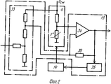
На фиг. 1 изображена структурная схема устройства; на фиг. 2 приведен усилитель-преобразователь; на фиг. 3 и 4 - временные диаграммы, иллюстрирующие работу тепловизора; на фиг. 5 - приведен пример выполнения диска одного из возможных вариантов датчика положения зеркала; на фиг. 6 - градуировочная кривая; на фиг. 7 - упрощенная структурная схема блока привязки уровня, на фиг. 8 - пример технической реализации блока привязки уровня; на фиг. 9 - схема программы работы тепловизора. In FIG. 1 shows a block diagram of a device; in FIG. 2 shows the amplifier-converter; in FIG. 3 and 4 are timing diagrams illustrating the operation of the thermal imager; in FIG. 5 - shows an example of a disk of one of the possible mirror position sensor options; in FIG. 6 - calibration curve; in FIG. 7 is a simplified block diagram of a level binding unit; FIG. 8 is an example of a technical implementation of a level binding unit; in FIG. 9 is a diagram of a program of work of a thermal imager.
Предлагаемое устройство (см. фиг. 1 и 2) содержит зеркало 1, объектив 2, блок светоделения 3, первый и второй фотоприемники 4 и 5, датчик положения зеркала 6, привод вращения 7, шаговый привод 8, поворотную платформу 9, эталонный источник 10, датчик температуры 11, модулятор 12, усилитель-преобразователь 13, термоэлектрический охладитель 14, предусилитель 15, видеоусилитель 16, первый и второй блоки выборки и хранения 17 и 18, блок привязки уровня 19, первый и второй аналого-цифровые преобразователи 20 и 21, контроллер 22, генератор тактовых импульсов 23, первый формирователь импульсов 24, второй формирователь импульсов 25, первый и второй счетчики 26 и 27, регистр 28, третий формирователь импульсов 29, управляемый делитель 30, четвертый формирователь импульсов 31, видеоконтрольный блок 32, смеситель 33, дифференциальный усилитель 34, усилитель обратной связи 35, резистор 36. The proposed device (see Fig. 1 and 2) contains a
Эталонный источник 10, зеркало 1, объектив 2, блок светоделения 3 и первый и второй фотоприемники 4 и 5 оптически связаны, первый фотоприемник 4, усилитель-преобразователь 13, первый блок выборки и хранения 17, блок привязки уровня 19 и первый аналого-цифровой преобразователь 20 соединены последовательно, второй фотоприемник 5, предусилитель 15, видеоусилитель 16, второй блок выборки и хранения 18 и второй аналого-цифровой преобразователь 21 соединены последовательно, датчик температуры 11 находится в тепловом контакте с эталонным источником 10, выход датчика температуры 11 подключен к первому входу модулятора 12, выход которого соединен с вторым входом усилителя-преобразователя 13, выход термостабилизации усилителя-преобразователя 13 подключен к входу термоэлектрического охладителя 14, который находится в тепловом контакте с первым фотоприемником 4.
Выход датчика положения зеркала 6 соединен со входами первого формирователя импульсов 24, второго формирователя импульсов 25 и с первым входом контроллера 22. Генератор тактовых импульсов 23, управляемый делитель 30, второй счетчик 27 и четвертый формирователь импульсов 31 соединены последовательно, первый и второй входы первого счетчика 26 подключены к выходам генератора тактовых импульсов 23 и первого формирователя импульсов 24 соответственно, а выход соединен с первым входом регистра 28, второй вход регистра 28 подключен к выходу второго формирователя импульсов 25, а выход соединен с вторым входом второго счетчика 27, первый и второй входы третьего формирователя импульсов 29 подключены к выходам второго формирователя импульсов 25 и второго счетчика 27 соответственно, а выход соединен с управляющим входом второго счетчика 27. Выход четвертого формирователя импульсов 31 подключен к вторым входам контроллера 22 и первого и второго блоков выборки и хранения 17 и 18, третий и четвертый входы контроллера 22 соединены с выходами первого и второго аналого-цифровых преобразователей 20 и 21 соответственно, первый выход контроллера подключен к вторым входам первого и второго аналого-цифровых преобразователей 20 и 21, второй, третий, четвертый, пятый и шестой выходы контроллера 22 подключены соответственно, к входу видеоконтрольного блока 32, к управляющему входу шагового привода 8, к входу управления управляемого делителя 30, к второму входу модулятора 12 и к второму входу блока привязки уровня 19. The output of the mirror position sensor 6 is connected to the inputs of the first pulse shaper 24, the second pulse shaper 25 and to the first input of the controller 22. The clock generator 23, the controlled divider 30, the second counter 27 and the fourth pulse shaper 31 are connected in series, the first and second inputs of the first counter 26 are connected to the outputs of the clock generator 23 and the first pulse shaper 24, respectively, and the output is connected to the first input of the register 28, the second input of the register 28 is connected to the output of the second form pulse generator 25, and the output is connected to the second input of the second counter 27, the first and second inputs of the third pulse shaper 29 are connected to the outputs of the second pulse shaper 25 and the second counter 27, respectively, and the output is connected to the control input of the second counter 27. The output of the fourth pulse shaper 31 connected to the second inputs of the controller 22 and the first and second sampling and
Усилитель-преобразователь 13 содержит смеситель 33, дифференциальный усилитель 34, усилитель обратной связи 35 и резистор 36, причем выход смесителя 33 подключен к инвертирующему входу дифференциального усилителя 34, дифференциальный усилитель 34 и усилитель обратной связи 35 соединены последовательно, резистор 36 включен между инвертирующим входом и выходом дифференциального усилителя 34. The amplifier-
Выходная ось шагового привода 8 жестко соединена с поворотной платформой 9, на которой механически крепятся эталонный источник 10, датчик температуры 11, привод вращения 7 с жестко закрепленным на нем зеркалом 1, датчик положения зеркала 6, объектив 2, блок светоделения 3, первый и второй фотоприемники 4 и 5, предусилитель 15, усилитель-преобразователь 13, термоэлектрический охладитель 14 и модулятор 12. The output axis of the
Устройство работает следующим образом. The device operates as follows.
Отраженное от зеркала 1 оптическое излучение объекта через объектив 2 и блок светоделения 3 поступает на светочувствительные площадки первого и второго фотоприемников 4 и 5. Первый фотоприемник 4, выполненный на основе терморезистора, работает в тепловом диапазоне, а второй фотоприемник 5 - в видимом. Сигнал с выхода первого фотоприемника 4 проходит через усилитель-преобразователь 13 на первый блок выборки и хранения 17, выходной сигнал которого корректируется в блоке привязки уровня 19, затем оцифровывается в первом аналого-цифровом преобразователе 20 и подается на третий вход 40 контроллера 22. Сигналы с выхода второго фотоприемника 5 проходят через предусилитель 15 и видеоусилитель 16 на второй блок выборки и хранения 18, выходной сигнал которого оцифровывается во втором аналого-цифровом преобразователе 21 и подается на четвертый вход 41 контроллера 22. Зеркало 1, вращаемое приводом вращения 7, обеспечивает развертку изображения по строке (см. фиг. 4, поз. 58). При этом в поле зрения первого и второго фотоприемников 4 и 5 последовательно попадают эталонный источник 10, в качестве которого можно использовать черное тело, и наблюдаемый объект. Кадровая развертка реализуется путем вращения шаговым приводом 8 поворотной платформы 9. Контроллер 22 управляет кадровой разверткой, выдавая сигналы с выхода 49 на управляющий вход шагового привода 8 (для чего в приводе предусмотрены ключи). Таким образом, в запоминающее устройство, входящее в состав контроллера 22, записываются два цифровых массива, соответствующих видимому и тепловому изображениям. По окончании формирования массивов тепловое изображение контрастируется в контроллере 22 с помощью программной процедуры бинаризации (в простейшем варианте производится поэлементное сравнение изображения с пороговым значением, хранящимся в соответствующей ячейке памяти контроллера 22 и допускающем оперативное изменение) и затем смешивается программно с видимым (например черно-белым) изображением так, чтобы на экране видеоконтрольного блока 32 воспроизводилось изображение видимого канала с окрашенными пятнами, соответствующими нагретым участкам анализируемого объекта, выделенным процедурой бинаризации теплового изображения. Указанная процедура дает возможность пространственной привязки нагретого объекта по деталям видимого изображения даже при использовании малочувствительного приемника, что равносильно получению теплового изображения с высоким температурным разрешением. The optical radiation of the object reflected from the
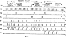
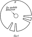
Синхронизация работы предлагаемого устройства обеспечивается датчиком положения зеркала 6, который может быть выполнен в виде расположенных друг напротив друга лампочки 37 и фотодиода 38, между которыми размещен диск 39 (см. фиг. 3 ) с четырьмя отверстиями (для одностороннего зеркала), жестко закрепленный на оси привода вращения 7. При вращении диска 39 в момент прохождения каждого отверстия между лампочкой 37 и фотодиодом 38 вырабатывается синхроимпульс (см. фиг. 3 и 4, поз. 50), который с выхода фотодиода 38 (имеет на своем выходе формирователь импульсов) поступает на первый вход 46 контроллера 22 и входы первого и второго формирователей импульсов 24 и 25. The operation of the proposed device is synchronized by a mirror position sensor 6, which can be made in the form of opposite lamps 37 and a photodiode 38, between which there is a disk 39 (see Fig. 3) with four holes (for a one-way mirror), rigidly fixed to axis of rotation drive 7. During rotation of the
Нестабильность вращения зеркала 1 может привести к нестабильности растра, т. е. j-е отсчеты разных (в том числе соседних) строк (j-номер отсчета в строке) будут сниматься при различных угловых положениях зеркала 1. Стабилизация растра осуществляется следующим образом. Первый счетчик 26, на счетный вход которого поступают импульсы (см. фиг. 3, поз. 51) с выхода генератора тактовых импульсов 23, производит подсчет числа импульсов, укладывающихся в измерительный интервал между задним и передним фронтами соседних импульсов с выхода датчика положения зеркала 6 (см. фиг. 3, поз. 50). При этом первый счетчик 26 обнуляется импульсом с выхода первого формирователя импульсов 24 (см. фиг. 3, поз. 52), а в регистр 28 с выхода первого счетчика 26 загружается двоичный код, соответствующий числу тактовых импульсов, укладывающихся между соседними отсчетами изображения на строке. The instability of rotation of
Импульс загрузки (см. фиг. 3, поз. 53) вырабатывается вторым формирователем импульсов 25. При необходимости передний фронт импульсов загрузки можно привязать к переднему фронту тактовых импульсов (см. фиг. 3, поз. 51). В этом случае второй формирователь импульсов 25 может быть выполнен на основе D-триггера (см. Справочник по интегральным микросхемам. ) Под ред. Б. В. Тарабрина. М. : Энергия, 1980, с. 725, рис. 5-228), на входы D и С которого подаются импульсы с выходов датчика положения зеркала 6 и генератора тактовых импульсов 23 соответственно. Второй счетчик 27 (здесь может быть использован счетчик с выходом переноса, например 155ИЕ7), работающий на уменьшение, вырабатывает импульсную последовательность (см. фиг. 3, поз. 54) с периодом, определяющим период съема информации по строке изображения. На первый вход второго счетчика 27 (счетный вход) поступают импульсы с управляемого делителя 30, который может быть реализован на основе делителя частоты с переключаемым коэффициентом деления (например, 561ИЕ15) (см. Бирюков С. А. . Цифровые устройства на МОП-интегральных микросхемах. М. : Радио и связь, 1990, с. 33-34). The load pulse (see Fig. 3, pos. 53) is generated by the second pulse shaper 25. If necessary, the leading edge of the load pulses can be linked to the leading edge of the clock pulses (see Fig. 3, pos. 51). In this case, the second pulse shaper 25 can be made on the basis of the D-trigger (see. Reference on integrated circuits.) Ed. B.V. Tarabrina. M.: Energy, 1980, p. 725, fig. 5-228), to the inputs D and C of which pulses are supplied from the outputs of the mirror position sensor 6 and the clock generator 23, respectively. The second counter 27 (a counter with a transfer output, for example, 155IE7 can be used here), which works on decreasing, produces a pulse sequence (see Fig. 3, item 54) with a period that determines the period of information retrieval on the image line. The first input of the second counter 27 (counting input) receives pulses from a controlled divider 30, which can be implemented on the basis of a frequency divider with a switchable division ratio (for example, 561IE15) (see Biryukov S. A. Digital devices on MOS integrated circuits . M.: Radio and communication, 1990, S. 33-34).
На второй вход (вход данных) второго счетчика 27 подается код с регистра 28, который загружается импульсами с выхода третьего формирователя импульсов 29 (фиг. 3, поз. 55). При каждом цикле загрузки кода во второй счетчик 27 "старая" информация забывается. С выхода 47 контроллера 22 на вход управления управляемого делителя 30 (выводы 2 - 11, 13 - 22 микросхемы 561ИЕ15) по шине поступают сигналы, обеспечивающие установку требуемого коэффициента деления частоты сигнала с выхода генератора тактовых импульсов 23 (см. фиг. 3, поз. 51), который приходит на вход управляемого делителя 30. При этом коэффициент деления (устанавливается программно с клавиатуры, входящей в состав контроллера 22) определяет расстояние между соседними отсчетами изображения по строке а в итоге - поле зрения тепловизора. A code from register 28 is supplied to the second input (data input) of the second counter 27, which is loaded by pulses from the output of the third pulse shaper 29 (Fig. 3, item 55). With each cycle of loading the code into the second counter 27, the "old" information is forgotten. From the output 47 of the controller 22 to the control input of the controlled divider 30 (pins 2 - 11, 13 - 22 of the 561IE15 chip), signals are received via the bus that provide the required division of the signal frequency from the output of the clock generator 23 (see Fig. 3, pos. 51), which comes to the input of the controlled divider 30. In this case, the division coefficient (set programmatically from the keyboard included in the controller 22) determines the distance between adjacent image samples along the line and, as a result, the field of view of the thermal imager.
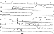
Третий формирователь импульсов 29 может быть реализован в виде двух формирователей импульсов (см. Справочник по интегральным микросхемам. ) Под ред. Б. В. Тарабрина. М. : Энергия, 1980, с. 668, рис. 5-141 и с. 667, рис. 5-139), выходы которых объединены по схеме ИЛИ, а на входы подаются сигналы с выходов второго формирователя импульсов 25 и второго счетчика 27 соответственно. Импульсы (см. фиг. 3 и 4, поз. 56), управляющие работой (сигнал запуска) первого и второго блоков выборки и хранения 17 и 18 (число импульсов, т. е. количество элементов в строке задается программно и может оперативно изменяться с клавиатуры) вырабатываются четвертым формирователем импульсов 31, на вход которого подаются импульсы с выхода второго счетчика 27. Не смотря на то, что четвертый формирователь импульсов 31 инициирует работу первого и второго блоков выборки и хранения 17 и 18 в течение всего периода сигнала, контроллер 22 выдает (выход 43) импульсы (см. фиг. 4, поз. 62) на второй вход блока привязки уровня 19 только с приходом второго (соответствует моменту попадания эталонного источника 10 в поле зрения) синхроимпульса (см. фиг. 4, поз. 50) с выхода датчика положения зеркала 6, а импульсы (см. фиг. 3 и 4, поз. 57), управляющие работой (сигнал запуска) первого и второго аналого-цифровых преобразователей 20 и 21 (выход 44), - только с приходом "четвертого" (соответствует началу строки) синхроимпульса (см. фиг. 4, поз. 50), для чего интервалы между ними (а они намеренно различны) измеряются с помощью специальной программы в контроллере 32. Интервалы между первым и вторым и между третьим и четвертым синхроимпульсами (см. фиг. 3, поз. 50) используются для измерения скорости вращения зеркала, т. е. производится подсчет числа импульсов тактовой частоты, уложившихся в этот интервал. The third pulse shaper 29 can be implemented in the form of two pulse shapers (see. Reference on integrated circuits.) Ed. B.V. Tarabrina. M.: Energy, 1980, p. 668, fig. 5-141 and p. 667, fig. 5-139), the outputs of which are combined according to the OR circuit, and the signals from the outputs of the second pulse shaper 25 and the second counter 27, respectively, are supplied to the inputs. Pulses (see Figs. 3 and 4, item 56) that control the operation (start signal) of the first and second sampling and
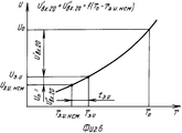
Измерение температуры То исследуемого объекта производится программно в контроллере 22 в соответствии с градуировочной кривой (см. фиг. 6), которая заложена в память контроллера 22. Здесь U-сигнал на выходе усилителя-преобразователя 13; Т - температура; То - температура объекта; Тэ. и. ном. - номинальная температура эталонного источника (начало отсчета по шкале температур); То. и. - текущая температура эталонного источника; t= э.и.= Тэ.и.ном.-Тэ. и. - нестабильность температуры Тэ. и. эталонного источника; Uо - сигнал на выходе усилителя-преобразователя при температуре исследуемого объекта То; Uэ.и. - сигнал на выходе усилителя-преобразователя 13 от эталонного источника при температуре Тэ.и., Uэ.и.ном. - сигнал на выходе усилителя-преобразователя 13 при номинальной температуре Тэ.и.ном. эталонного источника. При этом оцифрованные значения сигнала (выход первого аналого-цифрового преобразователя 20), схемная привязка которых к уровню сигнала от эталонного источника 10 выполняется в блоке привязки уровня 19, поступают на вход 40 контроллера 22, т. е. измерение температуры объекта осуществляется относительно температуры эталонного источника Тэ.и. Нестабильность температуры Т э.и. эталонного источника (уход от номинала на величину tэ.и.) вносит погрешность в измеряемую температуру объекта То из-за отличия сигнала (Uo-Uэ.и.), подлежащего оцифровке в первом аналого-цифровом преобразователе 20, от сигнала U'вх.20= (Uo-Uэ.и.ном.) на величину Uп= U''вх.20 (см. фиг. 6).The temperature T o of the test object is measured in software in the controller 22 in accordance with the calibration curve (see Fig. 6), which is stored in the memory of the controller 22. Here, the U-signal at the output of the amplifier-
В рассматриваемом устройстве компенсация температурной нестабильности эталонного источника 10 осуществляется следующим образом. In this device, the compensation of temperature instability of the
На входы модулятора 12 поступают сигнал Ut (в виде постоянного напряжения) с выхода датчика температуры 11 (см. Шило В. Л. Линейные интегральные схемы в радиоэлектронной аппаратуре. М. : Сов. радио 1979, с. 166, рис. 4.11, а. Здесь в мост включен терморезистор, находящийся в тепловом контакте с эталонным источником 10), пропорциональный уходу температуры эталонного источника 10 от номинала (последний соответствует нулю на входе первого аналого-цифрового преобразователя 20), и импульсы с выхода 48 контроллера 22 (см. фиг. 4, поз. 59), временно положение которых определяется синхроимпульсами (см. фиг. 4, поз. 50) с выхода датчика положения зеркала 6. Выходные импульсы модулятора 12 (фиг. 4, поз. 60), амплитуда которых равна Ut , а фаза определяется знаком Ut и синхроимпульсами, поступают на второй вход усилителя-преобразователя 13 (на вход смесителя 33), выходной сигнал которого показан на фиг. 4, поз. 61. Крутизна передаточной характеристики датчика температуры 11 выбирается равной крутизне характеристики, приведенной на фиг. 6. Модулятор 12 может быть реализован в виде управляемого коммутатора, на один вход которого поступает сигнал с выхода датчика температуры 11, другой вход заземлен, а на управляющий вход подаются импульсы с выхода 48 контроллера 22. В усилителе-преобразователе 13 сигналы с двух входов складываются, при этом напряжение (перепад) Utо (см. фиг. 4, поз. 61) пропорционально отклонению истиной температуры исследуемого объекта от номинальной температуры эталонного источника Тэ.и.ном. (см. фиг. 6), что означает компенсацию температурной нестабильности эталонного источника 10. В устройстве-прототипе сигнал термокомпенсации вводится после блока привязки уровня с помощью автономного компенсационного канала, имеющего в своем составе усилитель и сумматор, что приводит к появлению дополнительного смещения сигнала за счет погрешности, вносимой элементами самого компенсационного канала.The inputs of the modulator 12 receive a signal U t (in the form of a constant voltage) from the output of the temperature sensor 11 (see Shilo V.L. Linear integrated circuits in electronic equipment. M.: Sov. Radio 1979, p. 166, Fig. 4.11, A. Here, a thermistor is included in the bridge, which is in thermal contact with the reference source 10), proportional to the temperature of the
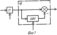
В блоке привязки уровня 19, упрощенная схема которого показана на фиг. 7, по импульсному сигналу с шестого выхода 43 котроллера 22 (фиг. 4, поз. 62) (временное положение определяется импульсами, изображенными на фиг. 4, поз. 56, поступающими на вход 45 контроллера 22, а длительность задается программно) запоминается уровень сигнала U1, соответствующий эталонному источнику 10, который вычитается при формировании отсчетов изображения. Введение блока привязки уровня 19 между первым блоком выборки и хранения (УВХ) 17 и первым аналого-цифровым преобразователем 20 приводит к тому, что погрешность смещения УВХ присутствует как в сигнале от объекта, так и в сигнале U1, соответствующем эталонному источнику 10. В результате вычитания этих сигналов в блоке привязки уровня 19 погрешность смещения УВХ устраняется.In the
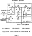
Контроллер 22 выполняет следующие функции: через третий 40 и четвертый 41 входы (первый и второй параллельные порты) воспринимает информацию с выходов первого и второго аналого-цифровых преобразователей 20 и 21, преобразует ее и выдает видеосигналы через видеовыход 42 на видеоконтрольный блок 32; через первый выход 44 (первый одноразрядный порт) выдает импульсы (см. фиг. 3 и 4, поз. 57), управляющие работой первого и второго аналого-цифровых преобразователей 20 и 21 (их временное положение определяется импульсами (см. фиг. 3 и 4, поз. 56), поступающими с выхода четвертого формирователя импульсов 31 на второй вход 45 (второй одноразрядный порт); через шестой выход 43 (третий одноразрядный порт) выдает импульсы (см. фиг. 4, поз. 62), управляющие работой блока привязки уровня; через пятый выход 48 (четвертый одноразрядный порт) выдает импульсы (см. фиг. 4, поз. 59), управляющие работой модулятора 12; через первый вход 46 (вход запроса прерываний, соединенный в контроллере 22 с пятым одноразрядным портом), воспринимает синхроимпульсы (см. фиг. 3 и 4, поз. 50) с выхода датчика положения зеркала 6 и измеряет временные интервалы между ними, классифицируя на "первый", "второй", "третий" и "четвертый" синхроимпульсы ("второй" синхроимпульс, соответствующий моменту попадания эталонного источника 10 в поле зрения, определяет момент выдачи импульсной последовательности на второй вход блока привязки уровня 19, "четвертый" синхроимпульс используется в качестве начала отсчета при формировании строки изображения); через четвертый выход 47 (третий параллельный порт) управляет работой управляемого делителя 30, записывая в него требуемый коэффициент деления; через третий выход 49 (четвертый параллельный порт) управляет шаговым приводом 8 (как показано в книге Т. Кенио. Шаговые двигатели и их микропроцессорные системы управления. М. : Энергоатомиздат, 1987, для управления шаговым приводом достаточно четырех управляющих сигналов, т. е. требуется четырехразрядный параллельный порт). При этом следует заметить, что одноразрядные порты могут быть однонаправленными (ввода или вывода). The controller 22 performs the following functions: through the third 40 and fourth 41 inputs (first and second parallel ports) it receives information from the outputs of the first and second analog-to-digital converters 20 and 21, converts it and provides video signals through video output 42 to the video control unit 32; through the first output 44 (the first one-bit port) it gives out pulses (see Figs. 3 and 4, item 57) that control the operation of the first and second analog-to-digital converters 20 and 21 (their temporary position is determined by the pulses (see Fig. 3 and 4, item 56) coming from the output of the fourth pulse shaper 31 to the second input 45 (second one-bit port); through the sixth output 43 (third one-bit port) it gives out pulses (see Fig. 4, pos. 62) that control the operation of the unit level bindings; through the fifth output 48 (the fourth one-bit port) it generates pulses (see Fig. 4, item 59 ), controlling the operation of the modulator 12; through the first input 46 (interrupt request input connected to the fifth single-bit port in the controller 22), it receives clock pulses (see Figs. 3 and 4, item 50) from the output of the mirror position sensor 6 and measures the time the intervals between them, classifying into “first”, “second”, “third” and “fourth” clock pulses (the “second” clock pulse corresponding to the moment the reference source 10 enters the field of view determines the moment the pulse sequence is issued to the second input of the level 19 blocking unit fourth the clock is used as a reference when forming the image line); through the fourth output 47 (third parallel port) controls the operation of the controlled divider 30, writing in it the required division ratio; through the third output 49 (the fourth parallel port) it controls the stepper drive 8 (as shown in the book by T. Kenio. Stepper motors and their microprocessor control systems. M.: Energoatomizdat, 1987, four control signals are sufficient to control the stepper drive, i.e. 4-bit parallel port required). It should be noted that single-bit ports can be unidirectional (input or output).
Сигналы видимого канала (выход первого аналого-цифрового преобразователя 20) и теплового канала (выход второго аналого-цифрового преобразователя 21) обрабатываются в контроллере 22 по специальной программе таким образом, что на его видеовыходе 42 формируются видеосигналы черно-белого изображения видимого диапазона и нормализованный видеосигнал теплового диапазона, который соответствует бинаризованному "тепловому портрету" объекта. Пороговое значение при бинаризации теплового изображения устанавливается оператором программно (с клавиатуры, входящей в состав контроллера 22). The signals of the visible channel (output of the first analog-to-digital converter 20) and the heat channel (output of the second analog-to-digital converter 21) are processed in the controller 22 according to a special program so that video signals of the black-and-white image of the visible range and a normalized video signal are generated on its video output 42 thermal range, which corresponds to the binarized "thermal portrait" of the object. The threshold value for binarization of the thermal image is set by the operator programmatically (from the keyboard included in the controller 22).
Контроллер 22 может быть реализован в виде какой-либо ЭВМ, имеющей видеовыход, вход запроса прерываний, четырех параллельных порта и пять одноразрядных (пятый одноразрядный порт соединен со входом запроса прерываний), в частности на основе управляющей ЭВМ типа IВМ РС, снабженной соответствующими платами расширения. В случае отсутствия ЭВМ с необходимой номенклатурой портов можно воспользоваться любой ЭВМ с открытой архитектурой, имеющей видеовыход (обеспечивает формирование цветного многоградационного изображения) и вход запроса прерываний, и дополнить ее соответствующим числом портов ввода-вывода путем включения их в общую шину (см. книгу Микропроцессоры. Кн. 1. Архитектура и проектирование микроЭВМ. Организация вычислительных процессов/Под ред. Л. Н. Преснухина. - М. : Высшая школа, 1986, с. 79, рис. 3.4, с. 186, рис. 7.13). Видеоконтрольный блок 32 представляет собой цветной телевизионный монитор, связанный с видеовыходом контроллера 22, на экране которого отображаются полученная смесь видимого и бинаризованного теплового изображений и температура в любой его точке кадра, выбираемой оператором с клавиатуры (клавиатура входит в состав контроллера 22). The controller 22 can be implemented in the form of any computer having a video output, an interrupt request input, four parallel ports and five single-bit ones (the fifth one-bit port is connected to the interrupt request input), in particular, based on a control computer of type IВМ PC equipped with corresponding expansion cards . In the absence of a computer with the necessary range of ports, you can use any computer with an open architecture that has a video output (provides the formation of a color multi-gradation image) and an interrupt request input, and supplement it with an appropriate number of input / output ports by including them in a common bus (see
На фиг. 2 представлена схема усилителя-преобразователя 13, состоящего из дифференциального усилителя 34, смесителя 33, усилителя обратной связи 35 и резистора 36. Неинвертирующий вход дифференциального усилителя 34 соединен с выходом первого фотоприемника 4, который может быть реализован на основе охлаждаемого терморезистора. Инвентирующий вход дифференциального усилителя 34 подключен к выходу смесителя 33. Резистор 36, включенный между выходом и инвертирующим входом дифференциального усилителя 34, обеспечивает отрицательную обратную связь и стабилизацию усиления. Необходимая для поддержания неизменной передаточной характеристики (см. фиг. 4) термостабилизация первого фотоприемника 4 в рассматриваемом устройстве осуществляется за счет параметрической обратной связи. Изменение температуры фотоприемника 4 приводит к возникновению сигнала на выходе дифференциального усилителя 34, который поступает через усилитель обратной связи 35 на термоэлектрический охладитель 14. В установившемся режиме (баланс сигналов, поступающих с одинаковым весом на инвертирующий и неинвертирующий входы дифференциального усилителя 34) использование общего источника питания Uсм для смесителя 33 и первого фотоприемника 4 позволяет одновременно обеспечить и нулевое проникновение пульсаций Uсм в сигнал.In FIG. 2 is a diagram of an amplifier-
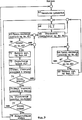
Схема программы, реализуемая контроллером 22, представлена на фиг. 9. Начальная установка (блок 63) включает в себя начальную установку счетчиков элементов в строке и строк в кадре, шагового привода, поля зрения, а также анализ интервалов между синхроимпульсами, поступающими на вход 36, путем программного опроса одноразрядного регистра ввода (в контроллере 22 вход запроса прерываний соединен с одноразрядным регистром ввода). В результате анализа интервалов контроллер 22 классифицирует синхроимпульсы на первый, второй, третий и четвертый и разрешает прерывание (блок 64) в интервале между первым и вторым синхроимпульсами. С приходом на вход 46 (вход запроса прерываний) второго синхроимпульса производится обработка прерывания (блок 65) и выполняется (блоки 66 и 67) программный анализ содержимого одноразрядного регистра (вход 45). При появлении сигнала на входе 45 контроллером 22 выдаются импульсы (выход 43) на второй вход блока привязки уровня 19, затем разрешается прерывание и выполняется переход к блоку 64. В дальнейшем обработка прерываний (блок 65) производится по приходу каждого синхроимпульса. При этом либо выполняется программа блока 66 (приход второго синхроимпульса), либо программа блока 69 (приход четвертого синхроимпульса), либо разрешается прерывание (блок 64), т. е. первый и третий синхроимпульсы пропускаются. Пропуск каждого первого и третьего синхроимпульса выполняется из-за того, что они используются только для формирования измерительного интервала при измерении скорости вращения зеркала. В случае прихода четвертого синхроимпульса (соответствует началу отсчета при формировании строки изображения), программный анализ содержимого одноразрядного регистра (вход 45) выполняется в блоках 69 и 70. При появлении сигнала на входе 45 контроллером 22 выдаются импульсы (выход 44) на первый и второй аналого-цифровые преобразователи (АЦП) 20 и 21 (блок 71), считываются и записываются в память (блок 72) коды с выходов первого и второго АЦП 20 и 21. Затем производится увеличение счетчика элементов в строке (блок 73) и проверка на конец строки (блок 74). Если строка не окончилась, выполняется переход к блоку 69. В противном случае обнуляется счетчик элементов в строке (блок 75), осуществляется перемещение зеркала на одну строку путем выдачи (блок 76) управляющих сигналов (выход 49) на шаговый привод 8 и производится проверка на конец кадра (блок 77). Если кадр не окончился, контроллер 22 входит в режим ожидания прерывания (блок 64), т. е. ждет прихода синхроимпульса на вход 46. По окончании кадра прерывания запрещаются, выполняется процедура бинаризации теплового изображения (блок 78) и на видеоконтрольный блок 32 выдается сигнал (выход 42), соответствующий смеси видимого и бинаризованного теплового изображений. Таким образом на экране видеоконтрольного блока 32 будет черно-белое изображение с окрашенными пятнами, соответствующими нагретым участкам анализируемого объекта, а также температура любой выбранной точки кадра. The program diagram implemented by the controller 22 is shown in FIG. 9. The initial installation (block 63) includes the initial installation of element counters in a row and rows in a frame, a step drive, a field of view, as well as an analysis of the intervals between clock pulses arriving at
Контроллер 22 формирует сигналы, поступающие на вход управления шагового привода 8, на вторые входы первого и второго аналого-цифровых преобразователей 20 и 21, что позволяет задавать программно число строк и число элементов изображения в строке (т. е. форматировать изображение), и на вход управления управляемого делителя 30, что обеспечивает возможность оперативного изменения поля зрения тепловизора. Введение первого блока выборки и хранения (УВХ) 17 перед блоком привязки уровня 19 (в прототипе УВХ - после блока привязки) позволяет избавиться от погрешности смещения УВХ. Это означает снижение требований к реализации самого УВХ, т. е. возможность его упрощения и удешевления. The controller 22 generates signals arriving at the control input of the
Итак, использование простого и дешевого оптико-механического тракта при структурных изменениях электронного тракта тепловизора без его усложнения (УВХ, место и форма введения компенсационного сигнала) и введении стабилизации растра в совокупности с возможностями задания числа элементов в строке и числа строк при визуализации изображения, а также управление полем зрения обеспечивают повышение точности измерения температуры и дополнительные удобства пользователя при улучшении визуального восприятия тепловой картины на фоне видимого изображения, что означает удешевление тепловизора и расширение его потребительских свойств при решении задач индикации нагретых частей объекта. Использование сигнала усилителя-преобразователя 13 для управления термоэлектрическим охладителем 14 позволяет обеспечить термостабилизацию первого фотоприемника 4, а следовательно, и стабилизацию передаточной характеристики тепловизора в целом достаточно простыми техническими средствами. Параллельно снижается проникновение пульсаций источника питания Uсм в сигнал. Это определяет преимущества предложенного устройства по сравнению с устройством-прототипом.So, the use of a simple and cheap optical-mechanical path for structural changes in the electronic path of the thermal imager without complicating it (UVX, the place and form of introducing the compensation signal) and introducing stabilization of the raster in conjunction with the ability to specify the number of elements in a row and the number of rows when rendering an image, and field of view control also provides improved temperature measurement accuracy and additional user comforts while improving the visual perception of the thermal picture against the background of the visible image, which means cheaper thermal imager and the expansion of its consumer properties in solving problems of indicating heated parts of the object. The use of the signal of the amplifier-
Claims (2)
Priority Applications (1)
| Application Number | Priority Date | Filing Date | Title |
|---|---|---|---|
| SU4906500 RU2012155C1 (en) | 1991-01-30 | 1991-01-30 | Thermal imager |
Applications Claiming Priority (1)
| Application Number | Priority Date | Filing Date | Title |
|---|---|---|---|
| SU4906500 RU2012155C1 (en) | 1991-01-30 | 1991-01-30 | Thermal imager |
Publications (1)
| Publication Number | Publication Date |
|---|---|
| RU2012155C1 true RU2012155C1 (en) | 1994-04-30 |
Family
ID=21557862
Family Applications (1)
| Application Number | Title | Priority Date | Filing Date |
|---|---|---|---|
| SU4906500 RU2012155C1 (en) | 1991-01-30 | 1991-01-30 | Thermal imager |
Country Status (1)
| Country | Link |
|---|---|
| RU (1) | RU2012155C1 (en) |
Cited By (6)
| Publication number | Priority date | Publication date | Assignee | Title |
|---|---|---|---|---|
| RU2137319C1 (en) * | 1998-03-30 | 1999-09-10 | Медведев Александр Владимирович | Compact heat-vision device |
| RU2199830C2 (en) * | 1999-08-24 | 2003-02-27 | Владимир Дмитриевич Бобрышев | Method and device for converting thermal image into electric signal |
| RU2214163C2 (en) * | 2001-06-27 | 2003-10-20 | Федеральное государственное унитарное предприятие "Московское конструкторское бюро "Электрон" | Method for carrying out software-assisted analysis of infrared component of human biological field |
| RU2297726C2 (en) * | 2002-06-25 | 2007-04-20 | Пекинский Научно-Технологический Университет | Insertion video complex for industrial furnaces and image processing system |
| RU2299522C1 (en) * | 2005-11-08 | 2007-05-20 | Федеральное государственное унитарное предприятие "Летно-исследовательский институт им. М.М. Громова" | Device for technical control in visible and infrared spectrum ranges |
| RU2575798C1 (en) * | 2014-12-30 | 2016-02-20 | Федеральное государственное автономное образовательное учреждение высшего образования "Национальный исследовательский Томский политехнический университет" | Thermal imaging system for external thermal imaging |
-
1991
- 1991-01-30 RU SU4906500 patent/RU2012155C1/en active
Cited By (6)
| Publication number | Priority date | Publication date | Assignee | Title |
|---|---|---|---|---|
| RU2137319C1 (en) * | 1998-03-30 | 1999-09-10 | Медведев Александр Владимирович | Compact heat-vision device |
| RU2199830C2 (en) * | 1999-08-24 | 2003-02-27 | Владимир Дмитриевич Бобрышев | Method and device for converting thermal image into electric signal |
| RU2214163C2 (en) * | 2001-06-27 | 2003-10-20 | Федеральное государственное унитарное предприятие "Московское конструкторское бюро "Электрон" | Method for carrying out software-assisted analysis of infrared component of human biological field |
| RU2297726C2 (en) * | 2002-06-25 | 2007-04-20 | Пекинский Научно-Технологический Университет | Insertion video complex for industrial furnaces and image processing system |
| RU2299522C1 (en) * | 2005-11-08 | 2007-05-20 | Федеральное государственное унитарное предприятие "Летно-исследовательский институт им. М.М. Громова" | Device for technical control in visible and infrared spectrum ranges |
| RU2575798C1 (en) * | 2014-12-30 | 2016-02-20 | Федеральное государственное автономное образовательное учреждение высшего образования "Национальный исследовательский Томский политехнический университет" | Thermal imaging system for external thermal imaging |
Similar Documents
| Publication | Publication Date | Title |
|---|---|---|
| US7237946B2 (en) | Use of IR camera | |
| US4639774A (en) | Moving target indication system | |
| US5252818A (en) | Method and apparatus for improved scanner accuracy using a linear sensor array | |
| JPH03132254A (en) | Proofreading device of color picture scanning and method therefor | |
| RU2012155C1 (en) | Thermal imager | |
| JPH03246428A (en) | Infrared video device | |
| US6355930B1 (en) | Fast infrared linear image optical instruments | |
| US6891162B2 (en) | Method of acquiring data from multi-element detector in infrared imaging apparatus | |
| US4652735A (en) | Image reader for X-ray film or the like having a detection system with an expanded dynamic range | |
| Gault et al. | Divided-mirror scanning technique for a small Michelson interferometer | |
| Küveler et al. | A matrix photodiode array to measure Doppler shifts of solar spectral lines | |
| US4181851A (en) | Automatic astroposition determination apparatus | |
| Gogler et al. | Fast and accurate polarimetric calibration of infrared imaging polarimetric sensors | |
| RU1814195C (en) | Infra-red imager | |
| RU1832403C (en) | Infra-red imager | |
| König et al. | Nonuniformity determination of infrared imagers by detecting radiance temperatures with the Data Reference Method | |
| Fraedrich | Methods in calibration and error analysis for infrared imaging radiometers | |
| JP2743427B2 (en) | Infrared imaging device | |
| RU2796192C1 (en) | Goniophotometric installation for measurement of parameters of lighting products and characteristics of radiation sources | |
| De La Barriere et al. | Instrumental development of NanoCarb, a new spectro-imaging sensor | |
| RU2299522C1 (en) | Device for technical control in visible and infrared spectrum ranges | |
| KR920001276B1 (en) | Projection resolution measuring device of the imaging optical system | |
| JPH0727610A (en) | Spectrophotometer | |
| Lenhard | Improving the calibration of airborne hyperspectral sensors for earth observation | |
| Krupiński et al. | Test stand for determining parameters of microbolometer camera |