RU2010503C1 - Milk recording device - Google Patents
Milk recording device Download PDFInfo
- Publication number
- RU2010503C1 RU2010503C1 SU4950526A RU2010503C1 RU 2010503 C1 RU2010503 C1 RU 2010503C1 SU 4950526 A SU4950526 A SU 4950526A RU 2010503 C1 RU2010503 C1 RU 2010503C1
- Authority
- RU
- Russia
- Prior art keywords
- milk
- air
- vacuum
- pipe
- electromagnetic valve
- Prior art date
Links
- 239000008267 milk Substances 0.000 title claims abstract description 35
- 235000013336 milk Nutrition 0.000 title claims abstract description 35
- 210000004080 milk Anatomy 0.000 title claims abstract description 35
- 238000004891 communication Methods 0.000 claims abstract description 8
- 239000012528 membrane Substances 0.000 claims abstract description 8
- 238000005265 energy consumption Methods 0.000 claims description 4
- 238000005192 partition Methods 0.000 claims description 3
- 238000004804 winding Methods 0.000 claims description 3
- 238000004458 analytical method Methods 0.000 claims 1
- 239000000126 substance Substances 0.000 abstract 1
- 238000010586 diagram Methods 0.000 description 2
- 239000002184 metal Substances 0.000 description 2
- 238000009825 accumulation Methods 0.000 description 1
- 230000015572 biosynthetic process Effects 0.000 description 1
- 239000004020 conductor Substances 0.000 description 1
- 238000003977 dairy farming Methods 0.000 description 1
- 244000144972 livestock Species 0.000 description 1
- 238000005259 measurement Methods 0.000 description 1
- 238000000034 method Methods 0.000 description 1
Images
Landscapes
- Measuring Fluid Pressure (AREA)
Abstract
Description
Изобретение относится к сельскому хозяйству, к молочному животноводству на промышленной основе, и может быть применено в системах учета количества молока на животноводческих фермах. The invention relates to agriculture, to dairy farming on an industrial basis, and can be applied in accounting systems for the amount of milk on livestock farms.
Известно устройство для учета количества молока, содержащее счетный блок, реле времени, цилиндрическую емкость с коническим основанием, разделенную конусной перегородкой на нижнюю мерную и верхнюю компенсационную камеры, электромагнитный клапан, обмотка которого подключена к цепи питания через контакты реле времени, к управляющему входу которого через усилитель подключены чувствительные элементы контактного датчика уровня. A device for recording the amount of milk containing a counting unit, a time relay, a cylindrical container with a conical base, divided by a conical partition into the lower measuring and upper compensation chambers, an electromagnetic valve, the winding of which is connected to the power circuit through the contacts of the time relay, to the control input of which amplifier connected to the sensitive elements of the contact level sensor.
Недостатком этого устройства является то, что при использовании электромагнитного клапана прямого действия для обеспечения усилий, необходимых для надежного закрытия клапана требуется большая мощность электромагнита, соответственно большой ток, что в свою очередь требует большого сечения проводов и большой мощности усилителя электрических сигналов. Указанные факторы существенно увеличивают расход электроэнергии и металлоемкость. Кроме того, наличие усилителя большой мощности усложняет конструкцию в целом. The disadvantage of this device is that when using a direct-acting solenoid valve, to ensure the forces necessary for reliable valve closure, a large power of the electromagnet is required, respectively, a large current, which in turn requires a large cross-section of wires and a large power of the electric signal amplifier. These factors significantly increase energy consumption and metal consumption. In addition, the presence of a high power amplifier complicates the design as a whole.
Целью изобретения является снижение энергоемкости и улучшение эксплуатационных параметров устройства. The aim of the invention is to reduce energy consumption and improve the operational parameters of the device.
Цель достигается тем, что в предлагаемом устройстве клапан закреплен на штоке воздушно-вакуумного усилителя, разделенного подпружиненной мембраной на молочную и воздушно-вакуумную полости, причем молочная полость сообщена с подводящим молочным патрубком, а воздушно-вакуумная полость имеет воздушный патрубок для соединения с полостью командным электромагнитным клапаном. The goal is achieved by the fact that in the proposed device, the valve is mounted on the rod of the air-vacuum amplifier, separated by a spring-loaded membrane into the milk and air-vacuum cavities, the milk cavity being in communication with the milk supply pipe, and the air-vacuum cavity has an air pipe for connection with the command cavity solenoid valve.
Замена в устройстве силового электромагнитного клапана прямого действия, потребляющего при срабатывании большой ток для обеспечения необходимого усилия на закрытие клапана, на маломощный командный электромагнитный клапан, управляющий работой воздушно-вакуумного усилителя, позволяет снизить расход энергии, существенно уменьшить металлоемкость. Использование усилителя малой мощности взамен усилителя большой мощности, потребного для работы электромагнитного клапана прямого действия, позволяет упростить конструкцию устройства. Сообщение молочной полости воздушно-вакуумного усилителя с подводящим молочным патрубком дает возможность использовать клапан для соединения молочного патрубка мерной камерой и разъединения их. Наличие воздушного патрубка, сообщающего воздушно-вакуумную полость усилителя с командным электромагнитным клапаном позволяет подавать в эту полость атмосферное давление, либо пониженное давление (вакуум). Командный электромагнитный клапан сообщает воздушно-вакуумную полость усилителя с вакуумпроводом или с атмосферой в соответствии с сигналами, поступающими от блока управления. Закрепление клапана на штоке воздушно-вакуумного усилителя позволяет осуществлять перемещение клапана из верхнего положения в нижнее, используя разницу сил нормального атмосферного давления и пониженного (вакуума), а из нижнего положения в верхнее, используя силу упругости пружины, тем самым открывая проход молоку, либо из подводящего патрубка в мерную камеру, либо из мерной - в сливной патрубок. Replacing a direct-acting power solenoid valve in the device, which, when activated, consumes a large current to provide the necessary force to close the valve, with a low-power command solenoid valve that controls the operation of the air-vacuum amplifier, can reduce energy consumption and significantly reduce metal consumption. The use of a low-power amplifier instead of a high-power amplifier, required for operation of a direct-acting solenoid valve, simplifies the design of the device. The communication of the milk cavity of the air-vacuum amplifier with the feeding milk pipe makes it possible to use a valve to connect the milk pipe with a measuring chamber and disconnect them. The presence of an air pipe that communicates the air-vacuum cavity of the amplifier with a command electromagnetic valve allows atmospheric pressure or a reduced pressure (vacuum) to be supplied to this cavity. The command solenoid valve communicates the air-vacuum cavity of the amplifier with a vacuum pipe or with the atmosphere in accordance with the signals received from the control unit. Fastening the valve to the rod of the air-vacuum amplifier allows the valve to be moved from the upper position to the lower one using the difference between normal atmospheric pressure and lowered (vacuum) forces, and from the lower position to the upper one, using the spring force, thereby opening the passage for milk, or from the supply pipe to the metering chamber, or from the metering pipe to the drain pipe.
Мембрана является основным силовым элементом воздушно-вакуумного усилителя, воспринимающим разность сил давления и передающим ее на шток. Пружина служит для возврата клапана в верхнее положение. The membrane is the main power element of the air-vacuum amplifier, perceiving the difference in pressure forces and transmitting it to the rod. The spring is used to return the valve to the upper position.
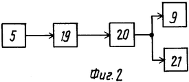
На фиг. 1 изображена конструктивная схема устройства; на фиг. 2 - блок-схема устройства. In FIG. 1 shows a structural diagram of a device; in FIG. 2 is a block diagram of a device.
Устройство для учета количества молока включает цилиндрический корпус, разделенный конусной перегородкой на нижнюю мерную 1 и верхнюю компенсационную 2 камеры, верхние части которых сообщены с воздушной трубкой 3. Вакуумная полость обеих камер соединена с отводящим патрубком 4 слива молока посредством воздушной трубки 3, с целью исключения возможности образования в них вакуумных пробок. Для обеспечения возможности работы устройства на передвижных установках при переменных углах наклона чувствительные элементы 5 контактного датчика уровня, измеряющие заданную порцию молока, устанавливают в перфорированном оголовке 6, имеющем ряд калибровочных отверстий 7 и расположенном на продольной оси цилиндрического корпуса мерной камеры 1 с коническим днищем. Чувствительные элементы 5 датчика уровня могут быть изготовлены из любого электропроводного материала, который допускается к использованию в молокопроводах. Перед началом работы чувствительные элементы 5 при настройке устройства устанавливаются на заданном расстоянии друг от друга. Это расстояние определяет заданный (измеряемый) объем молока в мерной камере 1. В процессе работы перемещение чувствительных элементов 5 не предусмотрено. Снаружи на управляющем воздушном патрубке 8 смонтирована обмотка командного электромагнитного клапана 9, в качестве которого можно использовать пневматический распределитель типа П-РЭ 3/1/5/, выходной штуцер которого сообщен с управляющим воздушным патрубком 8 усилителя, один из входных штуцеров сообщен с рабочим вакуумом, а второй - с атмосферой. The device for recording the amount of milk includes a cylindrical body, divided by a conical partition into the lower measuring 1 and upper compensation 2 chambers, the upper parts of which are in communication with the air tube 3. The vacuum cavity of both chambers is connected to the discharge pipe 4 of the milk drain through the air tube 3, in order to exclude the possibility of the formation of vacuum plugs in them. To enable the device to work on mobile units at variable angles of inclination, the
Клапан 10 закреплен на штоке 11 воздушно-вакуумного усилителя 12, разделенного подпружиненной мембраной 13 на молочную 14 и воздушно-вакуумную 15 полости. Молочная полость 14 сообщена с подводящим молочным патрубком 16, а воздушно-вакуумная полость 15 имеет воздушный патрубок 8 для соединения с командным электромагнитным клапаном 9. The valve 10 is mounted on the rod 11 of the air-vacuum amplifier 12, separated by a spring-loaded membrane 13 into a milk 14 and air-vacuum 15 cavity. The milk cavity 14 is in communication with the milk supply pipe 16, and the air-vacuum cavity 15 has an air pipe 8 for connection with a command electromagnetic valve 9.
Устройство работает следующим образом. The device operates as follows.
В начале доения обмотка командного электромагнитного клапана 9 обесточена, воздушно-вакуумная полость 15 усилителя 12 сообщается через воздушный патрубок 8 и командный электромагнитный клапан 9 с атмосферой, а молочная полость 14 сообщена с рабочим вакуумом, поэтому мембрана 13 под действием разности давлений прогибается вниз. Клапан 10 опускается в нижнее положение, перекрывает отводящий патрубок 4, молоко поступает в мерную камеру 1. Когда уровень молока достигает верхнего чувствительного элемента 5 датчика уровня, электрическая цепь замкнется, на обмотку командного электромагнитного клапана 9 будет подано напряжение, сердечник командного электромагнитного клапана 9 втянется и соединит воздушно-вакуумную полость 15 усилителя с рабочим вакуумом, при этом мембрана 13 под действием пружины 17 прогнется вверх, клапан 10 займет верхнее положение, перекроет входное отверстие в мерную камеру 1 и откроет выходное. Одновременно включается реле времени 19 через усилитель 20, замыкая цепь обмотки электромагнитного клапана 9 независимо от действия чувствительных элементов 5 датчиков уровня. Происходит опорожнение мерной камеры 1и заполнение компенсационной камеры 2. Через заданный промежуток времени, достаточный для опорожнения мерной камеры 1, реле времени 19 разомкнет свои контакты в цепи питания обмотки командного электромагнитного клапана 9, сердечник которого займет первоначальное положение. Воздушно-вакуумная полость 15 сообщается с атмосферой, мембрана 13 опускается вниз, клапаном 10 перекрывает отводящий патрубок 4, молоко из компенсационной камеры 2 будет поступать в мерную камеру 1. При замыкании молоком чувствительных элементов 5 процесс повторится и т. д. Сигналы от реле времени 19 подаются в счетчик импульсов счетного блока 21, который путем суммирования порций молока фиксирует общий надой при необходимости по времени накопления мерной камеры 1 определяет текущий расход (для подачи команды на додаивание и отключение доильного аппарата). At the beginning of milking, the coil of the command electromagnetic valve 9 is de-energized, the air-vacuum cavity 15 of the amplifier 12 communicates through the air pipe 8 and the command electromagnetic valve 9 with the atmosphere, and the milk cavity 14 is in communication with the working vacuum, so the membrane 13 bends down under the influence of the pressure difference. The valve 10 is lowered, closes the outlet pipe 4, the milk enters the measuring chamber 1. When the milk level reaches the
Перфорированный оголовок 6 с комбинированными отверстиями 7, в котором расположены чувствительные элементы 5 стабилизирует верхний уровень молока и предохраняет цепь от случайных срабатываний. Расположение оголовка 6 на оси мерной 1 камеры обеспечивает повышение точности замеров количества молока ввиду симметричности сечений цилиндрического корпуса последнего. (56) Авторское свидетельство СССР N 1699384, кл. А 01 J 7/00, 1989. A perforated head 6 with combined holes 7, in which the
Claims (1)
Priority Applications (1)
| Application Number | Priority Date | Filing Date | Title |
|---|---|---|---|
| SU4950526 RU2010503C1 (en) | 1991-06-26 | 1991-06-26 | Milk recording device |
Applications Claiming Priority (1)
| Application Number | Priority Date | Filing Date | Title |
|---|---|---|---|
| SU4950526 RU2010503C1 (en) | 1991-06-26 | 1991-06-26 | Milk recording device |
Publications (1)
| Publication Number | Publication Date |
|---|---|
| RU2010503C1 true RU2010503C1 (en) | 1994-04-15 |
Family
ID=21581939
Family Applications (1)
| Application Number | Title | Priority Date | Filing Date |
|---|---|---|---|
| SU4950526 RU2010503C1 (en) | 1991-06-26 | 1991-06-26 | Milk recording device |
Country Status (1)
| Country | Link |
|---|---|
| RU (1) | RU2010503C1 (en) |
Cited By (1)
| Publication number | Priority date | Publication date | Assignee | Title |
|---|---|---|---|---|
| RU2481767C2 (en) * | 2011-05-26 | 2013-05-20 | Российская академия сельскохозяйственных наук Государственное научное учреждение Всероссийский научно-исследовательский институт электрификации сельского хозяйства Российской академии сельскохозяйственных наук (ГНУ ВИЭСХ Россельхозакадемии) | Milk meter of vacuumised pipeline milking plant |
-
1991
- 1991-06-26 RU SU4950526 patent/RU2010503C1/en active
Cited By (1)
| Publication number | Priority date | Publication date | Assignee | Title |
|---|---|---|---|---|
| RU2481767C2 (en) * | 2011-05-26 | 2013-05-20 | Российская академия сельскохозяйственных наук Государственное научное учреждение Всероссийский научно-исследовательский институт электрификации сельского хозяйства Российской академии сельскохозяйственных наук (ГНУ ВИЭСХ Россельхозакадемии) | Milk meter of vacuumised pipeline milking plant |
Similar Documents
| Publication | Publication Date | Title |
|---|---|---|
| CA2399181A1 (en) | Fluid dispense and liquid surface verification system and method | |
| CZ219394A3 (en) | Method of taking samples of milk for analysis thereof in a proportional amount from a flow of milked milk and apparatus for making the same | |
| US4372249A (en) | Volumetric apparatus for milk and method of measuring the total quantity of milk collected from a cow in milking | |
| EP1022937A1 (en) | Intelligent claw | |
| RU2010503C1 (en) | Milk recording device | |
| US20190141942A1 (en) | Milking system and method | |
| US6497143B1 (en) | Container with automatically controlled discharge for continuous metering of liquid flow | |
| US4784193A (en) | Flowmeter | |
| JPH0668411B2 (en) | Automatic bath equipment | |
| GB1374774A (en) | Method of and apparatus for metering predetermined volumes of a liquid | |
| RU2048078C1 (en) | Device for measuring amount of milk | |
| KR100940941B1 (en) | Fixed flow rate supply device for applying sealer | |
| BG60042B2 (en) | Automatic milk counter in a milking machine | |
| RU2327343C1 (en) | Recording device of milk | |
| RU2081562C1 (en) | Milk indicator | |
| SU1727728A1 (en) | Device for control of condition of milking plant | |
| SU1722320A1 (en) | Method for machine milking | |
| RU93028504A (en) | MILK COUNTER | |
| JPH0138518Y2 (en) | ||
| US4947793A (en) | Method and means of determining milk yield from an animal | |
| SU1281906A1 (en) | Liquid metering device | |
| SU1435945A1 (en) | Method and apparatus for metering out liquid | |
| RU2264086C2 (en) | Milk counter | |
| SU1366122A1 (en) | Apparatus for checking technical condition of vacuum line | |
| HU203443B (en) | Milk-quantity measuring system for milking-machines particularly for individual milk-measuring |