RU200904U1 - ELECTRONIC MANUAL CONTACT WIRE WEAR METER - Google Patents
ELECTRONIC MANUAL CONTACT WIRE WEAR METER Download PDFInfo
- Publication number
- RU200904U1 RU200904U1 RU2020119604U RU2020119604U RU200904U1 RU 200904 U1 RU200904 U1 RU 200904U1 RU 2020119604 U RU2020119604 U RU 2020119604U RU 2020119604 U RU2020119604 U RU 2020119604U RU 200904 U1 RU200904 U1 RU 200904U1
- Authority
- RU
- Russia
- Prior art keywords
- measuring
- unit
- height
- gearbox
- roller
- Prior art date
Links
Images

Classifications
-
- B—PERFORMING OPERATIONS; TRANSPORTING
- B60—VEHICLES IN GENERAL
- B60M—POWER SUPPLY LINES, AND DEVICES ALONG RAILS, FOR ELECTRICALLY- PROPELLED VEHICLES
- B60M1/00—Power supply lines for contact with collector on vehicle
- B60M1/12—Trolley lines; Accessories therefor
-
- G—PHYSICS
- G01—MEASURING; TESTING
- G01B—MEASURING LENGTH, THICKNESS OR SIMILAR LINEAR DIMENSIONS; MEASURING ANGLES; MEASURING AREAS; MEASURING IRREGULARITIES OF SURFACES OR CONTOURS
- G01B7/00—Measuring arrangements characterised by the use of electric or magnetic techniques
Abstract
Предложенная полезная модель относится к области контроля состояния проводной контактной сети электрифицированных железных дорог, и более конкретно, к ручным приборам, предназначенным для измерения остаточной высоты и износа контактных проводов (КП) электрифицированных железных дорог и городского электротранспорта. Измеритель износа контактного провода ручной электронный содержит первый опорный ролик, второй опорный ролик, блок питания, пульт управления, электронный блок и измерительный блок, включающий в себя блок измерения высоты КП и дополнительный блок измерения высоты КП. Блок питания соединён с пультом управления, измерительным блоком и электронным блоком, электронный блок соединён с пультом управления и измерительным блоком. Блок измерения высоты КП и дополнительный блок измерения высоты КП расположены в концевых частях измерителя. Блок измерения высоты контактного провода включает в себя измерительный ролик, дополнительный блок измерения высоты контактного провода включает в себя измерительный ролик, при этом ось первого опорного ролика и ось измерительного ролика блока измерения высоты контактного провода расположены на одной линии, перпендикулярной продольной оси измерителя износа контактного провода ручного электронного, а ось второго опорного ролика и ось измерительного ролика дополнительного блока измерения высоты контактного провода расположены на одной линии, перпендикулярной оси измерителя износа контактного провода ручного электронного. Технический результат заключается в уменьшении нагрузки на пользователя при использовании измерителя износа КП ручного электронного, в частности, при проведении измерения износа КП посредством измерителя износа КП ручного электронного. 7 з.п. ф-лы, 9 ил.The proposed utility model relates to the field of monitoring the state of the wire contact network of electrified railways, and more specifically, to hand-held devices designed to measure the residual height and wear of contact wires (CP) of electrified railways and urban electric transport. The handheld electronic contact wire wear meter contains a first support roller, a second support roller, a power supply, a control panel, an electronic unit and a measuring unit, which includes a gearbox height measurement unit and an additional gearbox height measurement unit. The power supply is connected to the control panel, the measuring unit and the electronic unit, the electronic unit is connected to the control panel and the measuring unit. The block for measuring the height of the gearbox and the additional block for measuring the height of the gearbox are located in the end parts of the meter. The unit for measuring the height of the overhead wire includes a measuring roller, an additional unit for measuring the height of the overhead wire includes a measuring roller, while the axis of the first support roller and the axis of the measuring roller of the unit for measuring the height of the overhead wire are located on the same line perpendicular to the longitudinal axis of the trolley wire wear meter handheld electronic, and the axis of the second support roller and the axis of the measuring roller of the additional unit for measuring the height of the contact wire are located on the same line perpendicular to the axis of the handheld electronic contact wire wear meter. The technical result consists in reducing the load on the user when using a hand-held electronic gearbox wear meter, in particular, when measuring gearbox wear by means of a hand-held electronic gearbox wear meter. 7 p.p. f-ly, 9 ill.
Description
Область техники, к которой относится полезная модельThe technical field to which the utility model belongs
[0001] Предложенная полезная модель относится к области контроля состояния проводной контактной сети (далее – КС) электрифицированных железных дорог, и более конкретно, к ручным приборам, предназначенным для измерения остаточной высоты и износа контактных проводов (далее – КП) электрифицированных железных дорог и городского электротранспорта.[0001] The proposed utility model relates to the field of monitoring the state of a wired contact network (hereinafter - CC) of electrified railways, and more specifically, to hand-held devices designed to measure the residual height and wear of contact wires (hereinafter - CP) of electrified railways and urban electric transport.
Уровень техникиState of the art
[0002] Для обеспечения безотказного функционирования сети железных дорог и городского электротранспорта необходимо постоянно контролировать рабочее состояние проводной контактной сети для детектирования отклонений от номинальных значений оцениваемых параметров контактной сети, что позволит своевременно спланировать и произвести необходимые работы по ремонту или замене износившихся или повреждённых участков контактной сети.[0002] To ensure the trouble-free operation of the railway network and urban electric transport, it is necessary to constantly monitor the operating condition of the wired contact network to detect deviations from the nominal values of the estimated parameters of the contact network, which will allow timely planning and performing the necessary work to repair or replace worn out or damaged sections of the contact network ...
[0003] В отличие от других устройств электроснабжения контактная сеть не имеет резерва, поэтому к её надёжности предъявляют повышенные требования, которые учитываются как при проектировании и монтаже КС, так и при осуществлении последующего её технического обслуживания и ремонта. В частности, необходимо регулярно выполнять оценку состояния КС, для чего, как правило, используются вагоны-лаборатории, оснащённые средствами технической диагностики. Особенно это касается токоподводящего КП, чрезмерный износ которого может привести к его обрыву с непредсказуемыми последствиями, т.к. КП является единственным проводом КС, осуществляющим непосредственный контакт с токоприёмниками (пантографами) электроподвижного состава в процессе токосъёма. Поэтому целью диагностики контактной сети обычно в первую очередь является оценка состояния КП.[0003] Unlike other power supply devices, the contact network does not have a reserve, therefore, increased requirements are imposed on its reliability, which are taken into account both in the design and installation of the compressor station, and in the implementation of its subsequent maintenance and repair. In particular, it is necessary to regularly assess the state of the compressor station, for which, as a rule, laboratory cars equipped with technical diagnostics are used. This is especially true of the current-supplying gearbox, the excessive wear of which can lead to its breakage with unpredictable consequences, because The gearbox is the only wire of the compressor station that makes direct contact with the pantographs of the electric rolling stock during the current collection process. Therefore, the purpose of diagnostics of the contact network is usually first of all to assess the state of the gearbox.
[0004] Однако автоматизированные средства оценки состояния КП лишь фиксируют имеющиеся дефекты КП и не дают точной количественной оценки износа КП. Кроме того, упомянутые автоматизированные средства оценки состояния КП используются, в основном, на магистральных железнодорожных путях. На второстепенных участках железнодорожного сообщения, таких как незначительные по протяжённости боковые пути, тупиковые участки пути, пути на конечных привокзальных территориях, пути сортировочных станций, подъездные пути в промышленных зонах и т.п., а также при контроле КС городского электротранспорта используется визуальный метод оценки состояния КС, сопровождающийся последующим измерением износа КП ручным способом, описанным ниже.[0004] However, automated means for assessing the condition of the gearbox only record the existing defects of the gearbox and do not provide an accurate quantitative estimate of the gearbox wear. In addition, the above-mentioned automated means for assessing the state of the checkpoint are used mainly on main railway tracks. On secondary sections of railway communication, such as insignificant side tracks, dead-end sections of the track, tracks at the terminal landside areas, tracks of marshalling yards, access roads in industrial zones, etc., as well as when controlling the compressor station of urban electric transport, a visual assessment method is used the state of the gearbox, accompanied by the subsequent measurement of gearbox wear by the manual method described below.
[0005] После обнаружения дефектов КП на это место высылается бригада обслуживания КС, в составе которой имеются два оператора, осуществляющие замеры повреждённого участка КП ручным способом. Один оператор поднимается на железнодорожный лейтер (передвижную по рельсам железнодорожного пути съёмную изолирующую вышку) или на механизированную вышку, измеряет размеры изношенного участка КП с помощью ручных средств измерения, таких как штангенциркуль, микрометр, ультразвуковые высотомеры и т.п., и сообщает голосовым способом результаты измерений второму оператору, находящемуся на земле. Последний фиксирует полученные результаты измерений, а также местоположение точки измерения по её отстоянию от ближайшей опоры контактной сети. В дальнейшем данные о повреждённом участке КС передаются в ремонтную службу, где анализируются и, в случае необходимости, высылается ремонтная бригада для замены дефектного участка КП.[0005] After the detection of defects in the control panel, a CS maintenance team is sent to this place, which includes two operators who measure the damaged section of the control panel manually. One operator climbs onto a railway leiter (removable insulating tower movable along the rails of a railway track) or a mechanized tower, measures the size of the worn-out section of the gearbox using manual measuring instruments such as a vernier caliper, micrometer, ultrasonic altimeters, etc., and reports by voice measurement results to the second operator on the ground. The latter records the obtained measurement results, as well as the location of the measurement point by its distance from the nearest overhead support. In the future, data on the damaged section of the gearbox is transferred to the repair service, where it is analyzed and, if necessary, a repair team is sent to replace the defective section of the gearbox.
[0006] Однако подобный способ измерения величины износа КП с использованием ручных инструментов и приборов обладает рядом существенных недостатков.[0006] However, this method of measuring the amount of wear of the KP using hand tools and devices has a number of significant drawbacks.
[0007] Во-первых, при использовании ручного измерительного инструмента даже в электронном исполнении для получения высокой точности измерения необходимо, чтобы ручной измерительный инструмент располагался строго перпендикулярно продольной оси КП, что трудно обеспечить в ручном режиме, поскольку одной рукой надо удерживать измерительный инструмент, а второй рукой вращать ручку перемещения подвижного штока микрометра или прижимать измерительную головку ультразвукового высотометра к КП, и при этом считывать показания Измерителя.[0007] Firstly, when using a hand-held measuring tool, even in electronic design, to obtain high measurement accuracy, it is necessary that the hand-held measuring tool is located strictly perpendicular to the longitudinal axis of the gearbox, which is difficult to ensure in manual mode, since one hand must hold the measuring tool, and with the other hand, rotate the handle of moving the micrometer rod or press the measuring head of the ultrasonic altimeter to the gearbox, and at the same time read the readings of the Meter.
[0008] Во-вторых, при необходимости провести измерения на протяжённом участке КП в нескольких точках необходимо повторять данную операцию в каждой точке измерения, что увеличивает требуемое время проведения измерений.[0008] Secondly, if it is necessary to carry out measurements on an extended section of the CP at several points, it is necessary to repeat this operation at each measurement point, which increases the required measurement time.
[0009] В-третьих, при голосовой передаче результатов измерения одним оператором другому могут возникать ошибки, обусловленные человеческим фактором, а именно, ошибками восприятия информации «на слух», и как следствие, искажение или потеря части результатов проведённых измерений.[0009] Thirdly, during voice transmission of measurement results from one operator to another, errors may occur due to a human factor, namely, errors in the perception of information "by ear", and as a result, distortion or loss of part of the results of the measurements.
[0010] В-четвертых, привязка точки измерения к местности (определение расстояния до ближайшей опоры контактной сети) также не точна, поскольку осуществляется «на глазок».[0010] Fourth, the binding of the measurement point to the terrain (determining the distance to the nearest support of the contact network) is also not accurate, since it is carried out "by eye".
[0011] В-пятых, на зрительную фиксацию результатов измерения существенное влияние оказывают погодные условия, в первую очередь, яркое слепящее солнце или, наоборот, сумерки, а также дождь, снег, сильный ветер.[0011] Fifth, the visual fixation of measurement results is significantly influenced by weather conditions, first of all, a bright blinding sun or, conversely, twilight, as well as rain, snow, strong wind.
[0012] Известен измеритель износа КП ручной электронный, раскрытый в выпускной квалификационной работе бакалавра по теме «Носимый измеритель износа КП» студента Захарова Д. В., опубл. 2016 г. Известное техническое решение содержит корпус с рукояткой, блок питания, измерительный блок, электронный блок и пульт управления. измерительный блок включает в себя блок измерения высоты КП и блок измерения перемещения измерителя вдоль КП. Пульт управления содержит блок органов управления, выполненный в виде трёх кнопок, и дисплей. Электронный блок выполнен с возможностью сбора, обработки и передачи данных во внешние устройства и содержит аналогово-цифровой преобразователь (далее – АЦП), фильтр нижних частот, необходимый для снижения уровня низкочастотных помех, микроконтроллер и блок связи для передачи данных во внешние устройства, выполненный в виде модуля Bluetooth. Блок измерения высоты КП выполнен в виде потенциометрического датчика линейного перемещения и содержит прижимной элемент и чувствительный элемент. Блок измерения перемещения выполнен на основе оптического датчика линейного перемещения, содержащего светодиодный излучатель с линзой, фотодиодный приёмник с компараторами и оптический трафарет. Электронный блок соединён с блоком питания, блоком измерения высоты КП, блоком измерения перемещения. Блок питания соединён с пультом управления, блоком измерения высоты КП и блоком измерения перемещения.[0012] Known hand-held electronic KP wear meter, disclosed in the final qualifying work of a bachelor on the topic "Wearable KP wear meter" student DV Zakharov, publ. 2016 A well-known technical solution contains a housing with a handle, a power supply, a measuring unit, an electronic unit and a control panel. the measuring unit includes a block for measuring the height of the gearbox and a unit for measuring the displacement of the meter along the gearbox. The control panel contains a block of controls, made in the form of three buttons, and a display. The electronic unit is configured to collect, process and transmit data to external devices and contains an analog-to-digital converter (hereinafter referred to as ADC), a low-pass filter necessary to reduce the level of low-frequency interference, a microcontroller and a communication unit for transmitting data to external devices, made in the form of a Bluetooth module. The unit for measuring the height of the gearbox is made in the form of a potentiometric linear displacement transducer and contains a clamping element and a sensitive element. The displacement measuring unit is made on the basis of an optical linear displacement transducer containing an LED emitter with a lens, a photodiode receiver with comparators and an optical stencil. The electronic unit is connected to the power supply unit, the gearbox height measurement unit, and the displacement measurement unit. The power supply is connected to the control panel, the gearbox height measurement unit and the displacement measurement unit.
[0013] Известное техническое решение обладает недостатками:[0013] The known technical solution has disadvantages:
[0014] 1. Использование потенциометрического датчика линейного перемещения обуславливает значительный вес и габариты прибора, что может вызвать неудобство его использования, поскольку необходимо его многократно поднимать и опускать.[0014] 1. The use of a potentiometric linear displacement transducer causes significant weight and dimensions of the device, which can cause inconvenience in its use, since it is necessary to repeatedly raise and lower it.
[0015] 2. Блок измерения перемещения выполнен на основе оптического датчика линейного перемещения, содержащего светодиодный излучатель с линзой, фотодиодный приёмник с компараторами и оптический трафарет, закрепляемый на одной оси с измерительным роликом прибора. Использования оптического датчика линейного перемещения усложняет конструкцию и уменьшает технологичность прибора.[0015] 2. The displacement measuring unit is made on the basis of an optical linear displacement transducer containing an LED emitter with a lens, a photodiode receiver with comparators and an optical stencil fixed on the same axis with the measuring roller of the device. The use of an optical linear displacement transducer complicates the design and reduces the manufacturability of the device.
[0016] 3. Использование дополнительного оборудования, которое также усложняет конструкцию и уменьшает технологичность прибора. Такими устройствами, в частности, являются:[0016] 3. The use of additional equipment, which also complicates the design and reduces the manufacturability of the device. Such devices are, in particular:
[0017] - фильтр нижних частот, выполненного на операционном усилителе (ОУ), для подавления наводки от КП промышленной частоты 50 Гц,[0017] - a low-pass filter, made on an operational amplifier (OA), to suppress pickup from the QP power frequency 50 Hz,
[0018] - АЦП.[0018] - ADC.
[0019] 4. Высокая стоимость компонентов, в частности, потенциометрического датчика линейного перемещения и оптического датчика линейного перемещения.[0019] 4. The high cost of components, in particular the potentiometric linear encoder and the optical linear encoder.
[0020] 5. В электронном блоке не реализована возможность непосредственного вычисления износа КП. Для вычисления износа КП требуется дополнительное оборудования для проведения расчётов.[0020] 5. The electronic unit does not implement the ability to directly calculate the gearbox wear. To calculate gearbox wear, additional equipment is required to carry out the calculations.
[0021] Известны измерители износа КП ручные электронные автоматизированные, раскрытые в патенте России № 194125 на полезную модель, опубл. 28.11.2019 г., патенте России № 195428 на полезную модель, опубл. 28.01.2020 г., и в патенте России № 195537, опубл. 30.01.2020 г.[0021] Known hand-held electronic automated KP wear gauges disclosed in Russian patent No. 194125 for utility model, publ. November 28, 2019, Russian patent No. 195428 for a useful model, publ. January 28, 2020, and in the Russian patent No. 195537, publ. January 30, 2020
[0022] Известные технические решения 1 автоматизированных ручных электронных измерителей износа КП (далее – известные измерители 1) содержат корпус, снабжённый рукояткой, первый опорный ролик 2, второй опорный ролик 3, блок питания, пульт управления, измерительный блок и электронный блок. Блок питания соединён с пультом управления, измерительным блоком и электронным блоком. Пульт управления содержит блок органов управления, выполненный в виде трёх кнопок, и блок индикации, выполненные в виде дисплея. Электронный блок соединён с пультом управления и измерительным блоком и содержит блок обработки и хранения информации, выполненный с возможностью вычисления износа КП и сохранения результатов вычисления износа КП, и блок связи, корпус которого выполнен из радиопрозрачного материала. Измерительный блок включает в себя блок измерения высоты КП и блок измерения перемещения вдоль КП. Блок измерения высоты КП содержит измерительный ролик 4, закреплённый на подвижном прижимном рычаге, магнитную измерительную ленту и магнитную считывающую головку. Блок измерения перемещения содержит измерительный ролик, закреплённый на корпусе, магнитную измерительную ленту и магнитную считывающую головку.[0022] Known
[0023] Известные измерители 1 обладают следующими недостатками.[0023]
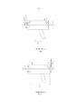
[0024] 1. Повышенная трудозатратность при эксплуатации известных измерителей 1 и, как следствие, снижение производительности труда пользователя (оператора). Указанный недостаток подробно пояснён на чертежах, поясняющих примерный способ измерения износа КП 5 вблизи струнового зажима 6 поддерживающей струны 7 КП 5. На первом этапе, представленном на Фиг. 1, помещают известный измеритель 1 на КП 5 и перемещают его вдоль КП 5 в прямом направлении 8 до соприкосновения со струновым зажимом 6. Со ссылкой на Фиг. 2, если после завершения первого этапа снять известный измеритель 1 с КП 5, разместить его после струнового зажима 6 вплотную к нему, сохранив при этом его ориентацию, т.е. ту ориентацию, что была на первом этапе, то в этой ситуации измерительный ролик 4 будет отступать на некоторое расстоянии от струнового зажима 6, а КП 5 будет содержать участок 9 отступа, ограниченный с одной стороны измерительным роликом 4, а с другой – струновым зажимом 6. Длина участка 9 отступа соответствует расстоянию между измерительным роликом 4 и струновым зажимом 6, которое может, например, составлять не менее длины известного измерителя 1. При дальнейшем проведении исследования КП 5 в прямом направлении 8 участок 9 отступа КП 5 не будет исследован. Для избежания такой ситуации, когда некоторые участки КП 5 не исследованы, на втором этапе, представленном на Фиг. 3 выполняют отдельное исследование участка 9 отступа. Для этого снимают известный измеритель 1 с КП 5, изменяют его пространственную ориентацию посредством разворота на 180 градусов в горизонтальной плоскости и помещают за струновым зажимом 6 на расстояние, составляющее не менее длины участка 9 отступа. На третьем этапе перемещают известный измеритель 1 вдоль КП 5 в обратном направлении 10 до момента соприкосновения со струновым зажимом 6 (см. Фиг. 4, осуществляя таким образом измерения износа КП 5 на участке 9 отступа. Со ссылкой на Фиг. 2, на четвёртом этапе снимают известный измеритель 1 с КП 5, разворачивают на 180 градусов в горизонтальной плоскости и помещают на КП 5 за струновый зажим 6 и вплотную к нему. На четвёртом этапе продолжают исследование КП 5 в прямом направлении 8 до соприкосновения со следующим струновым зажимом 6. В результате необходим дополнительный этапе измерения участка 9 отступа.[0024] 1. Increased labor costs during the operation of the known
[0025] 2. В процессе измерения оператор должен постоянно удерживать известный измеритель 1 в положении плотного прижатия его к КП 5. В противном случае при перемещении известного измерителя 1 возможен его наклон вперёд по направлению перемещения, при котором второй опорный ролик 3 известного измерителя 1 и соосный с ним измерительный ролик 4 блока измерения перемещения известного измерителя 1 приподнимаются над КП 5 и перестают вращаться при перемещении известного измерителя 1. Это приводит, во-первых, к неработоспособности блока измерения перемещения известного измерителя 1, а во-вторых, к неправильному измерению высоты КП 5, так как при наклоне известного измерителя 1 вперёд линия измерения высоты КП 5, проходящая через центры первого опорного ролика 2 и измерительного ролика 4 блока измерения высоты КП отклоняется от перпендикуляра к КП 5. Измеренная в этом случае высота КП 5 будет больше истинного её размера и, следовательно, рассчитанный износ КП 5 будет меньше его реального износа, что недопустимо.[0025] 2. During the measurement, the operator must constantly hold the known
[0026] Техническая проблема заключается в создании измерителя износа КП ручного электронного, в котором устранены описанные выше недостатки, в частности использование которого позволяет упростить процесс измерения износа КП, повысить эргономичность.[0026] The technical problem is to create a hand-held electronic gearbox wear meter, which eliminates the above-described disadvantages, in particular, the use of which makes it possible to simplify the process of measuring gearbox wear and improve ergonomics.
Раскрытие полезной моделиDisclosure of a utility model
[0027] Технический результат заключается в уменьшении нагрузки на пользователя при использовании измерителя износа КП ручного электронного, в частности, при проведении измерения износа КП посредством измерителя износа КП ручного электронного.[0027] The technical result consists in reducing the load on the user when using a manual electronic gearbox wear meter, in particular, when measuring gearbox wear using a handheld electronic gearbox wear meter.
[0028] Технический результат достигается за счёт того, что измеритель износа контактного провода ручной электронный содержит первый опорный ролик, второй опорный ролик, блок питания, пульт управления, электронный блок и измерительный блок, включающий в себя блок измерения высоты КП и дополнительный блок измерения высоты КП, при этом блок питания соединён с пультом управления, измерительным блоком и электронным блоком, электронный блок соединён с пультом управления и измерительным блоком, блок измерения высоты КП и дополнительный блок измерения высоты КП расположены в концевых частях измерителя, блок измерения высоты контактного провода включает в себя измерительный ролик, дополнительный блок измерения высоты контактного провода включает в себя измерительный ролик, при этом ось первого опорного ролика и ось измерительного ролика блока измерения высоты контактного провода расположены на одной линии, перпендикулярной продольной оси измерителя износа контактного провода ручного электронного, а ось второго опорного ролика и ось измерительного ролика дополнительного блока измерения высоты контактного провода расположены на одной линии, перпендикулярной оси измерителя износа контактного провода ручного электронного.[0028] The technical result is achieved due to the fact that a hand-held electronic trolley wire wear meter contains a first support roller, a second support roller, a power supply, a control panel, an electronic unit and a measuring unit including a gearbox height measurement unit and an additional height measurement unit The gearbox, while the power supply is connected to the control panel, the measuring unit and the electronic unit, the electronic unit is connected to the control panel and the measuring unit, the gearbox height measurement unit and the additional gearbox height measurement unit are located in the end parts of the meter, the contact wire height measurement unit includes itself a measuring roller, an additional unit for measuring the height of the contact wire includes a measuring roller, while the axis of the first support roller and the axis of the measuring roller of the unit for measuring the height of the contact wire are located on the same line, perpendicular to the longitudinal axis of the wear gauge of the contact wire of the manual electronic o, and the axis of the second support roller and the axis of the measuring roller of the additional unit for measuring the height of the contact wire are located on the same line perpendicular to the axis of the handheld electronic contact wire wear meter.
[0029] В дополнительном аспекте предложенное техническое решение характеризуется тем, что блок измерения высоты контактного провода содержит магнитную измерительную ленту и магнитную считывающую головку, дополнительный блок измерения высоты контактного провода содержит магнитную измерительную ленту и магнитную считывающую головку.[0029] In a further aspect, the proposed technical solution is characterized in that the overhead wire height measuring unit comprises a magnetic measuring tape and a magnetic read head, the additional overhead wire height measuring unit comprises a magnetic measuring tape and a magnetic reading head.
[0030] В дополнительном аспекте предложенное техническое решение характеризуется тем, что оно выполнено с возможностью измерения высоты контактного провода в двух режимах работы, при этом в одном режиме он выполнен с возможностью измерения высоты контактного провода посредством одного из блоков измерения высоты контактного провода, а в другом режиме он выполнен с возможностью измерения высоты контактного провода посредством блока измерения высоты контактного провода и дополнительного блока измерения высоты контактного провода.[0030] In an additional aspect, the proposed technical solution is characterized in that it is configured to measure the height of the overhead wire in two modes of operation, while in one mode it is configured to measure the height of the overhead wire using one of the blocks for measuring the height of the overhead wire, and in another mode, it is configured to measure the height of the overhead wire by means of a unit for measuring the height of the overhead wire and an additional unit for measuring the height of the overhead wire.
[0031] В дополнительном аспекте предложенное техническое решение характеризуется тем, что пульт управления содержит блок индикации.[0031] In a further aspect, the proposed technical solution is characterized in that the control panel comprises an indication unit.
[0032] В дополнительном аспекте предложенное техническое решение характеризуется тем, что блок индикации содержит дисплей.[0032] In a further aspect, the proposed technical solution is characterized in that the display unit comprises a display.
[0033] В дополнительном аспекте предложенное техническое решение характеризуется тем, что электронный блок включает в себя блок обработки и хранения информации, выполненный с возможностью расчёта износа контактного провода и сохранения результатов износа контактного провода.[0033] In an additional aspect, the proposed technical solution is characterized in that the electronic unit includes an information processing and storage unit configured to calculate the wear of the overhead wire and store the results of the wear of the overhead wire.
[0034] В дополнительном аспекте предложенное техническое решение характеризуется тем, что измерительный блок содержит блок измерения перемещения.[0034] In a further aspect, the proposed technical solution is characterized in that the measuring unit comprises a movement measuring unit.
[0035] В дополнительном аспекте предложенное техническое решение характеризуется тем, что электронный блок включает в себя блок связи, выполненный с возможностью передачи данных во внешнее устройство посредством беспроводного канала связи.[0035] In a further aspect, the proposed technical solution is characterized in that the electronic unit includes a communication unit configured to transmit data to an external device via a wireless communication channel.
Краткое описание чертежей Brief Description of Drawings
[0036] На Фиг. 1 представлена ориентация известного из уровня техники устройства при выполнении измерения в прямом направлении при приближении к струновому зажиму.[0036] FIG. 1 shows the orientation of the prior art device when measuring in the forward direction when approaching a string clamp.
[0037] На Фиг. 2 представлена ориентация известного из уровня техники устройства при выполнении измерения в прямом направлении после струнового зажима. [0037] FIG. 2 shows the orientation of the prior art device when measuring in the forward direction after a string clamp.
[0038] На Фиг. 3 представлена ориентация известного из уровня техники устройства при выполнении измерения в обратном направлении при приближении к струновому зажиму.[0038] FIG. 3 shows the orientation of the prior art device when measuring in the reverse direction when approaching the string clamp.
[0039] На Фиг. 4 представлена ориентация известного из уровня техники устройства, приведённого в контакт со струновым зажимом, при выполнении измерения в обратном направлении.[0039] FIG. 4 shows the orientation of a prior art device brought into contact with a string clip when measured in the opposite direction.
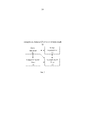
[0040] На Фиг. 5 представлена структурная схема варианта выполнения предложенного технического решения.[0040] FIG. 5 shows a block diagram of an embodiment of the proposed technical solution.
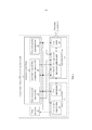
[0041] На Фиг. 6 представлена функциональная схема варианта выполнения предложенного технического решения.[0041] FIG. 6 shows a functional diagram of an embodiment of the proposed technical solution.
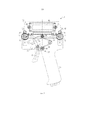
[0042] На Фиг. 7 представлено конструктивное исполнение варианта выполнения предложенного технического решения.[0042] FIG. 7 shows the design of an embodiment of the proposed technical solution.
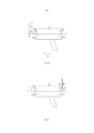
[0043] На Фиг. 8 представлено размещение варианта выполнения на КП при проведении измерения до струнового зажима.[0043] FIG. 8 shows the placement of the embodiment on the gearbox during the measurement before the string clamp.
[0044] На Фиг. 9 представлено размещение варианта выполнения на КП при проведении измерения после струнового зажима.[0044] FIG. 9 shows the placement of the embodiment on the gearbox during the measurement after the string clamp.
Осуществление полезной моделиImplementation of the utility model
[0045] На Фиг. 5 представлена общая схема структурная схема варианта выполнения измерителя 11 износа КП ручного электронного (далее – Измеритель 11). Измеритель 11 содержит блок 12 питания, пульт 13 управления, измерительный блок 14 и электронный блок 15. Блок 12 питания соединён с пультом 13 управления, измерительным блоком 14 и электронным блоком 15. Электронный блок 15 соединён с пультом 13 управления и измерительным блоком 14.[0045] FIG. 5 shows a general diagram of a block diagram of an embodiment of a handheld electronic gearbox wear meter 11 (hereinafter - Meter 11). The
[0046] На Фиг. 6 представлена функциональная структурная схема Измерителя 11. Пульт 13 управления содержит блок 16 органов управления и блок 17 индикации, при этом блок 16 органов управления и блок 17 индикации соединены с блоком 12 питания. Измерительный блок 14 содержит блок 18 измерения высоты КП, дополнительный блок 19 измерения высоты КП и блок 20 измерения перемещения. Блок 18 измерения высоты КП соединён с блоком 12 питания и расположен в одной части, например, передней, части Измерителя 11. Дополнительный блок 19 измерения высоты КП соединён с блоком 12 питания и расположен в противоположной по отношению к блоку 18 измерения высоты КП, например, задней, части Измерителя 11. Блок 18 измерения высоты КП и дополнительный блок 19 измерения высоты КП расположены в концевых (противоположных) частях (на концах) Измерителя 11. Блок 20 измерения перемещения соединён с блоком 12 питания. Электронный блок 15 содержит блок 21 обработки и хранения информации и блок 22 связи. Блок 21 обработки и хранения информации соединён с блоком 12 питания, блоком 16 органов управления, блоком 17 индикации, блоком 18 измерения высоты КП, дополнительным блоком 19 измерения высоты КП, блоком 20 изменения перемещения и блоком 22 связи. Блок 22 связи соединён с блоком 12 питания и через блок 21 обработки и хранения информации c блоком 16 органов управления и блоком 17 индикации.[0046] FIG. 6 shows a functional block diagram of the
[0047] На Фиг. 7 представлено конструктивное исполнение и внешний вид варианта осуществления Измерителя 11. Измеритель 11 содержит корпус 23 с рукояткой 24, первый опорный ролик 25, второй опорный ролик 26, ось 27 для первого опорного ролика 25, ось 28 для второго опорного ролика 26 и прижимной механизм 29.[0047] FIG. 7 shows the design and appearance of an embodiment of the
[0048] Первый опорный ролик 25 размещён на оси 27 для первого опорного ролика 25 и выполнен с возможностью вращения вокруг оси 27 для первого опорного ролика 25. Второй опорный ролик 26 размещён на оси 28 для второго опорного ролика 26 и выполнен с возможностью вращения вокруг оси 28 для второго опорного ролика 26. Ось 27 для первого опорного ролика 25 выполнена неподвижной и прикреплена к корпусу 23 посредством, например, по меньшей мере одной известной из уровня техники сборочной операции. Ось 28 для второго опорного ролика 26 выполнена неподвижной и прикреплена к корпусу 23 посредством, например, по меньшей мере одной известной из уровня техники сборочной операции.[0048] The first support roller 25 is located on the
[0049] Блок 18 измерения высоты КП содержит измерительный ролик 30, выполненный с возможностью прижатия к КП, ось 31 для упомянутого измерительного ролика 30 и чувствительный элемент, соединённый с упомянутым измерительным роликом 30 и выполненный с возможностью детектирования изменения положения упомянутого измерительного ролика 30. [0049] The gearbox
[0050] Дополнительный блок 19 измерения высоты КП содержит измерительный ролик 32, выполненный с возможностью прижатия к КП, ось 33 для упомянутого измерительного ролика 32 и чувствительный элемент, соединённый с упомянутым измерительным роликом 32 и выполненный с возможностью детектирования изменения положения упомянутого измерительного ролика 32. [0050] The
[0051] Измерительный ролик 30 блока 18 измерения высоты КП размещён на оси 31 для измерительного ролика 30 блока 18 измерения высоты КП и выполнен с возможностью вращения вокруг оси 31 для измерительного ролика 30 первого блока 18 измерения высоты КП. Измерительный ролик 32 дополнительного блока 19 измерения высоты КП размещён на оси 33 для измерительного ролика 32 дополнительного блока 19 измерения высоты КП и выполнен с возможностью вращения вокруг оси 33 для измерительного ролика 32 дополнительного блока 19 измерения высоты КП.[0051] The measuring
[0052] Прижимной механизм 29 содержит держатель 34 измерительного ролика 30 блока 18 измерения высоты КП и измерительного ролика 32 дополнительного блока 19 измерения высоты КП (далее – Держатель 34), рычаг 35 и прижимающий элемент. Держатель 34 выполнен подвижным и включает в себя ось 36, расположенную и жёстко закреплённую в его центре. Рычаг 35 выполнен двуплечим, подвижным и Г-образным и содержит ось 37, жёстко закреплённую на левом конце его верхнего плеча. Прижимающий элемент выполнен ромбовидным и подпружиненным и содержит первую пластину 38, выполненную подвижной, вторую пластину 39, выполненную подвижной и шарнирно соединённую с упомянутой первой пластиной 38, и пружину 40, выполненную Г-образной. Первая пластина 38 и вторая пластина 39 прижимающего элемента представляют собой соответственно верхнее и нижнее левые плечи ромбовидного подпружиненного прижимающего элемента, а упомянутая пружина 40 прижимающего элемента исполняет функцию двух правых плеч прижимающего элемента. Первая пластина 38 и вторая пластина 39 прижимающего элемента могут быть выполнены из по меньшей мере одного известного из уровня техники материала, отвечающим требованиям жёсткости, например, металла. Первая пластина 38 и вторая пластина 39 прижимающего элемента обеспечивают возможность сжатия прижимного механизма 29. Ромбовидность прижимающего элемента обеспечивает перемещение Держателя 34 по вертикали. Первая пластина 38 и вторая пластина 39 прижимающего элемента выполнены предпочтительно плоскими. Верхний конец первой пластины 38 и верхний конец пружины 40 прижимающего элемента подвижно закреплены на оси 36 Держателя 34. Нижний конец первой пластины 38 подвижно закреплён на оси (не обозначена), которая в свою очередь жёстко закреплена на опоре, например, на корпусе 23. Нижний конец второй пластины 39 подвижно закреплён на оси 37, жёстко закреплённой на левом конце верхнего плеча рычага 35 прижимного механизма 29. Измеритель 11 дополнительно содержит ось 41 (далее – третья ось 41), жёстко прикреплённую к стенке корпуса 23 и на которой подвижно закреплены нижний конец пружины 40 прижимающего элемента и правый конец верхнего плеча рычага 35 подпружиненного прижимающего элемента. Пружина 40 прижимающего элемента находится в слабо напряжённом состоянии при отпущенном рычаге 35 и в сильно напряжённом состоянии при нажатом рычаге 35.[0052] The clamping mechanism 29 comprises a holder 34 of the measuring
[0053] Прижимной механизм 29 предназначен для обеспечения постоянного прижатия измерительного ролика 30 блока 18 измерения высоты КП и измерительного ролика 32 дополнительного блока 19 измерения высоты КП к КП 5 и перемещения 30 блока 18 измерения высоты КП и измерительного ролика 32 дополнительного блока 19 измерения высоты КП вместе с Измерителем 11 вдоль КП.[0053] The clamping mechanism 29 is designed to ensure constant pressing of the measuring
[0054] Прижимной механизм 29 выполнен подпружиненным и с возможностью сжиматься под действием двуплечего рычага 35 при нажатии на его нижнее плечо, при этом Держатель 34 вместе с измерительным роликом 30 блока 18 измерения высоты КП и измерительным роликом 32 дополнительного блока 19 измерения высоты КП опускается вниз, и Измеритель 11 готов к установке на КП 5. Пружина 40 прижимающего элемента при этом сжимается и переходит в сильно напряжённое состояние. После установки Измерителя 11 на КП 5 при отпускании двуплечего рычага 35 прижимной механизм 29 под действием разжимающейся сильно напряжённой Г-образной пружины 40 подпружиненного прижимающего элемента возвращается в исходное положение, при этом Держатель 34 поднимается вверх и прижимает измерительный ролик 30 блока 18 измерения высоты КП и измерительный ролик 32 дополнительного блока 19 измерения высоты КП к КП 5 снизу. При этом пружина 40 прижимающего элемента возвращается в слабо напряжённое состояние, обеспечивающее требуемое прижатие измерительного ролика 30 блока 18 измерения высоты КП и измерительного ролика 32 дополнительного блока 19 измерения высоты КП к КП 5.[0054] The clamping mechanism 29 is spring-loaded and capable of being compressed under the action of the two-
[0055] Рычаг 35 прижимного механизма 29 расположен рядом с рукояткой 24 таким образом, чтобы пользователь мог управлять прижимным механизмом 29 кистью той руки, которой он удерживает рукоятку 24 Измерителя 11.[0055] The
[0056] Чувствительный элемент блока 18 измерения высоты КП представляет собой магнитный датчик линейного перемещения, содержащий магнитную измерительную ленту (линейку) и магнитную считывающую головку. Чувствительный элемент дополнительного блока 19 измерения высоты КП представляют собой магнитный датчик линейного перемещения, содержащий магнитную измерительную ленту (линейку) и магнитную считывающую головку.[0056] The sensing element of the PC
[0057] Магнитная измерительная лента чувствительного элемента блока 18 измерения высоты КП прикреплена к пластине (не показана), которая жёстко соединена с осью 31 для измерительного ролика 30 блока 18 измерения высоты КП и выполнена с возможностью перемещения совместно с осью 31 для измерительного ролика 30 блока 18 измерения высоты КП. Магнитная измерительная лента чувствительного элемента блока 18 измерения высоты КП также расположена вдоль линии перемещения оси 31 для измерительного ролика 30 блока 18 измерения высоты КП и выполнена с возможностью перемещения вдоль этой линии вместе с измерительным роликом 30 блока 18 измерения высоты КП. Магнитная считывающая головка чувствительного элемента блока 18 жёстко закреплена на неподвижной опоре, например, корпусе 23 Измерителя 11.[0057] The magnetic measuring tape of the sensing element of the CP
[0058] Магнитная измерительная лента чувствительного элемента дополнительного блока 19 измерения высоты КП прикреплена к пластине (не показана), которая жёстко соединена со осью 33 для измерительного ролика 32 дополнительного блока 19 измерения высоты КП и выполнена с возможностью перемещения совместно с осью 33 измерительного ролика 32 дополнительного блока 19 измерения высоты КП. Магнитная измерительная лента чувствительного элемента дополнительного блока 19 измерения высоты КП также расположена вдоль линии перемещения оси 33 измерительного ролика 32 дополнительного блока 19 измерения высоты КП и выполнена с возможностью перемещения вдоль этой линии вместе с измерительным роликом 32 дополнительного блока 19 измерения высоты КП. Магнитная считывающая головка чувствительного элемента дополнительного блока 19 жёстко закреплена на неподвижной опоре, например, корпусе 23 Измерителя 11.[0058] The magnetic measuring tape of the sensing element of the
[0059] Блок 20 измерения перемещения предназначен для измерения перемещения Измерителя 11 вдоль КП и содержит измерительный ролик 42 и чувствительный элемент, выполненный с возможностью детектирования кругового движения измерительного ролика 42 блока 20 измерения перемещения Измерителя 11.[0059] The
[0060] Измерительный ролик 42 блока 20 измерения перемещения Измерителя 11 закреплён на оси 28 для второго опорного ролика 26 таким образом, что вращение второго опорного ролика 26 и измерительного ролика 42 блока 20 измерения перемещения Измерителя 11 происходит одновременно и совместно. Измерительный ролик 42 блока 20 измерения перемещения Измерителя 11 расположен на оси 28 для второго опорного ролика 26 между вторым опорным роликом 26 и опорой оси 28 для второго опорного ролика 26. [0060] The measuring roller 42 of the
[0061] Чувствительный элемент блока 20 измерения перемещения представляет собой магнитный датчик линейного перемещения, содержащий магнитную измерительную ленту и магнитную считывающую головку. Магнитная измерительная лента блока 20 измерения перемещения представляет собой диск с ферромагнитным слоем и жёстко закреплена на внешней боковой поверхности измерительного ролика 42 блока 20 измерения перемещения. Магнитная считывающая головка блока 20 измерения перемещения жёстко закреплена на опоре, например, на корпусе 23 Измерителя 11. Чувствительный элемент блока 20 измерения перемещения выполнен с возможностью фиксации показаний касательно изменения линейного положения измерительного ролика 42 блока 20 измерения перемещения на КП относительно предыдущей точки измерения путём подсчёта количества импульсов, полученных от магнитного датчика линейного перемещения (от магнитной считывающей головки блока 20 измерения перемещения) и их пересчёта в линейные, например, метрические, единицы измерения.[0061] The sensing element of the
[0062] Блок 21 обработки и хранения информации предназначен для обработки данных, принятых от блока 18 измерения высоты КП и/или от дополнительного блока 19 измерения высоты КП и от блока 20 измерения перемещения, и сохранения результатов измерения. Блок 21 обработки и хранения информации содержит по меньшей мере один известный из уровня техники машиночитаемый носитель и может быть реализован на основе по меньшей мере одного известного из уровня техники микропроцессора и по меньшей мере одного известного из уровня техники машиночитаемого носителя. Блок 21 обработки и хранения информации выполнен с возможностью:[0062] The
[0063] - управления процессом измерения, приёма, обработки и хранения данных, принятых от блока 18 измерения высоты КП и/или дополнительного блока 19 измерения высоты КП и от блока 20 измерения перемещения;[0063] - controlling the process of measuring, receiving, processing and storing data received from the
[0064] - формирования управляющих сигналов и/или данных для других устройств Измерителя 11, в частности, для блока 17 индикации, для блока 22 связи; [0064] - generating control signals and / or data for other devices of the
[0065] - формирования и записи данных, в частности, результатов измерения на по меньшей мере один известный из уровня техники машиночитаемый носитель;[0065] - generating and recording data, in particular, measurement results, on at least one computer-readable medium known from the prior art;
[0066] - хранения и изменения режимов работы Измерителя 11 на по меньшей мере одном известном из уровня техники машиночитаемом носителе;[0066] - storing and changing the operating modes of the
[0067] - вычисления по заданным алгоритмам величины износа КП по разности измеренного вертикального размера КП и его стандартного размера;[0067] - calculations according to predetermined algorithms of the amount of wear of the gearbox by the difference between the measured vertical size of the gearbox and its standard size;
[0068] - вычисления расстояния между точками последовательных измерений износа КП путём пересчёта числа импульсов, принятых от блока 20 измерения перемещений в линейный размер перемещения Измерителя 11 вдоль КП;[0068] - calculating the distance between the points of successive measurements of the gearbox wear by recalculating the number of pulses received from the
[0069] - управления процессом измерения, работой датчиков, заключающимся в поддержании различных режимов получения и фиксации (сохранения) результатов измерения.[0069] - control of the measurement process, the operation of the sensors, which consists in maintaining various modes of obtaining and fixing (saving) measurement results.
[0070] Блок 22 связи (на Фиг. 7 не обозначен) выполнен в виде известного из уровня техники Bluetooth модуля (приёмопередатчик стандарта Bluetooth), например, BLE113. Bluetooth модуль выполнен с возможностью обеспечения устойчивой беспроводной связи с по меньшей мере одним внешним по отношению к Измерителю 11 устройством (внешнем потребителем информации), находящимся на расстоянии до 10 метров и обладающим соответствующим по меньшей мере одним Bluetooth модулем (приёмопередатчиком стандарта Bluetooth), например, смартфоном. Блок 22 связи предпочтительно размещён в радиопрозрачном корпусе для обеспечения устойчивой радиосвязи с внешними по отношения к Измерителю 11 устройствами.[0070] The communication unit 22 (not indicated in Fig. 7) is made in the form of a Bluetooth module known from the prior art (Bluetooth standard transceiver), for example, BLE113. The Bluetooth module is designed to provide stable wireless communication with at least one device external to the Meter 11 (external consumer of information), located at a distance of up to 10 meters and having at least one Bluetooth module (Bluetooth standard transceiver), for example, smartphone. The communication unit 22 is preferably placed in a radio-transparent housing to ensure stable radio communication with devices external to the
[0071] Блок 16 органов управления содержит первую кнопку 43, вторую кнопку 44, третью кнопку 45 и соединён с блоком 12 питания и блоком 21 обработки и хранения информации. Блок 17 индикации представляет собой дисплей 46, выполненный с возможностью отображения графического меню Измерителя 11, содержащего список (меню) режимов измерения Измерителя 11 и их параметров, а также отображения результатов проведённых измерений, например, измерения высоты КП, вычисленного износа КП, перемещения Измерителя 11 вдоль КП. Первая кнопка 43 блока 16 органов управления является многофункциональной кнопкой: посредством её длительного нажатия осуществляют включение/выключение Измерителя 11, а посредством кратковременного нажатия выполняется функция команды выполнения выбранной в меню операции измерения. Первая кнопка 43 блока 16 органов управления расположена рядом с рукояткой 24 таким образом, чтобы пользователь мог управлять ею, например, большим, пальцем руки, которой он удерживает рукоятку 24, что обеспечивает простоту использования Измерителя 11 и его эргономичность. Вторая кнопка 44, третья кнопка 45 и дисплей 46 расположены предпочтительно в верхней части Измерителя 11, при этом вторая кнопка 44 и третья кнопка 45 блока 16 органов управления для удобства расположены в непосредственной близости к дисплею 46. Вторая кнопка 44 и третья кнопка 45 блока 16 органов управления предназначены для осуществления навигации по меню: посредством второй кнопки 44 осуществляют перемещение курсора по меню, а посредством третьей кнопки 45 осуществляют выбор элемента меню, на котором установлен курсор, в том числе осуществляется выбор режима работы Измерителя 11 с блоком 18 измерения высоты КП и/или с дополнительным блоком 19 измерения высоты КП.[0071] The control unit 16 contains the
[0072] Ниже представлено функционирование и использование Измерителя 11 со ссылками на Фиг. 5-9.[0072] The operation and use of the
[0073] Процесс использования Измерителя 11 условно разделён на несколько этапов: подготовительный, измерение износа КП и завершающий. На подготовительном этапе осуществляют действия, направленные на подготовку Измерителя 11 для начала измерения КП: установка режима измерения износа КП и размещение Измерителя 11 на КП. На завершающем этапе осуществляют действия, направленные на снятие Измерителя 11 с КП.[0073] The process of using the
[0074] Перед расположением Измерителя 11 на КП 5 его переводят в режим подготовки для размещения Измерителя 11 на КП. Для перевода Измерителя 11 в упомянутый режим пользователь располагает пальцы кисти руки, которая удерживает рукоятку 24 Измерителя 11, на втором плече рычага 35 прижимного механизма 29. Под воздействием мускульного усилия пальцев на рычаг 35 прижимного механизма 29, притягивающего рычаг 35 к рукоятке 24 Измерителя 11, рычаг 35 прижимного механизма 29 начинает поворачиваться (против часовой стрелки) вокруг своей оси, и прижимной элемент прижимного механизма 29 начинает сжиматься по вертикали, создавая усилие в пружине 40 прижимающего элемента. При этом Держатель 34, закреплённый на вершине прижимного механизма 29, перемещается вниз (опускается), сохраняя свою ориентацию параллельной продольной оси Измерителя 11. Вместе с Держателем 34 опускаются вниз закреплённые на нём ось 27 для измерительного ролика 30 блока 18 измерения высоты КП и ось 28 для измерительного ролика 32 дополнительного блока 19 измерения высоты КП, а следовательно и опускается вниз измерительный ролик 30 блока 18 измерения высоты КП, установленный на ось 27 для измерительного ролика 30 блока 18 измерения высоты КП, и измерительный ролик 32 дополнительного блока 19 измерения высоты КП, установленный на оси 28 для измерительного ролика 32 дополнительного блока 19 измерения высоты КП. При опускании вниз держателя расстояние между первым опорным роликом 25 и измерительным роликом 30 блока 18 измерения высоты КП и расстояние между вторым опорным роликом 26 и измерительным роликом 32 дополнительного блока 19 измерения высоты КП увеличиваются, и формируется пространство (зазор) для размещения внутри него КП 5, при этом расстояние между первым опорным роликом 25 и измерительным роликом 30 блока 18 измерения высоты КП равно расстоянию между вторым опорным роликом 26 и измерительным роликом 32 дополнительного блока 19 измерения высоты КП. Очевидно, Держатель 34 выполнен с возможностью опускания вниз до того момента, пока расстояние между первым опорным роликом 25 и измерительным роликом 30 блока 18 измерения высоты КП и расстояние между вторым опорным роликом 26 и измерительным роликом 32 дополнительного блока 19 измерения высоты КП будут составлять не менее высоты КП 5. Очевидно также, операцию опускания Держателя завершают, когда расстояние между первым опорным роликом 25 и измерительным роликом 30 блока 18 измерения высоты КП и расстояние между вторым опорным роликом 26 и измерительным роликом 32 дополнительного блока 19 измерения высоты КП будет составлять не менее высоты КП 5.[0074] Before placing the
[0075] Далее переводят Измеритель 11 в режим начала проведения измерений. Для этого пользователь позиционирует Измеритель 11 вдоль продольной оси КП 5, таким образом, чтобы его продольная ось была предпочтительно параллельно продольной оси КП 5. Затем пользователь располагает КП 5 в пространстве между первым опорным роликом 25 и измерительным роликом 30 блока 18 измерения высоты КП и в пространстве между вторым опорным роликом 26 и измерительным роликом 32 дополнительного блока 19 измерения высоты КП. После этого пользователь прекращает воздействие на рычаг 35 прижимного механизма 29. Пружина 40 прижимающего элемента прижимного механизма 29 под действием упругих сил стремится вернуть прижимной механизм 29 в исходное положение, при этом рычаг 35 прижимного механизма 29, поворачиваясь вокруг третьей оси 41 движется в направлении от рукоятки 24, а Держатель 34 движется вверх, приводя в непосредственный контакт с КП 5 первый опорный ролик 25, второй опорный ролик 26, измерительный ролик 30 блока 18 измерения высоты КП и измерительный ролик 32 дополнительного блока 19 измерения высоты КП. В таком положении КП 5 зажат первым опорным роликом 25 и измерительным роликом 30 блока 18 измерения высоты КП и между вторым опорным роликом 26 и измерительным роликом 32 дополнительного блока 19 измерения высоты КП, жёстко фиксируя положение Измерителя 11 на КП 5. Первый опорный ролик 25 и второй опорный ролик 26 примыкают к верхней поверхности КП 5, а измерительный ролик 30 блока 18 измерения высоты КП и измерительный ролик 32 дополнительного блока 19 измерения высоты КП примыкают к нижней поверхности КП 5. Такое расположение первого опорного ролика 25, второго опорного ролика 26, измерительного ролика 30 блока 18 измерения высоты КП и измерительного ролика 32 дополнительного блока 19 измерения высоты КП позволяет разместить Измеритель 11 строго перпендикулярно продольной оси КП 5. Первый опорный ролик 25 и измерительный ролик 30 блока 18 измерения высоты КП образуют первую пару роликов, а второй опорный ролик 26 и измерительный ролик 32 дополнительного блока 19 измерения высоты КП образуют вторую пару роликов. В первой паре роликов ось первого опорного ролика 25 и ось измерительного ролика 30 блока 18 измерения высоты КП расположены на одной линии, перпендикулярной продольной оси Измерителя 11, чтобы точки соприкосновения этих роликов с КП находились на одной вертикальной линии, перпендикулярной КП. Во второй паре роликов ось второго опорного ролика 26 и ось измерительного ролика 32 дополнительного блока 19 измерения высоты КП расположены на одной линии, перпендикулярной продольной оси Измерителя 11, чтобы точки соприкосновения этих роликов с КП находились на одной вертикальной линии, перпендикулярной КП. Такая конструкция позволяет повысить точность измерения и позволяет избежать наклона Измерителя 11 вдоль КП и отрыва первого опорного ролика 25 или второго опорного ролика 26 от КП, что упростит использование Измерителя 11 и снизит нагрузку на пользователя.[0075] Next, the
[0076] Включение Измерителя 11 и установку режимов его работы предпочтительно осуществляют до размещения Измерителя 11 на КП 5. Длительным нажатием первой кнопки 43 блока 16 органов управления включают Измеритель 11. Блок 12 питания подаёт питание на электронные устройства Измерителя 11. Посредством второй кнопки 44 блока 16 органов управления осуществляют перемещение курсора по меню Измерителя 11 для выбора режима измерения Измерителя 11. Посредством третьей кнопки 45 блока 16 органов управления осуществляют выбор элемента в меню – режима измерения. Активация заданного режима измерения происходит посредством кратковременного нажатия на первую кнопку 43 блока 16 органов управления.[0076] Turning on the
[0077] Измеритель 11 выполнен с возможностью работы в режиме одиночного измерения и в режиме серии измерений. В режиме одиночного измерения Измеритель 11 выполняет однократное измерение высоты КП в заданной точке. В режиме серии измерений Измеритель 11 выполняет в автоматическом режиме последовательно серию одиночных измерений высоты КП и измерение расстояния, пройдённое Измерителем 11 вдоль КП как за интервал времени между двумя последовательными измерениями, так и расстояние, пройденное Измерителем 11 за полный цикл одной серии измерений. Пользователь может задать параметры для проведения серии измерений, в частности, интервал измерения по расстоянию между точками измерения, количество измерений в одной серии и/или количество измерений на заданной длине участка КП.[0077]
[0078] В основе измерения износа КП лежит идея измерения перемещения подвижного элемента – измерительных роликов 30, 32 блоков 18, 19 измерения высоты КП – посредством датчика линейных перемещений, который в предложенном техническом решении реализован посредством прижимного механизма и чувствительного элемента, представляющего собой, например, магнитный датчик линейных перемещений.[0078] The measurement of the gearbox wear is based on the idea of measuring the movement of the movable element - measuring
[0079] Измерение высоты КП 5 происходит следующим образом. Магнитная считывающая головка первого блока 18 измерения высоты КП считывает от магнитной измерительной ленты блока 18 измерения высоты КП данные о положении измерительного ролика 30 блока 18 измерения высоты КП и передаёт эти данные в блок 21 обработки и хранения информации и/или магнитная считывающая головка дополнительного блока 19 измерения высоты КП считывает от магнитной измерительной ленты дополнительного блока 19 измерения высоты КП данные о положении измерительного ролика 32 дополнительного блока 19 измерения высоты КП и передаёт эти данные в блок 21 обработки и хранения информации. Блок 21 обработки и хранения информации в соответствии с выбранным режимом работы по полученным данным от блока 18 измерения высоты КП и/или по полученным данным от дополнительного блока 19 измерения высоты КП по заданному алгоритму рассчитывает высоту КП 5 и износ КП 5 в точке измерения. Рассчитанное значение высоты КП 5 и износа КП 5, соответствующее каждому одиночному измерению, записывается в блок памяти блока 21 обработки и хранения информации и может быть выведен на экран дисплея 46 блока 17 индикации.[0079] The measurement of the height of the CP 5 is as follows. The magnetic reading head of the
[0080] Измерение перемещения Измерителя 11 вдоль КП 5 происходит следующим образом. При перемещении Измерителя 11 вдоль КП 5 магнитная считывающая головка блока 20 измерения перемещения генерирует последовательность импульсов, соответствующих отметкам магнитной измерительной ленты блока 20 измерения перемещения, и передаёт их в блок 21 обработки и хранения информации. Блок 21 обработки и хранения информации пересчитывает принятую последовательность импульсов в расстояние, например, в метрические, единицы измерения.[0080] Measuring the displacement of the
[0081] После завершения режима измерений по меньшей мере один или каждый результат измерения высот КП 5 и/или износа КП 5 и/или расстояния, пройдённого Измерителем 11 вдоль КП 5, записываются на машиночитаемый носитель блока 21 обработки и хранения информации.[0081] Upon completion of the measurement mode, at least one or each result of measuring the heights of the CP 5 and / or wear of the CP 5 and / or the distance traveled by the
[0082] На завершающем этапе пользователь снимает Измеритель 11 с КП 5. Для перевода в указанный режим пользователь располагает пальцы кисти руки, которая удерживает рукоятку 24 Измерителя 11, на рычаге 35 прижимного механизма 29. Под действием мускульного усилия пальцев рычаг 35 прижимного механизма начинает поворачиваться вокруг третьей оси 41, создавая усилие в пружине прижимного механизма, при этом нижнее плечо рычага 35 движется в направлении рукоятки 24, а верхнее плечо рычага 35 движется вниз, перемещая вниз Держатель 34 подпружиненного прижимного механизма 29 и установленных на Держателе 34 измерительного ролика 30 блока 18 измерения высоты КП и измерительного ролика 32 дополнительного блока 19 измерения высоты КП. Расстояние между первым опорным роликом 25 и измерительным роликом 30 блока 18 измерения высоты КП и расстояние между вторым опорным роликом 26 и измерительного ролика 32 дополнительного блока 19 измерения высоты КП увеличиваются, измерительный ролик 30 блока 18 измерения высоты КП и измерительный ролик 32 дополнительного блока 19 измерения высоты КП отжимается от КП 5 (теряются контакт измерительного ролика 30 блока 18 измерения высоты КП и контакт измерительного ролик 32 дополнительного блока 19 измерения высоты КП с КП 5), формируется пространство (зазор) для свободного снятия Измерителя 11 с КП 5. Очевидно, что расстояние между первым опорным роликом 25 и измерительным роликом 30 блока 18 измерения высоты КП и расстояние между вторым опорным роликом 26 и измерительным роликом 32 блока измерения высоты КП должны составлять не менее высоты КП 5, чтобы обеспечить свободное, без дополнительных усилий со стороны пользователя снятие Измерителя 11 с КП 5. Пользователь снимает Измеритель 11 с КП 5 и затем прекращает воздействие на второе плечо двуплечего рычага 35. Пружина 40 прижимного механизм 29 под действием упругих сил стремится вернуть прижимной механизм 29 в исходное положение, при этом нижнее плечо двуплечего рычага 35 прижимного механизма 29 движется в направлении от рукоятки 24, а верхнее плечо рычага 35 прижимного механизма 29 и Держатель 34 движутся вверх.[0082] At the final stage, the user removes the
[0083] После завершения измерения в по меньшей мере одной заданной точке результат по меньшей мере одного измерения высоты КП 5 и/или износа КП 5 и/или расстояния, пройдённого Измерителем 11 вдоль КП 5, может быть выведен на дисплей 46 и/или передан в блок 22 связи для передачи их в по меньшей мере одно внешнее устройство. Для этого блок 21 обработки и хранения информации формирует данные для соответствующего блока 17 индикации и/или блока 22 связи и посылает их в соответственно в блок 17 индикации и/или блок 22 связи Измерителя 11. Очевидно, что по меньшей мере один результат измерения может быть отображён на дисплее 46 и/или передан в по меньшей мере одно внешнее устройство в автоматическом режиме или по команде пользователя.[0083] After completion of the measurement at at least one predetermined point, the result of at least one measurement of the height of the gearbox 5 and / or the wear of the gearbox 5 and / or the distance traveled by the
[0084] При заданном режиме одиночного измерения блок 21 обработки и хранения информации воспринимает информацию только от блока 18 измерения высоты КП или от дополнительного блока 19 измерения высоты КП о высоте КП 5 в данной точке измерения. В режиме серии измерений блок 21 обработки и хранения информации воспринимает информацию от блока 18 измерения высоты КП и/или от дополнительного блока 19 измерения высоты КП и блока 20 измерения перемещения о расстоянии между точками измерения данной серии, причём при заданном интервале расстояния между точками измерения блок 21 обработки и хранения информации считывает показания блока 18 измерения высоты КП и/или от дополнительного блока 19 измерения высоты КП только в выбранных точках измерения. Блок 21 обработки и хранения информации анализирует данные о расстоянии перемещения Измерителя 11, получаемые от блока 20 измерения перемещения, и при равенстве измеренной величины перемещения заданному интервалу измерения считывает показания блока 18 измерения высоты КП и/или дополнительного блока 19 измерения высоты КП. Кроме того, блок 21 обработки и хранения информации выполнен с возможностью контроля суммарной величины перемещения Измерителя 11 и при достижении заданной серии измерения автоматически прекращает режим измерения.[0084] In a given mode of single measurement, the information processing and
[0085] Измеритель 11 выполнен с возможностью работать как в режиме использования одного блока 18, 19 измерения высоты КП: блока 18 измерения высоты КП или дополнительного блока 19 измерения высоты КП, так и в режиме использования обоих блока 18, 19 измерения высоты: блока 18 измерения высоты КП и дополнительного блока 19 измерения высоты КП.[0085] The
[0086] В режиме использования одного блока 18, 19 измерения высоты блок 21 обработки и хранения информации при каждом измерении рассчитывает износ КП 5 в точке соприкосновения с КП 5 измерительного ролика 30 блока 18 измерения высоты КП или в точке соприкосновения с КП 5 измерительного ролика 32 дополнительного блока 19 измерения высоты КП.[0086] In the mode of using one
[0087] В режиме использования обоих блоков 18, 19 измерения высоты КП измерения блок 21 обработки и хранения информации рассчитывает износ КП 5 в двух точках: в точке соприкосновения с КП измерительного ролика 30 блока 18 измерения высоты КП и в точке соприкосновения с КП измерительного ролика 32 дополнительного блока 19 измерения высоты КП. При этом поскольку упомянутые точки одномоментного измерения высоты КП обоими блоками 18, 19 измерения высоты КП отстоят друг от друга на известном расстоянии, равном расстоянию между осью 31 для измерительного ролика 30 блока 18 измерения высоты КП и осью 33 для измерительного ролика 32 блока 19 дополнительного блока измерения высоты КП, блок 21 обработки и хранения информации выполнен с возможностью сравнения полученных в одной точке измерения результатов измерения высоты КП блоками 18, 19 измерения высоты КП. В случае расхождения полученных результатов измерения высоты КП в одной точке измерения вследствие, например, загрязнения поверхности качения одного из измерительных роликов 30, 32 блоков 18, 19 измерения высоты КП, блок 21 обработки и хранения информации выбирает меньшее значение, что повышает точность определения износа КП.[0087] In the mode of using both
[0088] При использовании Измерителя 11 нет необходимости в этапах, на которых отдельно измеряются участок 9 отступа. С целью упрощения чертежа и повышения наглядности преимуществ предложенного технического решения на Фиг. 8, 9 условно представлены компоненты Измерителя 11, которые упрощают его использование при непосредственном измерении износа КП 5. Со ссылкой на Фиг. 8, Измеритель 11 перемещают в прямом направлении 8 до момента соприкосновения первого опорного ролика 25 со струновым зажимом 6. Со ссылкой на Фиг. 9, затем снимают Измеритель 11 с КП 5 и помещают его за струновым зажимом 6, при этом второй опорный ролик 26 Измерителя 11 приводят в соприкосновение с струновым зажимом 6. Далее продолжают перемещение Измерителя 11 в прямом направлении 8. Таким образом, нет необходимости в отдельной процедуре измерения параметров КП 11 на участке, ограниченном с одной стороны измерительным роликом 4, а с другой – струновым зажимом 6, поскольку этот участок исследуют с помощью измерительного ролика 32 дополнительного блока 19 измерения высоты КП. Исключение дополнительной процедуры измерения значительно уменьшает нагрузку на пользователя при использовании Измерителя 11.[0088] When using the
[0089] Специалисту в данной области техники очевидно, что описанный выше вариант выполнения предложенного технического решения является одним из возможных вариантов выполнения предложенного технического решения. Специалисту в данной области техники очевидны иные варианты выполнения тех или иных признаков предложенного технического решения, не выходящие за рамки сущности и объёма прав. Описанные и раскрытые на чертежах варианты выполнения не следует рассматривать как определяющие объём правовой охраны полезной модели, который определяется только прилагаемой формулой полезной модели. Ниже представлены иные возможные варианты выполнения некоторых признаков предложенного технического решения.[0089] It is obvious to a person skilled in the art that the above-described embodiment of the proposed technical solution is one of the possible embodiments of the proposed technical solution. A person skilled in the art will understand other options for performing certain features of the proposed technical solution that do not go beyond the essence and scope of rights. The embodiments described and disclosed in the drawings should not be considered as determining the scope of legal protection of the utility model, which is determined only by the attached utility model claims. Below are other possible options for performing some of the features of the proposed technical solution.
[0090] Блок 12 питания представляет собой по меньшей мере один известный из уровня техники источник питания, предназначенный для снабжения электронных устройств предложенного технического решения электроэнергией по меньшей мере одним заданным напряжением. Для обеспечения удобства, надёжности и безопасности использования блок 12 питания в качестве основного источника питания использован по меньшей мере один известный из уровня техники автономный источник питания, например, батарея или аккумулятор. Компоненты блока 12 питания могут располагаться внутри корпуса 23 предложенного технического решения или на его поверхности. В частности, в корпусе 23 или в рукоятке 24 корпуса 23 предложенного технического решения может быть выполнен отсек, например, для по меньшей мере одного упомянутого автономного источника питания. Блок 12 питания может быть соединён с другими устройствами (или блоками) Измерителя 11 напрямую или через по меньшей мере одно другое устройство (блок).[0090] The
[0091] Корпус 23 может быть выполнен из по меньшей мере одного известного из уровня техники материала, иметь иную форму, конструкцию и размеры.[0091] The body 23 can be made of at least one material known from the prior art, have a different shape, structure and dimensions.
[0092] Рукоятка 24 может быть выполнена из по меньшей мере одного известного из уровня техники материала, смонтирована в любом месте корпуса 23, иметь иную форму, конструкцию и размеры. Рукоятка 24 может представлять собой часть корпуса 23 и отдельный элемент, прикрепляемый к другой части корпуса 23, например, по меньшей мере одной известной из уровня техники сборочной операцией. Для удобства использования предложенным техническим решением рукоятка 24 корпуса 23 смонтирована в нижней части корпуса 23 и имеет эргономичную для пользователя форму (чтобы, например, меньше уставала рука пользователя). Использование рукоятки 24 может снизить нагрузку на пользователя при использовании предложенного технического решения. Рукоятка 24 может отсутствовать, если корпус 23 сконструирован для удержания предложенного технического решения и управления его работой кистью одной руки.[0092] The handle 24 can be made of at least one material known from the prior art, mounted anywhere in the body 23, and have a different shape, structure and dimensions. The handle 24 can be a part of the body 23 and a separate element that is attached to another part of the body 23, for example, by at least one assembly operation known from the prior art. For ease of use by the proposed technical solution, the handle 24 of the housing 23 is mounted in the lower part of the housing 23 and has an ergonomic shape for the user (so that, for example, the user's hand gets less tired). The use of the handle 24 can reduce the burden on the user when using the proposed technical solution. The handle 24 may be omitted if the housing 23 is designed to hold the proposed solution and operate it with one hand.
[0093] Пульт 13 управления представляет собой часть предложенного технического решения и предназначен для обеспечения взаимодействия пользователя с предложенным техническим решением. Пульт 13 управления может быть расположен на поверхности корпуса 23 или встроен в него.[0093] The
[0094] Блок 16 органов управления содержит по меньшей мере одно известное из уровня техники устройство ввода. По меньшей мере одно устройство ввода может представлять собой, например, известную из уровня техники кнопку, известный из уровня техники переключатель, набор (сочетание) известных из уровня техники кнопок упорядоченного, в частности, клавиатуры, или неупорядоченного расположения, набора (сочетания) известных из уровня техники переключателей, по меньшей мере один известный из уровня техники тачскрин или сочетание таких устройств. По меньшей мере одна кнопка может представлять собой кнопку с фиксацией или без фиксации, с подсветкой или без неё. По меньшей мере один переключатель может представлять собой переключатель с подсветкой или без неё, с фиксацией или без неё, с или без колпачка и выполнен в виде ключ-выключателя, галетного переключателя, движкового переключателя, клавишного переключателя, тумблера, кнопочного переключателя, джойстика и т.п. Специалисту в данной области техники очевидно, что по меньшей мере один элемент блока 16 органов управления может выполнять по меньшей мере одну функцию. Например, функция включения и/или выключения предложенного технического решения и функция навигации по меню может быть выполнена посредством по меньшей мере двух отдельных устройств. Также очевидно, что по меньше мере одна кнопка может выполнять по меньшей мере две функции, при этом выполнение той или иной функции может зависеть от количества и/или времени нажатия на кнопку. Блок 16 органов управления упрощает взаимодействие пользователя и Измерителя 11, что очевидно снижает нагрузку на пользователя.[0094] The control unit 16 comprises at least one input device known from the prior art. At least one input device can be, for example, a button known from the prior art, a switch known from the prior art, a set (combination) of buttons known from the prior art for an ordered, in particular, keyboard, or an unordered arrangement, a set (combination) known from prior art switches, at least one known from the prior art touch screen or a combination of such devices. At least one button may be a latching or non-latching button, with or without illumination. At least one switch can be a switch with or without illumination, with or without latching, with or without a cap and is made in the form of a key switch, a rocker switch, a slide switch, a rocker switch, a toggle switch, a push button switch, a joystick, etc. .P. A person skilled in the art will appreciate that at least one element of the control unit 16 can perform at least one function. For example, the function of turning on and / or turning off the proposed technical solution and the function of navigating the menu can be performed by means of at least two separate devices. It is also obvious that at least one button can perform at least two functions, and the performance of one or another function may depend on the number and / or time of pressing the button. The block 16 of controls simplifies the interaction between the user and the
[0095] Блок 17 индикации содержит по меньшей мере одно известное из уровня техники устройство вывода, предназначен для визуального представления данных и/или индикации работы предложенного технического решения. Блок 17 индикации может содержать по меньшей мере один известный из уровня техники дисплей, по меньшей мере одно известное из уровня техники устройство световой сигнализации, например, светодиод и/или лампу, по меньшей мере одно известное из уровня техники устройство звуковой сигнализации, например, излучатель звука, сирену, динамик, или сочетания устройств. Блок 17 индикации может отсутствовать.[0095] The display unit 17 comprises at least one output device known from the prior art, intended for visual presentation of data and / or indication of the operation of the proposed technical solution. The display unit 17 may comprise at least one display known from the prior art, at least one light signaling device known from the prior art, for example, an LED and / or a lamp, at least one sound signaling device known from the prior art, for example, an emitter sound, siren, speaker, or a combination of devices. The display unit 17 may be missing.
[0096] Измерительный блок 14 содержит по меньшей мере одно средство для измерения по меньшей мере одного физического параметра для последующего вычисления износа КП. Но может содержать дополнительные блоки. Так измерительный блок 14 в описанном выше варианте выполнения содержит блок 20 измерения перемещения. Наличие блока 20 измерения перемещения расширяет функциональные возможности предложенного технического решения и значительно упрощает проведение процесса измерения износа КП. Так измерение износа КП может быть получено на заданном участке, например, через равные промежутки, без снятия предложенного технического решения с КП. Кроме того, может быть получен профиль, например, сплошной, поверхности КП на участке.[0096] The measuring
[0097] Измеритель 11 может быть выполнен с возможностью измерения высоты КП в двух режимах работы, при этом в одном режиме он выполнен с возможностью измерения высоты КП посредством блока 18 измерения высоты КП или дополнительного блока 19 измерения высоты КП, а в другом он выполнен с возможностью измерения высоты КП посредством блока 18 измерения высоты КП и дополнительного блока 19 измерения высоты КП.[0097] The
[0098] Рычаг 35 прижимного механизма 29 может быть выполнен из по меньшей мере одного известного из уровня техники материала и иметь иную форму и/или размеры. Очевидно, что рычаг 35 прижимного механизма 29 может представлять собой известный из уровня техники рычаг. Очевидно, что предложенное техническое решение может содержать по меньшей мере один известный из уровня техники рычаг или рычаг может отсутствовать.[0098] The
[0099] Прижимной механизм 29 может представлять собой известное из уровня техники по меньшей мере одно устройство, предназначенное и выполненное с возможностью прижатия измерительных роликов 30, 32 блоков 18, 19 измерения высоты КП.[0099] The pressing mechanism 29 may be at least one device known from the prior art, designed and configured to press the measuring
[0100] По меньшей мере один ролик 25, 26, 30, 32, 42 предложенного технического решения может представлять собой известный из уровня техники ролик (например, цилиндрический, конический, сферический и т.п.), колесо, шарик и т.п., может быть выполнен из известного из уровня техники материала, например, пластмассы. В частности, ролик 25, 26, 30, 32, 42 предложенного технического решения может иметь известную из уровня техники форму, например, цилиндрическую, коническую, сферическую (в частности, бочкообразную, сферическую асимметричную со скосом одной стороны, вогнутую сферическую асимметричную). Ролики 25, 26, 30, 32, 42 предложенного технического решения могут иметь одинаковые размеры и форму, или форма и/или размеры по меньшей мере одного ролика 25, 26, 30, 32, 42 могут отличаться от формы и/или размеров по меньшей мере одного другого ролика 25, 26, 30, 32, 42. Так, например, в описанном выше и представленном на чертежах варианте выполнения предложенного технического решения размеры второго опорного ролика 26 меньше размеров измерительного ролика 42 блока 20 измерения перемещения и совпадают с размерами первого опорного ролика 25 (первый опорный ролик 25 и второй опорный ролик 26 выполнены предпочтительно одинаковыми). Использование по меньшей мере двух одинаковых роликов 25, 26, 30, 32, 42 позволяет повысить технологичность конструкции предложенного технического решения. Предпочтительно по меньшей мере один или каждый ролик 25, 26, 30, 32, 42 имеет цилиндрическую форму. Размеры первого опорного ролика 25 и второго опорного ролика 26 с целью повышения технологичности конструкции предложенного технического решения предпочтительно выполнены одинаковыми. Также с целью повышения технологичности конструкции предложенного технического решения измерительный ролик 30 блока 18 измерения высоты КП и измерительный ролик 32 дополнительного блока 19 измерения высоты КП предпочтительно выполнены одинаковыми. По меньшей мере один измерительный ролик 30, 32, 42 может иметь размер по меньшей мере одного опорного ролика 25, 26. Измерительный ролик 30 блока 18 измерения высоты КП и измерительный ролик 32 дополнительного блока 19 измерения высоты КП по причине обеспечения максимальной чувствительности к изъянам нижней поверхности КП предпочтительно имеют минимально возможный диаметр. По меньшей мере один ролик 25, 26, 30, 32, 42 предложенного технического решения может представлять собой известный из уровня техники ролик, по своим функциональным характеристикам отвечающий требованиям, предъявляемым к данному ролику. Очевидно, что радиус первого опорного ролика 25 и/или радиус второго опорного ролика 26 предпочтительно выполнен минимально возможным для того, чтобы минимизировать расстояние между струновым зажимом и максимально приближенной к струновому зажиму точки измерения высоты КП.[0100] At least one
[0101] Расположение по меньшей мере одного ролика 25, 26, 30, 32, 42 может отличаться от представленных на чертежах и вышеприведённом описании варианта выполнения. Однако опорные ролики 25, 26, измерительный ролик 30 блока 18 измерения высоты КП и измерительный ролик 32 дополнительного блока 19 измерения высоты КП предпочтительно обеспечивают перпендикулярность предложенного технического решения относительно продольной оси КП.[0101] The arrangement of at least one
[0102] Описанный выше пример расположения опорных роликов 25, 26, измерительного ролика 30 блока 18 измерения высоты КП и измерительного ролика 32 дополнительного блока 19 измерения высоты КП является предпочтительным, поскольку не требуется дополнительных усилий для удержания предложенного технического решения вплотную к КП.[0102] The above example of the arrangement of the
[0103] Второй опорный ролик 26 и измерительный ролик 42 блока 20 измерения перемещения могут представлять собой одно устройство – опорно-измерительный ролик, например, цилиндрический ролик; одна часть такого устройства предназначена для приведения в контакт с КП, а на второй части расположена магнитная измерительная лента блока 20 измерения перемещения, при этом магнитная измерительная лента блока 20 измерения перемещения должна располагаться на значительном расстоянии от КП для предотвращения их соприкосновения и приведения измерительной ленты блока 20 измерения перемещения в непригодное для использования состояние. В других вариантах выполнения предложенного технического решения измерительный ролик 30 блока 20 измерения перемещения может содержать по меньшей мере одну известную из уровня техники магнитную измерительную ленту. Второй опорный ролик 26 и измерительный ролик 42 блока 20 измерения перемещения могут быть расположены непосредственно рядом на оси 28 для второго опорного ролика 26, могут быть расположены на разных концах оси 28 для второго опорного ролика 26 или, как отмечено выше, могут представлять собой участки (части) одного ролика.[0103] The
[0104] Прижимающий элемент прижимного механизма 29 может иметь иную, например, известную из уровня техники, конструкцию, размеры и/или форму.[0104] The pressing element of the pressing mechanism 29 may have other, for example, known from the prior art, construction, dimensions and / or shape.
[0105] Блоки 18, 19 измерения высоты КП и блок 20 измерения перемещения могут представлять собой известные из уровня техники датчики линейных перемещений, выполненные с возможностью детектирования и измерения линейного положения объекта. Наличие блока 20 измерения перемещения также предпочтительно, поскольку он выполнен с возможностью в автоматическом режиме измерять расстояние, пройдённое Измерителем 11 по КП, поэтому нет необходимости в ручном измерении упомянутого расстояния, которое при необходимости может быть отображено в блоке 17 индикации и/или передано во внешнее устройство. Также Измеритель 11 может быть выполнен с возможностью измерения параметров КП на заданном расстояние. Отсутствие необходимости в ручном измерении расстояния, пройденного Измерителем 11 значительно снижает нагрузку на пользователя при использовании предложенного технического решения. Блоки 18, 19 измерения высоты КП и/или блок 20 измерения перемещения могут быть по конструкции и принципу действия полностью аналогичны соответствующим блокам в наиболее близком аналоге.[0105]
[0106] Магнитная измерительная лента блока 18 измерения высоты КП, магнитная измерительная лента дополнительного блока 19 измерения высоты КП, магнитная лента блока 20 измерения перемещения могут представлять собой известные из уровня техники устройства определения положения объекта. Предпочтительно, в качестве магнитной измерительной ленты блока 18 измерения высоты КП и магнитной измерительной ленты дополнительного блока 19 измерения высоты КП использованы линейные магнитные измерительные ленты MS05BM200BM100 с точностью порядка 0,02 мм, а магнитная измерительная лента блока 20 измерения перемещения представляет собой ферромагнитный слой, нанесённый на ролик. Магнитная измерительная лента может представлять собой носитель, содержащий магнитные метки, или носитель, содержащий магнитные метки, и основу, на которой расположен упомянутый носитель. Носитель может быть выполнен гибким, например, в виде ленты, диска, круга и т.п., жёстким, например, в виде пластины, диска, круга, ролика и т.п., или представлять собой по меньшей мере один ферромагнитный слой. Носитель может быть прикреплён к основе известным из уровня техники способом, например, по меньшей мере одной известной из уровня техники сборочной операцией, например, приклеиванием, нанесён на поверхность основы известным из уровня техники способом, например, напылением. Магнитные метки могут представлять собой участки носителя с заданной полярностью, например, сформированные посредством воздействия на носитель магнитным полем, или отдельные устройства, например, микро- или наномагниты, при этом упомянутые участки или устройства расположены друг от друга на заданном расстоянии и на/у поверхности носителя или внутри него. Магнитная измерительная лента может быть снабжена известным из уровня техники средством крепления к опоре, например, известным из уровня техники адгезивным, в частности, клеящим, слоем, и/или может быть соединена с опорой посредством по меньшей мере одной известной из уровня техник сборочной операции, например, приклеиванием, привинчиванием и т.п. По меньшей мере одна магнитная измерительная лента предложенного технического решения может быть снабжена по меньшей мере одной известной из уровня техники защитой, например, защитным слоем, нанесённым на поверхность носителя и, при необходимости, основы, или устройством, в частности, защитной лентой.[0106] The magnetic tape of the PC
[0107] Магнитная считывающая головка блока 18 измерения высоты КП, магнитная считывающая головка дополнительного блока 19 измерения высоты КП, магнитная считывающая головка блока 20 измерения перемещения могут представлять собой известные из уровня техники магнитные считывающий головки. Магнитные считывающие головки предложенного технического решения могут быть закреплены на опоре, например, по меньшей мере одной известной из уровня техники сборочной операцией, например, приклеиванием, привинчиванием. По меньшей мере одна магнитная считывающая головка предложенного технического решения может быть снабжена средством крепления к опоре, например, адгезивным, в частности, клеящим, слоем. Предпочтительно, в качестве по меньшей мере одной магнитной считывающей головки предложенного технического решения может использована магнитная считывающая головка RLC2IC или RLB с разрешением от 0,2 мкм до 0,02 мм.[0107] The magnetic read head of the PC
[0108] Электронный блок 15 представляет собой вычислительный модуль, выполненный с возможностью сбора, обработки (в том числе расчёта), хранения данных. Вычислительный модуль предпочтительно выполнен с возможностью формирования и отправки управляющих сигналов и/или данных для других устройств предложенного технического решения, например, для отображения результатов измерения на дисплее 46. Для соединения с другими устройствами вычислительный модуль снабжён по меньшей мере одним известным из уровня техники интерфейсом. Для передачи данных во внешние устройства электронный блок 15 предпочтительно содержит блок 22 связи. Вычислительный модуль предпочтительно выполнен с возможностью записи данных, в частности, результатов измерения на по меньшей мере один внутренний и/или внешний машиночитаемый носитель. Электронный блок 15 предпочтительно выполнен с возможностью формирования и передачи данных о работе предложенного технического решения в целом и его входящих в него устройств, в частности, а также различные отладочные данные. Электронный блок 15 может быть выполнен на основе по меньшей мере одного известного из уровня техники микропроцессора и машиночитаемого носителя, соединённого с по меньшей мере одним микропроцессором.[0108]
[0109] По меньшей мере один машиночитаемый носитель может представлять собой известный из уровня техники машиночитаемый носитель, предпочтительно, энергонезависимый, и может быть использован для хранения данных о режимах работы предложенного технического решения и результатов измерений, в том числе расчётов износа КП.[0109] At least one computer-readable medium can be a computer-readable medium known from the prior art, preferably non-volatile, and can be used to store data on the modes of operation of the proposed technical solution and measurement results, including calculations of wear of the CP.
[0110] Блок 22 связи представляет собой устройство, выполненное с возможностью обмена данными между Измерителем 11 и по меньшей мере одним внешним устройством, например, смартфоном, ноутбуком, планшетом, сервером и т.п., посредством по меньшей мере одного известного из уровня техники проводного и/или по меньшей мере одного известного из уровня техники беспроводного каналов связи. Такими данными могут быть, например, результаты измерения, отладочная информация, сведения о работе Измерителя 11 в целом и входящих в него устройств. Внешнее устройство может содержать модуль GPS/GLONASS, что позволит ему создавать геометку, которую заносит в базу данных вместе с результатами измерений. Для обеспечения устойчивой беспроводной связи блок 22 связи предпочтительно содержит корпус, выполненный из известного из уровня техники радиопрозрачного материала. Блок 22 связи частично или полностью может быть размещён снаружи или внутри корпуса 23 Измерителя 11. Блок 22 связи может отсутствовать. Блок 22 связи может быть выполнен с возможностью обмена данными с блоком 16 органов управления и/или блоком 17 индикации напрямую или через блок 21 обработки и хранения информации. Так, информация, принятая блоком 22 связи, например, от внешних устройств, при необходимости может быть отображена блоком 17 индикации.[0110] The communication unit 22 is a device capable of exchanging data between the
[0111] Блок 21 обработки и хранения информации дополнительно может быть выполнен с возможностью формирования управляющих сигналов и/или данных для других устройств Измерителя 11, в частности, для управления работой датчиков, которым от управляющего процессора необходимо подавать сигналы синхронизации.[0111] The information processing and
[0112] Использование беспроводного канала связи для передачи данных от Измерителя 11 в по меньшей мере одно внешнее устройство и/или автономного источника питания и/или блока 21 обработки и хранения информации для вычисления износа КП и сохранения результатов измерения на машиночитаемом носителе позволяют исключить наличие проводов для создания канала связи с внешними потребителями информации при использовании Измерителя 11, а, следовательно, повысить автономность устройства, расширить функциональные возможности Измерителя 11 и снизить те негативные последствия, которые они могут вызывать, в частности, могут служить причинами травм пользователя. В частности, отображение результатов измерений на дисплее 46 и использование блока 17 индикации в общем случае также позволяет устранить необходимость использования дополнительного оборудования для отображения работы Измерителя 11, в том числе результатов измерений. Это снижает нагрузку на пользователя при использовании Измерителя 11, поскольку, например, ему не требуется постоянно отслеживать расположение провода, чтобы не запутаться в нём, не требуется перемещение и использование в процессе измерения дополнительного оборудования к месту проведения измерений, результаты измерений и расчётов могут быть получены прямо на месте и переданы, например, автоматически при непосредственном проведении измерений, в заданное по меньшей мере одно внешнее устройство для непосредственной регистрации и составления отчёта об измерениях, повышена скорость и точность передачи данных (нет необходимости использования голоса для передачи информации, нет необходимости в переносе результатов измерения из одного места, например, бумаги, в другое, например, в компьютер, флэш-накопитель, диск и т.п.).[0112] The use of a wireless communication channel for transmitting data from the
[0113] Дисплей 46 смонтирован на опоре, в частности, на корпусе 23, посредством по меньшей мере одной известной из уровня техники сборочной операции.[0113] The
[0114] Предпочтительно конструктивно Измеритель 11 состоит из корпуса и съёмного кожуха.[0114] Preferably structurally, the
[0115] Корпус 23 Измерителя 11 предпочтительно представляет собой жёсткую пластину из металла или композитного материала достаточной прочности. К корпусу 23 снизу прикреплена рукоятка 24. На лицевой стороне корпуса 23 предпочтительно смонтирована вся механическая часть Измерителя 11, а именно:[0115] The housing 23 of the
[0116] - первый опорный ролик 25, ось 27 для которого жёстко закреплена на корпусе 23,[0116] - the first support roller 25, the
[0117] - второй опорный ролик 26, ось 28 для которого жёстко закреплена на корпусе 23,[0117] - the
[0118] - измерительный ролик 42 блока 20 измерения перемещения, соосный со вторым опорным роликом 26,[0118] - the measuring roller 42 of the
[0119] - измерительный ролик 30 блока 18 измерения высоты КП, ось 31 для которого жёстко закреплена на одном конце подвижного Держателем 34,[0119] - measuring
[0120] - измерительный ролик 32 дополнительного блока 19 измерения высоты КП, ось 33 для которого жёстко закреплена на другом конце подвижного Держателя 34,[0120] - measuring
[0121] - прижимной механизм 29 с рычагом 35, выполненным двуплечим, и Держателем 34, выполненным подвижным и на противоположных концах которого закреплены ось 31 для измерительного ролика 30 блок 18 измерения высоты КП с измерительным роликом 30 блок 18 измерения высоты КП и ось 33 для измерительного ролика 32 блока 19 измерения высоты КП с измерительным роликом 32 дополнительного блока 19 измерения высоты КП, а в его центральной части расположена ось 36,[0121] - a clamping mechanism 29 with a
[0122] - блок 16 органов управления с первой кнопкой 43, второй кнопкой 44, третьей кнопкой 45,[0122] - block 16 of controls with the
[0123] - дисплей 46 блока 17 индикации,[0123] -
[0124] - чувствительный элемент блока 18 измерения высоты КП, чувствительный элемент дополнительного блока 19 измерения высоты КП, чувствительный элемент блока 20 измерения перемещения.[0124] - the sensitive element of the
[0125] На тыльной стороне корпуса 23 предпочтительно установлена вся электронная часть Измерителя 11, а именно:[0125] On the rear side of the housing 23, the entire electronic part of the
[0126] - блок 18 измерения высоты КП, [0126] -
[0127] - дополнительный блок 19 измерения высоты КП, [0127] -
[0128] - блок 20 измерения перемещения, [0128] -
[0129] - блок 21 обработки и хранения информации, [0129] -
[0130] - блок 17 индикации, [0130] - display unit 17,
[0131] - блок 22 связи, причём блок связи предпочтительно размещён в радиопрозрачном корпусе,[0131] - communication unit 22, wherein the communication unit is preferably located in a radio-transparent housing,
[0132] - корпус блока 12 питания, представляющий собой бокс для пальчиковых батареек или аккумулятора.[0132] - the body of the
[0133] Кожух Измерителя 11 выполнен предпочтительно съёмным и состоит из двух (передней и задней) частей, соединяемых между собой по меньшей мере одной известной из уровня техники сборочной операцией, пример, с помощью винтов или саморезов. Передняя часть кожуха имеет прорезь снизу для рычага 35 прижимающего механизма 29, прорезь на лицевой стороне, параллельную продольной оси Измерителя 11, для помещения Измерителя 11 на контактный провод, три отверстия для трёх кнопок 43, 44, 45 блока 16 органов управления и окно для дисплея 46. Окно для дисплея 46 может быть оборудовано стеклом для защиты дисплея 46 от внешних атмосферных или механических воздействий. Задняя часть кожуха имеет окно для блока 22 связи, размещённом в радиопрозрачном корпусе. Дополнительно Измеритель 11 снабжён средством крепления страховочной петли, которое может представлять собой резьбовое гнездо и располагаться на опоре, например, корпусе 23 и/или на рукоятке 24, и предпочтительно страховочной петлёй, выполненной, например, ременной, из известного из уровня техники материала и представляющую собой известную из уровня техники страховочную петлю. Посредством страховочной петли Измеритель 11 может быть закреплён на руке пользователя, что снизит нагрузку на пользователя, упростит использование Измерителя 11 (например, Измеритель 11 может быть закреплён на руке между выполнением измерений), предотвратит его повреждение. Для крепления страховочной петли на/в рукоятке 24 Измерителя 11 имеется средство крепления страховочной петли, например, резьбовое гнездо. Кожух Измерителя 11 может быть выполнен из металла или композитного материала (например, из пластмассы). Кожух обеспечивает защиту элементов Измерителя 11 от внешних воздействий (например, химических, физических), что упрощает его обслуживание пользователем, а также повышает срок службы. Выполнение кожуха съёмным обеспечивает простой и удобный доступ к внутренним элементам Измерителя 11, например, для их обслуживания, ремонта или замены.[0133] The casing of the
[0134] В других вариантах выполнения предложенного технического решения расположение, форма элементов Измерителя 11 может отличаться от представленной на чертежах.[0134] In other embodiments of the proposed technical solution, the arrangement, shape of the elements of the
[0135] В других вариантах выполнения предложенного технического решения блок 20 измерения перемещения может отсутствовать.[0135] In other embodiments of the proposed technical solution, the
[0136] Предложенное техническое решение, в частности:[0136] The proposed technical solution, in particular:
[0137] - обладает повышенной помехоустойчивостью к воздействию сильного электромагнитного поля, создаваемого высоким напряжением КП, особенно на контактных сетях переменного тока,[0137] - has increased immunity to the effects of a strong electromagnetic field created by a high voltage of the gearbox, especially on AC contact networks,
[0138] - обладает повышенной точностью измерения износа КП,[0138] - has increased accuracy in measuring gearbox wear,
[0139] - может быть выполнено с возможностью проведения серии измерений износа КП в полуавтоматическом режиме на протяжённом участке КП,[0139] - can be configured to perform a series of measurements of gearbox wear in semi-automatic mode on an extended section of the gearbox,
[0140] - может быть выполнено с возможностью автоматизации процесса фиксации, передачи и/или отображения результатов измерений,[0140] - can be configured to automate the process of fixing, transferring and / or displaying measurement results,
[0141] - обеспечивает повышенную эргономичность при проведении работ по выявлению и оценке дефектов проводной контактной сети электрифицированных железных дорог и городского электротранспорта,[0141] - provides increased ergonomics when carrying out work to identify and assess defects in the wired contact network of electrified railways and urban electric transport,
[0142] - осуществляет автоматическую запись результатов измерений на машиночитаемый носитель,[0142] - performs automatic recording of measurement results on a computer-readable medium,
[0143] - обладает низкой массой и простой и технологичной конструкцией,[0143] - has a low weight and a simple and technological design,
[0144] - устраняет недостатки указанных выше известных из уровня техники средств измерения износа КП.[0144] - eliminates the disadvantages of the above known from the prior art means for measuring gearbox wear.
[0145] Использование предложенного технического решения обеспечивает расширение функциональных возможностей известных из уровня техники средств измерения износа КП, исключение ошибок измерения, обусловленных человеческим фактором, за счёт автоматизации самого процесса измерения, а также автоматической обработки и сохранение результатов проведённых измерений с возможностью их передачи во внешние устройства, которые могут осуществлять привязку результатов измерения к времени и месту проведения каждого измерения. [0145] The use of the proposed technical solution provides the expansion of the functionality of the known from the prior art means for measuring gearbox wear, the elimination of measurement errors caused by the human factor, due to the automation of the measurement process itself, as well as automatic processing and storage of the results of measurements with the possibility of transferring them to external devices that can link measurement results to the time and place of each measurement.
[0146] Предложенное техническое решение также решает техническую проблему расширения арсенала технических средств определённого назначения, а также позволяет достигнуть технического результата, заключающегося в реализации расширения арсенала средств определённого назначения, а именно измерителей износа ручных электронных с двумя блоками измерения высоты КП.[0146] The proposed technical solution also solves the technical problem of expanding the arsenal of technical means for a specific purpose, and also allows to achieve a technical result, which consists in the implementation of the expansion of the arsenal of means for a specific purpose, namely, handheld electronic wear meters with two units for measuring the height of the gearbox.
[0147] Также следует отметить, что использование электронных средств измерения, каждое из которых содержит магнитную измерительную ленту и магнитную считывающую головку, обеспечивает дополнительные преимущества:[0147] It should also be noted that the use of electronic measuring instruments, each of which contains a magnetic measuring tape and a magnetic read head, provides additional advantages:
[0148] 1. Высокую точность измерения. Например, при использовании предпочтительных вариантов выполнения магнитной измерительной ленты и магнитной считывающей головки блока 18 измерения высоты КП, магнитной измерительной ленты и магнитной считывающей головки дополнительного блока 19 измерения высоты КП, магнитной измерительной ленты и магнитной считывающей головки блока 20 измерения перемещения точность измерения с большим запасом превышает допустимую согласно «Правилам устройства и эксплуатации» погрешность измерения износа КП в 0,1 мм и точность измерения перемещения предложенного технического решения вдоль КП в 5 мм. Очевидно, что высокая точность измерения обеспечит снижение нагрузки на пользователя, поскольку не потребуется проведение повторных измерений.[0148] 1. High measurement accuracy. For example, when using the preferred embodiments of the magnetic measuring tape and the magnetic read head of the CP
[0149] 2. Снижение веса и габаритов. В других вариантах выполнения предложенного технического решения могут быть использованы резистивный датчик линейного перемещения для измерения высоты КП и/или оптический датчик перемещения. Однако использование магнитной измерительной ленты и магнитной считывающей головки предпочтительнее, поскольку их размеры и вес меньше. Снижение веса подтверждается сравнением веса резистивного датчика линейного измерения высоты КП и оптического датчика перемещения, вес каждого из которых вместе с их креплением составляет около 100 граммов. Масса магнитной измерительной ленты и магнитной считывающей головки блока 18 измерения высоты КП, магнитной измерительной ленты и магнитной считывающей головки дополнительного блока 19 измерения высоты КП, магнитной измерительной ленты и магнитной считывающей головки блока 20 измерения перемещения вместе с их креплением не превышает 5 граммов. Также очевидно, что размеры магнитной измерительной ленты и магнитной считывающей головки блока 18 измерения высоты КП, магнитной измерительной ленты и магнитной считывающей головки дополнительного блока 19 измерения высоты КП, магнитной измерительной ленты и магнитной считывающей головки блока 20 измерения перемещения значительно меньше размеров резистивных и оптических датчиков. Снижение веса и габаритов также положительно сказывается на снижении нагрузки на пользователя, поскольку меньше устаёт рука пользователя при перемещении меньшего по весу и габаритам устройства.[0149] 2. Reducing weight and dimensions. In other embodiments of the proposed technical solution, a resistive linear displacement sensor for measuring the CP height and / or an optical displacement sensor can be used. However, the use of a magnetic tape and magnetic readhead is preferable because they are smaller and lighter in weight. The reduction in weight is confirmed by comparing the weight of the resistive sensor for linear measurement of the height of the gearbox and the optical displacement sensor, the weight of each of which together with their mount is about 100 grams. The mass of the magnetic measuring tape and magnetic reading head of the
[0150] 3. Использование магнитной измерительной ленты и магнитной головки блока 18 измерения высоты КП, магнитной измерительной ленты и магнитной головки дополнительного блока 19 измерения высоты КП, магнитной измерительной ленты и магнитной головки блока 20 измерения перемещения обеспечило получение измерительной информации в дискретно-цифровом виде с заданной высокой точностью, что повысило помехоустойчивость работы Измерителя 11, а также позволило упростить электрическую схему предложенного технического решения благодаря отсутствию необходимости в наличии фильтра низкочастотной (промышленной частоты) помехи, обусловленной действием электромагнитного поля высокого напряжения на КП, и аналого-цифрового преобразователя, что также упростило конструкцию и увеличило технологичность предложенного технического решения.[0150] 3. The use of a magnetic measuring tape and a magnetic head of the
[0151] 4. Снижение себестоимости предложенного технического решения. Например, стоимость магнитной измерительной ленты и магнитной считывающей головки блока 18 измерения высоты КП, магнитной измерительной ленты и магнитной считывающей головки дополнительного блока 19 измерения высоты КП магнитной измерительной ленты и магнитной считывающей головки блока 20 измерения перемещения в зависимости от их параметров объёма поставки составляет от 3000 до 5000 руб., в тот время как стоимость только измерительного резистора индустриального диапазона составляет около 16000 рублей.[0151] 4. Reducing the cost of the proposed technical solution. For example, the cost of a magnetic measuring tape and a magnetic reading head of the
[0152] 5. Электронный блок 15 выполнен с возможностью вычисления по заданным алгоритмам непосредственно износа КП, что не требует использования дополнительного внешнего оборудования и, в частности, позволяет ускорить и упростить процесс проведения измерений, а значит, снизится нагрузка на пользователя при использовании предложенного технического решения.[0152] 5. The
Claims (8)
Priority Applications (1)
| Application Number | Priority Date | Filing Date | Title |
|---|---|---|---|
| RU2020119604U RU200904U1 (en) | 2020-06-15 | 2020-06-15 | ELECTRONIC MANUAL CONTACT WIRE WEAR METER |
Applications Claiming Priority (1)
| Application Number | Priority Date | Filing Date | Title |
|---|---|---|---|
| RU2020119604U RU200904U1 (en) | 2020-06-15 | 2020-06-15 | ELECTRONIC MANUAL CONTACT WIRE WEAR METER |
Publications (1)
| Publication Number | Publication Date |
|---|---|
| RU200904U1 true RU200904U1 (en) | 2020-11-17 |
Family
ID=73455901
Family Applications (1)
| Application Number | Title | Priority Date | Filing Date |
|---|---|---|---|
| RU2020119604U RU200904U1 (en) | 2020-06-15 | 2020-06-15 | ELECTRONIC MANUAL CONTACT WIRE WEAR METER |
Country Status (1)
| Country | Link |
|---|---|
| RU (1) | RU200904U1 (en) |
Cited By (1)
| Publication number | Priority date | Publication date | Assignee | Title |
|---|---|---|---|---|
| RU205558U1 (en) * | 2021-05-25 | 2021-07-21 | Закрытое акционерное общество "Москабельмет" (ЗАО "МКМ") | STAND FOR TESTING CONTACT WIRES FOR WEAR |
Citations (4)
| Publication number | Priority date | Publication date | Assignee | Title |
|---|---|---|---|---|
| SU1437263A1 (en) * | 1986-12-01 | 1988-11-15 | Омский Институт Инженеров Железнодорожного Транспорта | Apparatus for measuring the parameters of contact-wire network |
| CN1060711A (en) * | 1990-10-03 | 1992-04-29 | 弗朗茨普拉瑟尔铁路机械工业有限公司 | Check the machinery that contact line conducting wire is used |
| RU2430331C2 (en) * | 2007-05-25 | 2011-09-27 | Мейденша Корпорейшн | Device to measure contact aerial wear by image processing |
| RU195537U1 (en) * | 2019-10-17 | 2020-01-30 | Общество С Ограниченной Ответственностью "Мобильные Системы Диагностики Холдинг" | MANUAL ELECTRONIC CONTACT WIRE WEAR METER |
-
2020
- 2020-06-15 RU RU2020119604U patent/RU200904U1/en active
Patent Citations (4)
| Publication number | Priority date | Publication date | Assignee | Title |
|---|---|---|---|---|
| SU1437263A1 (en) * | 1986-12-01 | 1988-11-15 | Омский Институт Инженеров Железнодорожного Транспорта | Apparatus for measuring the parameters of contact-wire network |
| CN1060711A (en) * | 1990-10-03 | 1992-04-29 | 弗朗茨普拉瑟尔铁路机械工业有限公司 | Check the machinery that contact line conducting wire is used |
| RU2430331C2 (en) * | 2007-05-25 | 2011-09-27 | Мейденша Корпорейшн | Device to measure contact aerial wear by image processing |
| RU195537U1 (en) * | 2019-10-17 | 2020-01-30 | Общество С Ограниченной Ответственностью "Мобильные Системы Диагностики Холдинг" | MANUAL ELECTRONIC CONTACT WIRE WEAR METER |
Cited By (1)
| Publication number | Priority date | Publication date | Assignee | Title |
|---|---|---|---|---|
| RU205558U1 (en) * | 2021-05-25 | 2021-07-21 | Закрытое акционерное общество "Москабельмет" (ЗАО "МКМ") | STAND FOR TESTING CONTACT WIRES FOR WEAR |
Similar Documents
| Publication | Publication Date | Title |
|---|---|---|
| CN105292173B (en) | A kind of automatic measurement track checking car | |
| RU195537U1 (en) | MANUAL ELECTRONIC CONTACT WIRE WEAR METER | |
| CN203231740U (en) | Railway track abrasion detector | |
| RU200904U1 (en) | ELECTRONIC MANUAL CONTACT WIRE WEAR METER | |
| CN205768710U (en) | Portable pantograph detector | |
| CN103738358A (en) | Portable railway wheel tread parameter detection instrument | |
| CN205642316U (en) | Wall face flatness checks and accepts detection device | |
| CN104074111A (en) | Track gauge for measuring railway track data and measuring method thereof | |
| RU195428U1 (en) | MANUAL ELECTRONIC CONTACT WIRE WEAR METER | |
| RU194125U1 (en) | MANUAL ELECTRONIC CONTACT WIRE WEAR METER | |
| CN210180409U (en) | Canopy limit measuring device for existing railway line platform | |
| US5675514A (en) | Telemetric spacial data recorder | |
| GB2600995A (en) | Contact wire measurement device | |
| CN110906854A (en) | Carbon slide thickness measuring device based on eddy current sensor | |
| CN201034563Y (en) | Sample intersecting surface automatic sizing device | |
| CN207007038U (en) | The wheel rim tread detecting instrument of train | |
| RU183725U1 (en) | Travel pattern | |
| CN203422070U (en) | Device for detecting angle and direction of specific point of tyre | |
| CN207095543U (en) | A kind of warpage automatic tester | |
| RU127024U1 (en) | UNIVERSAL TRAVELING TROLLEY | |
| CN109425323A (en) | A kind of warpage automatic tester | |
| CN215447713U (en) | Auxiliary measuring device for digital display gauging rule | |
| CN208269873U (en) | Contact automatically measuring diameter instrument | |
| CN2630799Y (en) | Multifunctional digital-display line track ruler | |
| CN212658194U (en) | Power station equipment installation position correction equipment |