RU2007191C1 - Artificial heart - Google Patents
Artificial heart Download PDFInfo
- Publication number
- RU2007191C1 RU2007191C1 SU4449419A RU2007191C1 RU 2007191 C1 RU2007191 C1 RU 2007191C1 SU 4449419 A SU4449419 A SU 4449419A RU 2007191 C1 RU2007191 C1 RU 2007191C1
- Authority
- RU
- Russia
- Prior art keywords
- permanent magnets
- electromagnet
- blood
- electric magnet
- cylinders
- Prior art date
Links
Images

Abstract
Description
Изобретение относится к медицинской технике, а именно к устройствам для перекачивания крови. The invention relates to medical equipment, namely to devices for pumping blood.
Известны различные модели искусственного сердца, которые отличаются устройством насоса, перекачивающего кровь. В качестве насосов используются роликовые насосы (Де Вакеу), пальчиковые (тип Siqmamotor), пневматические и др. Все они не могут быть имплантированы из-за больших размеров и применяются как аппараты искусственного кровообращения для временного выключения сердца. Для уменьшения габаритов используют искусственное сердце с пневмоприводом (БИМ-6) и др. , недостатком которых является сложность устройства, необходимость пневмопривода, сложного по устройству и громоздкого по своим габаритам. There are various models of artificial hearts that differ in the design of a pump that pumps blood. As pumps, we use roller pumps (De Wakeu), pin pumps (type Siqmamotor), pneumatic, etc. All of them cannot be implanted due to their large size and are used as cardiopulmonary bypass devices to temporarily turn off the heart. To reduce the dimensions, an artificial heart with a pneumatic drive (BIM-6) and others are used, the disadvantage of which is the complexity of the device, the need for a pneumatic drive, complex in design and cumbersome in size.
В последнее время стали более широко применять индукционно-динамические электроприводы к насосам искусственного сердца. Наиболее близким по технической сущности решением является насос для крови, содержащий 2 эластичные камеры для крови, нажимные элементы и соединенный с ними привод. Recently, induction-dynamic electric drives to artificial heart pumps have become more widely used. The solution closest in technical essence is a blood pump, containing 2 elastic blood chambers, pressure elements and a drive connected to them.
Недостатком известной конструкции являются невысокие эксплуатационные возможности устройства. A disadvantage of the known design is the low operational capabilities of the device.
Технический результат - повышение эксплуатационных возможностей. The technical result is an increase in operational capabilities.
Результат достигается тем, что устройство выполнено в виде двух эластичных камер, нажимных элементов и соединенного с ними привода. Камера для крови выполнена в виде баллонов, снабженных входными и выходными клапанами. Привод выполнен в виде электромагнита и размещенных по разные от него стороны и жестко соединенных скобами двух постоянных магнитов, обращенных друг к другу одноименными полюсами. Электромагнит закреплен неподвижно, постоянные магниты установлены с возможностью перемещения по направляющим, установленным в корпусе насоса, а нажимные элементы выполнены в виде двух пластин, закрепленных на постоянных магнитах и прикрепленных к основаниям баллонов. The result is achieved in that the device is made in the form of two elastic chambers, pressure elements and a drive connected to them. The blood chamber is made in the form of cylinders equipped with inlet and outlet valves. The drive is made in the form of an electromagnet and two permanent magnets rigidly connected by brackets of two permanent magnets facing each other with the same poles placed on different sides of it. The electromagnet is fixed, the permanent magnets are mounted to move along the guides installed in the pump housing, and the pressure elements are made in the form of two plates fixed to the permanent magnets and attached to the bottoms of the cylinders.
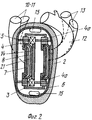
На фиг. 1 и 2 изображено искусственное сердце в двух взаимно перпендикулярных сечениях в стадии окончания систолы. In FIG. 1 and 2 show an artificial heart in two mutually perpendicular sections at the end of systole.
Искусственное сердце содержит корпус 1 с оболочкой 2, выполненные из биологически нейтрального материала, с укрепленным неподвижно в корпусе электромагнитом 3, взаимно действующим с постоянными магнитами 4 и 4 а в виде обойм, свободно перемещающихся по направляющим шпилькам 5. The artificial heart contains a
Магнитные обоймы 4 и 4 а жестко соединены между собой скобами 6 и прижимными пластинами 7.
К прижимным пластинам 7 своими основаниями крепятся баллоны 8, сделанные из эластичного материала типа армированного силикона или латекса. К баллонам 8 подсоединяются при помощи патрубков (не показаны) сосуды большого и малого круга: к правому баллону - легочный ствол 9 и полые вены: нижняя 10, верхняя 11, к левому баллону - аорта 12 и легочные вены 13. Вторым основанием баллоны крепятся: правый - к перегородке электромагнита 14, левый - к корпусу 1. Внутри корпуса сверху монтируется блок управления 15, который изменяет направление тока с заданной частотой.
Блок питания 16 смонтирован в нижней части корпуса. Он обеспечивает электропитание электромагниту, который может иметь одну общую обмотку 17, но лучше в виде параллельно подключенных секционных электромагнитов 18. The power supply 16 is mounted in the lower part of the housing. It provides power to the electromagnet, which may have one
Основное питание электромагнит 3 и блок управления 14 получают от внешнего источника тока, через выведенный наружу кабель (не показан). The main power supply of the
Искусственное сердце работает следующим образом. Магнитные обоймы 4 и 4 а обращены друг к другу одноименными полюсами. Направление тока в обмотке 17 электромагнита с помощью блока управления 15 может меняться с заданной частотой, чем достигается периодическая смена полюсов электромагнита. В результате взаимодействия поля электромагнита с полями магнитных обойм происходит притяжение одной магнитной обоймы и одновременное отталкивание другой. В момент систолы (см. фиг. 1 и 2) электромагнит 3 отталкивает магнитную обойму 4 а и притягивает магнитную обойму 4. Так как магнитные обоймы 4 и 4 а при помощи прижимных пластин 7 прикреплены к основаниям эластичных баллонов 8, то вследствие отмеченных взаимодействий эластичные баллоны 8 сжимаются и выталкивают кровь в легочный ствол 9 и аорту 12, открывая при этом естественные клапаны 19 этих сосудов, а искусственные клапаны 20 верхней полой 10, нижней полой 11 и легочных вен 13 в этот момент закрыты. При диастоле магнитные обоймы 4 и 4 а перемещаются в обратном направлении и растягивают эластичные баллоны 8, засасывая кровь в полость баллонов 21 из венозных сосудов, клапаны которых 20 в этот момент открываются, а артериальные 19 закрыты. После этого цикл повторяется с частотой, регулируемой блоком управления 15. Емкость баллона должна быть 75 - 100 см3.An artificial heart works as follows.
Искусственное сердце может работать от источника питания 16, смонтированного в корпусе сердца, но в основном от наружного источника питания через кабель, выведенный через грудную стенку. (56) Авторское свидетельство СССР N 68183, кл. A 61 M 1/00, 1947. The artificial heart can work from a power source 16 mounted in the heart, but mainly from an external power source through a cable through the chest wall. (56) Copyright certificate of the USSR N 68183, cl. A 61
Claims (1)
Priority Applications (1)
| Application Number | Priority Date | Filing Date | Title |
|---|---|---|---|
| SU4449419 RU2007191C1 (en) | 1988-06-27 | 1988-06-27 | Artificial heart |
Applications Claiming Priority (1)
| Application Number | Priority Date | Filing Date | Title |
|---|---|---|---|
| SU4449419 RU2007191C1 (en) | 1988-06-27 | 1988-06-27 | Artificial heart |
Publications (1)
| Publication Number | Publication Date |
|---|---|
| RU2007191C1 true RU2007191C1 (en) | 1994-02-15 |
Family
ID=21385080
Family Applications (1)
| Application Number | Title | Priority Date | Filing Date |
|---|---|---|---|
| SU4449419 RU2007191C1 (en) | 1988-06-27 | 1988-06-27 | Artificial heart |
Country Status (1)
| Country | Link |
|---|---|
| RU (1) | RU2007191C1 (en) |
-
1988
- 1988-06-27 RU SU4449419 patent/RU2007191C1/en active
Similar Documents
| Publication | Publication Date | Title |
|---|---|---|
| US6197055B1 (en) | Single chamber mechanical heart | |
| US3842440A (en) | Implantable linear motor prosthetic heart and control system therefor | |
| US6969345B2 (en) | Miniature, pulsatile implantable ventricular assist devices and methods of controlling ventricular assist devices | |
| US20120323318A1 (en) | Flexible magnetic membrane based actuation system and devices involving the same | |
| US10933181B2 (en) | Implantable pump system having a rectangular membrane | |
| GB1444614A (en) | Permanently implantable artificial heart | |
| CA2916350C (en) | Artificial ventricles | |
| US6264601B1 (en) | Implantable ventricular assist device | |
| US3768931A (en) | Magnetically actuated pump with flexible membrane | |
| US4213207A (en) | Artificial heart and method of pumping blood | |
| CA1061952A (en) | Artificial heart propelled by respiratory muscles | |
| US3513486A (en) | Heart assistance pump | |
| Goodman et al. | Left ventricular assist devices: a historical perspective at the intersection of medicine and engineering | |
| JP2652645B2 (en) | Ferrofluid pump for pumping biological fluid | |
| US11273300B2 (en) | Magnetically suspended blood driving piston circulatory assist device | |
| RU2007191C1 (en) | Artificial heart | |
| US20100298932A1 (en) | Implantable artificial ventricle having low energy requirement | |
| RU201911U1 (en) | Blood flow control device for extracorporeal circulatory support systems | |
| Xia | A bionic artificial heart blood pump driven by permanent magnet located outside human body | |
| CN102028980B (en) | Bionic artificial heart blood pump linearly driven by permanent magnetic field in vitro | |
| Pierce et al. | An electric artificial heart for clinical use | |
| JP2022524774A (en) | Positive displacement shuttle pump heart and VAD | |
| Jeong et al. | Development of a closed air loop electropneumatic actuator for driving a pneumatic blood pump | |
| RU2387457C1 (en) | Artificial heart | |
| Fukui et al. | Development of the assisted artificial heart with linear motor actuator |