RU200073U1 - DEVICE FOR MEASURING THE TRANSEPITELIAL ELECTRIC RESISTANCE OF MAMMAL BARRIER CELLS - Google Patents
DEVICE FOR MEASURING THE TRANSEPITELIAL ELECTRIC RESISTANCE OF MAMMAL BARRIER CELLS Download PDFInfo
- Publication number
- RU200073U1 RU200073U1 RU2020117013U RU2020117013U RU200073U1 RU 200073 U1 RU200073 U1 RU 200073U1 RU 2020117013 U RU2020117013 U RU 2020117013U RU 2020117013 U RU2020117013 U RU 2020117013U RU 200073 U1 RU200073 U1 RU 200073U1
- Authority
- RU
- Russia
- Prior art keywords
- biochip
- contacts
- microfluidic
- cells
- spring
- Prior art date
Links
Images

Classifications
-
- G—PHYSICS
- G01—MEASURING; TESTING
- G01N—INVESTIGATING OR ANALYSING MATERIALS BY DETERMINING THEIR CHEMICAL OR PHYSICAL PROPERTIES
- G01N27/00—Investigating or analysing materials by the use of electric, electrochemical, or magnetic means
- G01N27/02—Investigating or analysing materials by the use of electric, electrochemical, or magnetic means by investigating impedance
Abstract
Полезная модель относится к устройствам для работы с клетками тканей человека, бактериальными клетками, а также с культурами вирусов, которая может быть использована для создания клеточных моделей барьерных тканей человека в условиях сокультивирования с бактериальными и вирусными культурами для моделирования взаимодействия клеток и изучения бактериальной адгезии в режиме онлайн мониторинга, изучения динамики трансэпителиального/трансэндотелиального сопротивления, а также для испытаний лекарственных препаратов.Разработанное устройство представляет собой многоразовую конструкцию (микроплату-держатель для биочипа), состоящую из двух текстолитовых плат, выполненную с возможностью размещения между ними микрофлюидного чипа стандартного размера, двух самоклеящихся покровных стекол с напыленными на них титановыми электродами, соединяющихся между собой подпружиненными электрическими контактами и фиксированными коннекторами между собой. Устройство выполнено из текстолита и совместимо с большинством коммерчески доступных биочипов, имеющих размеры предметного стекла (25±1 мм x 75±1 мм).The utility model relates to devices for working with human tissue cells, bacterial cells, as well as with virus cultures, which can be used to create cellular models of human barrier tissues under conditions of co-cultivation with bacterial and viral cultures to simulate cell interaction and study bacterial adhesion in the mode online monitoring, studying the dynamics of transepithelial / transendothelial resistance, as well as for testing drugs. The developed device is a reusable structure (microchip holder for a biochip), consisting of two textolite boards, made with the possibility of placing a microfluidic chip of a standard size, two self-adhesive cover glasses with titanium electrodes deposited on them, interconnected by spring-loaded electrical contacts and fixed connectors to each other. The device is made of textolite and is compatible with most commercially available biochips with the dimensions of a slide (25 ± 1 mm x 75 ± 1 mm).
Description
Область техники, к которой относится полезная модельThe technical field to which the utility model belongs
Полезная модель относится к измерительной технике и может быть использована для измерения спектра импеданса биологических тканей, органов, клеток или клеточных моделей млекопитающих, размещенных в измерительных ячейках микрофлюидного чипа. В частности, полезная модель позволяет оценивать функциональное состояние клеточных моделей в образцах in vitro в биологических экспериментах в условиях вирусного и бактериального заражения в режиме реального времени методом измерения динамики изменений трансэпителиального/трансэндотелиального сопротивления, включая клеточные модели на основе дифференцированной в микрофлюидной системе линии аденокарциномы кишечника Caco-2 или линии аденокарциномы лёгких Calu-3 для исследования вируса SARS-CoV-2. Заявляемое решение также может быть использовано для исследования влияния различных препаратов (в т.ч. противовирусных и антибактериальных лекарственных препаратов) на клетки в условиях in vitro, а также для изучения адгезии бактериальных клеток.The utility model relates to measuring technology and can be used to measure the impedance spectrum of biological tissues, organs, cells, or mammalian cell models placed in the measuring cells of a microfluidic chip. In particular, the utility model makes it possible to evaluate the functional state of cell models in in vitro samples in biological experiments under viral and bacterial infection in real time by measuring the dynamics of changes in transepithelial / transendothelial resistance, including cell models based on the Caco line of intestinal adenocarcinoma differentiated in the microfluidic system -2 or line of lung adenocarcinoma Calu-3 for the study of the SARS-CoV-2 virus. The claimed solution can also be used to study the effect of various drugs (including antiviral and antibacterial drugs) on cells in vitro , as well as to study the adhesion of bacterial cells.
Уровень техникиState of the art
Культивирование клеток в микрофлюидных системах на сегодняшний день является одним из наиболее перспективных подходов, обеспечивающих in vitro условия, сходные с условиями in vivo, для поддержания жизнеспособности, функциональной активности и стабильности клеточных культур в течение длительного времени (до 28 дней), с возможностью регистрации изменения параметров, характеризующих функциональный статус клеток на молекулярном уровне. Изучение клеточных структур в естественном состоянии позволяет получить новые знания о процессах, происходящих в клетках, определить способы воздействия на клетки, приводящие к тому или иному результату. Это является важным при создании эффективных лекарственных средств и разработке новых методов лечения заболеваний. Наиболее предпочтительным для изучения SARS является использование клеток кишечника Caco-2, которые экспрессируют ангиотензин превращающий фермент 2 (ACE2) и сериновую протеазу TMPRSS2, через которые происходит заражение организма новым коронавирусом SARS-CoV и позволяет реплицировать вирус в условиях in vitro (Mossel, E. C. et al. Exogenous ACE2 Expression Allows Refractory Cell Lines To Support Severe Acute Respiratory Syndrome Coronavirus Replication. J. Virol. 79, 3846–3850 (2005)). Поэтому в настоящее время клетки Caco-2 активно применяются для поиска противовирусных препаратов. Culturing cells in microfluidic systems today is one of the most promising approaches that provide in vitro conditions similar to in vivo conditions for maintaining the viability, functional activity and stability of cell cultures for a long time (up to 28 days), with the possibility of registering changes parameters characterizing the functional status of cells at the molecular level. The study of cellular structures in a natural state allows one to gain new knowledge about the processes occurring in cells, to determine the ways of influencing cells, leading to one or another result. This is important in the creation of effective drugs and the development of new methods of treating diseases. The most preferred for the study of SARS is the use of intestinal cells Caco-2, which express angiotensin converting enzyme 2 (ACE2) and serine protease TMPRSS2, through which the body is infected with the novel SARS-CoV coronavirus and allows the virus to replicate in vitro (Mossel, EC et al. Exogenous ACE2 Expression Allows Refractory Cell Lines To Support Severe Acute Respiratory Syndrome Coronavirus Replication J. Virol. 79, 3846-3850 (2005)). Therefore, at present, Caco-2 cells are actively used to search for antiviral drugs.
Модели биологических барьеров чрезвычайно важны для исследования физиологических функций, механизмов транспорта, патологий. Слои образующих барьер эпителиальных и эндотелиальных клеток, прежде всего, характеризуются способностью формировать плотные межклеточные контакты, разделяющие апикальную и базолатеральную стороны слоя. Клетки формируют между соответствующими компартментами слой с селективной проницаемостью, контролирующий диффузию через парацеллюлярные пути и транспорт – через интрацеллюлярные. При этом, барьер не является статическим и может модулироваться различными стимулами, приводящими к его закрытию или открытию. Функционирование этого барьера необходимо для выполнения тканью своей физиологической функции. Импедансная спектрометрия является воспроизводимым и информативным методом измерения трансэпителиального или трансэндотелиального сопротивления. Метод заключается в измерении амплитуды и фазы переменного тока, при воздействии синусоидального переменного напряжения с частой обычно изменяемой в диапазоне от 1 Гц до 100 кГц. Из полученного спектра полного сопротивления путем «подгонки» модели, основанной на эквивалентной схеме, можно извлечь информацию не только об активном сопротивлении, но и реактивных компонентах сопротивления, позволяющих оценить различные параметры клеточной модели. Метод измерения трансэпителиального сопротивления является наиболее удобным и неинвазивным по сравнению с другими методами.Biological barrier models are extremely important for the study of physiological functions, transport mechanisms, pathologies. The layers of epithelial and endothelial cells that form the barrier are primarily characterized by the ability to form tight intercellular contacts separating the apical and basolateral sides of the layer. The cells form a layer with selective permeability between the corresponding compartments, which controls diffusion through the paracellular pathways and transport through the intracellular pathways. Moreover, the barrier is not static and can be modulated by various stimuli leading to its closing or opening. The functioning of this barrier is necessary for the tissue to perform its physiological function. Impedance spectrometry is a reproducible and informative method for measuring transepithelial or transendothelial resistance. The method consists in measuring the amplitude and phase of an alternating current, when exposed to a sinusoidal alternating voltage with a frequency usually varying in the range from 1 Hz to 100 kHz. From the obtained impedance spectrum by "fitting" the model based on the equivalent circuit, it is possible to extract information not only about the active resistance, but also about the reactive components of the resistance, which allows one to estimate various parameters of the cellular model. The method for measuring transepithelial resistance is the most convenient and non-invasive in comparison with other methods.
Таким образом, для исследования физиологически значимых взаимодействий микроорганизм/вирус-хозяин предпочтительно использование экспериментальных in vitro моделей, реализуемых в микрофлюидных устройствах (микрофлюидных системах или биочипах), которые способны поддерживать сложные популяции аэробной и анаэробной микробиоты в контакте с живыми тканями человека, в комбинации со средствами измерения спектра импеданса таких моделей.Thus, for the study of physiologically significant interactions microorganism / virus-host, it is preferable to use experimental in vitro models implemented in microfluidic devices (microfluidic systems or biochips) that are able to maintain complex populations of aerobic and anaerobic microbiota in contact with living human tissues, in combination with means of measuring the impedance spectrum of such models.
Из уровня техники известны различные устройства, обеспечивающие измерение импеданса биологических структур в микрофлюидных системах, в частности, в модели «кишечник-на-чипе».Various devices are known from the prior art that provide measurement of the impedance of biological structures in microfluidic systems, in particular, in the intestine-on-a-chip model.
Из патента CA3053191A1 известно устройство, в котором в микрофлюидный чип встроен мультиэлектродный массив в нижнюю часть нижний камеры и в верхнюю часть верхней камеры, соответственно. Такое решение, безусловно, дает возможность снимать точные данные, но в то же время крайне сложно в изготовлении и сборке. A device is known from CA3053191A1 in which a multi-electrode array is embedded in a microfluidic chip in the lower part of the lower chamber and in the upper part of the upper chamber, respectively. Such a solution, of course, makes it possible to take accurate data, but at the same time it is extremely difficult to manufacture and assemble.
Из патента US9513280 известно устройство, аналогичное описанному выше патенту, с той разницей, что в микрофлюидную двухкамерную ячейку в нижнюю часть камеры встроены два электрода. Само устройство имеет достаточно узкоспециализированное применение – имитацию человеческого гематоэнцефалического барьера. A device similar to the patent described above is known from US9513280, with the difference that two electrodes are built into the microfluidic two-chamber cell in the lower part of the chamber. The device itself has a rather highly specialized application - an imitation of the human blood-brain barrier.
В патентах US20140038279A1, US20160313306A1 и US20180320125A1 описаны устройства «кишечник-на-чипе», в которых измерение импеданса не предусмотрено в режиме реального времени, а его значения измеряются вне устройств.US20140038279A1, US20160313306A1 and US20180320125A1 describe gut-on-a-chip devices in which impedance measurement is not provided in real time, but impedance values are measured outside the devices.
В патенте US20190359924A1 описано устройство для сокультивирования астроцитов и эпителиальных клеток мозга. Описанная конструкция допускает измерение трансэпиттелиального сопротивления в онлайн режиме. Это технически решено внедрением электродов в тело микрофлюидного чипа, похожим способом, описанным в перечисленных выше заявках и патентах.US20190359924A1 describes a device for co-cultivating astrocytes and brain epithelial cells. The described design allows online measurement of transepithelial resistance. This is technically solved by the introduction of electrodes into the body of the microfluidic chip, in a similar way described in the above applications and patents.
Наиболее близким к заявляемой полезной модели является устройство для измерения трансэпителиального электрического сопротивления барьерных клеток млекопитающих, размещенных на мембране микрофлюидного биочипа, представленное в международной заявке WO2017106727A1. Устройство включает нижнюю подложку с размещенным на ней биочипом, снабженным двумя пластинами (покровными пленками), верхней и нижней, выполненными из оптически прозрачного материала, закрепленными с верхней и нижней сторон биочипа с помощью токопроводящей пасты, при этом на пластины нанесены металлические электроды, например, гребенчатой формы. В одном из вариантов осуществления полезной модели на покровную пленку нанесен титановый электрод толщиной 3 нм, покрытый слоем 25 нм золота, поверх которого также нанесен ещё один слой титана толщиной в 1 нм. Предпочтительным в данном изобретении является использование электродов толщиной 10-30 нм. Устройство также снабжено электрическими контактами, коннектором и интерфейсом для подключения к внешнему устройству измерения импеданса для передачи сигнала импеданса от электродов.Closest to the claimed utility model is a device for measuring transepithelial electrical resistance of mammalian barrier cells placed on the membrane of a microfluidic biochip, presented in international application WO2017106727A1. The device includes a lower substrate with a biochip placed on it, equipped with two plates (cover films), upper and lower, made of optically transparent material, fixed on the upper and lower sides of the biochip using a conductive paste, with metal electrodes applied to the plates, for example, comb-shaped. In one of the embodiments of the utility model, a 3 nm thick titanium electrode coated with a 25 nm gold layer is applied to the cover film, on top of which another 1 nm titanium layer is also deposited. Preferred in this invention is the use of electrodes with a thickness of 10-30 nm. The device is also equipped with electrical contacts, a connector and an interface for connecting to an external impedance measurement device for transferring the impedance signal from the electrodes.
В заявке WO2017106727A1 отмечено, что электрические контакты к внешнему устройству могут проходить по подложке от верней и нижней частей биочипа. Однако в материалах изобретения не раскрыты средства, обеспечивающие снятие и запись данных с электродов, подведение контактов от микрофлюидного чипа к измерительному устройству, а также подключение и передачу сигнала от электродов на устройство измерения. Наличие только одной нижней подложки не позволяет проводить микроскопическое исследование свойств барьерных клеток с одновременным измерением электрических характеристик. Для исследования клеток под микроскопом биочип необходимо извлекать из устройства для измерения импеданса, что может привести к разгерметизации ячейки и каналов чипа, и негативно повлиять на результаты эксперимента. Заявляемая конструкция устройства для измерения импеданса позволяет без извлечения из него чипа проводить как микроскопические исследования, так и измерение импеданса.In the application WO2017106727A1 it is noted that electrical contacts to an external device can pass along the substrate from the upper and lower parts of the biochip. However, the materials of the invention do not disclose the means for removing and recording data from the electrodes, bringing contacts from the microfluidic chip to the measuring device, as well as connecting and transmitting the signal from the electrodes to the measuring device. The presence of only one lower substrate does not allow microscopic examination of the properties of barrier cells with simultaneous measurement of electrical characteristics. To study cells under a microscope, the biochip must be removed from the impedance measuring device, which can lead to depressurization of the cell and the channels of the chip, and negatively affect the results of the experiment. The claimed design of the device for measuring impedance allows, without removing the chip from it, to carry out both microscopic studies and measurement of impedance.
Кроме того, выполнение подключения электродов на покровной пленке к телу микрочипа с помощью токопроводящей пасты создает риски контаминации в камерах чипа при сборке микрофлюидного устройства. Такая контаминация может сказаться на жизнеспособности клеток, создает помехи измерений и ставит под угрозу результаты эксперимента. Кроме того, сборка такого биочипа является трудоемкой и требует специальных знаний и навыков. Помимо этого, способ сборки чипа требует нагрева материалов до 60⁰С, для чего необходимо дополнительное оборудование, что также усложняет процесс изготовления устройства. Кроме того, толщина проводящего слоя, напыляемого на электропроводные пленки чипа, составляет 10-30 нм, что вызывает высокие значения сопротивления, а также приводит к повышенной хрупкости, влияющей на сложность сборки и требования к квалификации персонала.In addition, making the connection of the electrodes on the cover film to the body of the microchip using a conductive paste creates risks of contamination in the chambers of the chip during the assembly of the microfluidic device. This contamination can affect cell viability, interfere with measurements, and jeopardize experimental results. In addition, the assembly of such a biochip is laborious and requires special knowledge and skills. In addition, the method for assembling the chip requires heating the materials up to 60 ° C, which requires additional equipment, which also complicates the manufacturing process of the device. In addition, the thickness of the conductive layer deposited on the electrically conductive films of the chip is 10-30 nm, which causes high resistance values, and also leads to increased fragility, which affects the complexity of assembly and the requirements for personnel qualifications.
Таким образом, известные устройства не отличаются простотой конструкции, а также не позволяют проводить микроскопическое исследование свойств барьерных клеток с одновременным измерением электрических характеристик, с заменой, при необходимости, чипов для исследования иммобилизованных на их мембранах клеток. Кроме того, проведение измерений спектра импеданса возможно, как правило, с использованием производимых биочипов со встроенными электродами. Отсутствует универсальный подход к сборке устройств. Такая схема затрудняет процесс проведения измерений, а точность результатов будет полностью зависеть от квалификации и действий лаборанта. Как следствие существенно возрастает погрешность измерений.Thus, the known devices do not differ in simplicity of design, and also do not allow microscopic examination of the properties of barrier cells with simultaneous measurement of electrical characteristics, with replacement, if necessary, of chips for the study of cells immobilized on their membranes. In addition, measurements of the impedance spectrum are possible, as a rule, using manufactured biochips with built-in electrodes. There is no universal approach to assembling devices. Such a scheme complicates the measurement process, and the accuracy of the results will completely depend on the qualifications and actions of the laboratory assistant. As a consequence, the measurement error increases significantly.
Технической проблемой, на решение которой направлена заявляемая полезная модель, является создание простого в сборке и эксплуатации универсального устройства для измерения спектра импеданса клеточной модели в широком диапазоне частот (от 20 Гц до 20 кГц) с различной амплитудой тока (от 10 мкА до 100 мкА) в режиме реального времени, в котором возможно размещение биочипов с мембранными вставками различных производителей, имеющих стандартный размер, обеспечивающий проведение исследований с помощью микроскопии либо любых других оптических методов. The technical problem to be solved by the claimed utility model is the creation of an easy-to-assemble and operate universal device for measuring the impedance spectrum of a cell model in a wide frequency range (from 20 Hz to 20 kHz) with various current amplitudes (from 10 μA to 100 μA) in real-time mode, in which it is possible to place biochips with membrane inserts from various manufacturers, which have a standard size that allows for studies using microscopy or any other optical methods.
Раскрытие сущности полезной моделиDisclosure of the essence of the utility model
Техническим результатом является возможность проведения микроскопического исследования свойств биологических структур без извлечения биочипа из устройства, обеспечение быстроты и удобства сборки и эксплуатации устройства для измерения спектра импеданса биологических структур.The technical result is the ability to conduct a microscopic study of the properties of biological structures without removing the biochip from the device, ensuring the speed and ease of assembly and operation of the device for measuring the impedance spectrum of biological structures.
Технический результат достигается при использовании устройства для измерения трансэпителиального электрического сопротивления барьерных клеток млекопитающих, размещенных на мембране микрофлюидного биочипа, включающего The technical result is achieved when using a device for measuring the transepithelial electrical resistance of mammalian barrier cells, placed on the membrane of a microfluidic biochip, including
- две пленки (или пластины), верхнюю и нижнюю, с металлическими электродами гребенчатой формы, выполненные из оптически прозрачного материала (в т.ч. биополимера или стекла, не адсорбирующего малые молекулы или химически инертного к биологическим структурам) с возможностью размещения на верхней и нижней сторонах микрофлюидного биочипа,- two films (or plates), upper and lower, with comb-shaped metal electrodes made of optically transparent material (including biopolymer or glass that does not absorb small molecules or is chemically inert to biological structures) with the possibility of placing on the upper and the lower sides of the microfluidic biochip,
- две текстолитовые платы, снабженные смотровыми окнами (отверстиями) для визуализации барьерных клеток на мембране биочипа с помощью оптических средств, и выполненные с возможностью размещения между ними биочипа, покрытого с верхней и нижней сторон пленками с металлическими электродами, при этом каждая плата снабжена группой из четырех подпружиненных электрических контактов и двумя коннекторами, размещенными с возможностью фиксации плат между собой с обеспечением передачи сигнала импеданса от гребенчатых электродов к внешнему устройству измерения импеданса,- two textolite boards equipped with viewing windows (holes) for visualization of barrier cells on the biochip membrane using optical means, and made with the possibility of placing a biochip between them, covered on the upper and lower sides with films with metal electrodes, while each board is equipped with a group of four spring-loaded electrical contacts and two connectors placed with the possibility of fixing the boards to each other to ensure the transfer of the impedance signal from the comb electrodes to an external impedance measurement device,
- интерфейс для подключения к внешнему устройству измерения импеданса, размещенный на нижней текстолитовой плате,- interface for connecting to an external device for measuring impedance, located on the lower textolite board,
при этом группа контактов нижней платы расположена в ее центральной части, а микрофлюидный биочип и нижняя пленка снабжены отверстиями для подведения подпружиненных электрических контактов от нижней платы к контактам электродов гребенчатой формы на верхней пленке и обеспечения возможности центрирования (позиционирования) биочипа при его установке между текстолитовыми платами.in this case, the group of contacts of the lower board is located in its central part, and the microfluidic biochip and the lower film are equipped with holes for connecting the spring-loaded electrical contacts from the lower board to the contacts of comb-shaped electrodes on the upper film and providing the possibility of centering (positioning) the biochip when it is installed between the textolite boards ...
В качестве подпружиненных электрических контактов могут быть использованы контакты типа «pogo pin» (напр. контакты фирмы Harvin P70-2010045R или P70-2000045R). Контакты верхней платы предпочтительно расположены по ее краям с противоположных сторон - по два контакта. As spring-loaded electrical contacts can be used contacts of the "pogo pin" type (for example, Harvin contacts P70-2010045R or P70-2000045R). The contacts of the top board are preferably located along its edges on opposite sides - two contacts each.
Пленки снабжены покрытием из адгезионного материала для закрепления на поверхности микрофлюидного биочипа, или выполнены самоклеящимися. Пленки могут иметь толщину до 0,5 мм (предпочтительно от 0,1 до 0,2 мм). Пленки могут быть выполнены из материала, выбранного из следующего ряда: поликарбонат, SEBS, полиуретан, полиэстер, цикличный олефин сополимера, цикличный олефин полимера, нитрид кремния, полиметилметакрилат, поливинилхлорида, полистирол, полиэтилентерефталлат или стекло.The films are coated with an adhesive material for fixing on the surface of the microfluidic biochip, or are self-adhesive. The films can be up to 0.5 mm thick (preferably 0.1 to 0.2 mm). The films can be made from a material selected from the following range: polycarbonate, SEBS, polyurethane, polyester, cyclic copolymer olefin, polymer cyclic olefin, silicon nitride, polymethyl methacrylate, polyvinyl chloride, polystyrene, polyethylene terephthallate, or glass.
Площадь, занимаемая металлическими электродами гребенчатой формы, соответствует площади мембраны микрофлюидного биочипа. Гребенчатые электроды могут быть выполнены на пленках (пластинах) из титана, а также дополнительно покрыты слоем золота методом вакуумного напыления. Гребенчатые электроды имеют ширину не менее 0,5 мм и высоту (толщину слоя напыления) от 50 до 500 нм с одним или несколькими слоями металла (предпочтительно 100-200 нм).The area occupied by comb-shaped metal electrodes corresponds to the area of the microfluidic biochip membrane. Comb electrodes can be made on films (plates) of titanium, and additionally coated with a layer of gold by vacuum deposition. The comb electrodes have a width of at least 0.5 mm and a height (thickness of the deposition layer) from 50 to 500 nm with one or more metal layers (preferably 100-200 nm).
Высота (толщина) текстолитовых плат составляет от 1 до 3 мм (предпочтительно от 2 мм), что обеспечивает жесткость и надежность конструкции.The height (thickness) of textolite boards is from 1 to 3 mm (preferably from 2 mm), which ensures the rigidity and reliability of the structure.
Высота подпружиненных контактов составляет до 5 мм с ходом пружины ±0,5 мм.The height of the spring-loaded contacts is up to 5 mm with a spring travel of ± 0.5 mm.
Диаметр отверстий в пленке и теле микрофлюидного чипа для проведения подпружиненных электрических контактов составляет 2,2 мм.The diameter of the holes in the film and in the body of the microfluidic chip for conducting spring-loaded electrical contacts is 2.2 mm.
В конкретном варианте выполнения устройства коннекторы выполнены 10-пиновыми, на каждой плате размещены с ее противоположных сторон.In a specific embodiment of the device, the connectors are made 10-pins, on each board they are located on its opposite sides.
Микрофлюидный биочип и мембрана биочипа могут быть выполнены из материалов, выбранных из следующего ряда: поликарбонат, SEBS, полиуретан, полиэстер, цикличный олефин сополимера, нитрид кремния, полиметилметакрилат, поливинилхлорид, полистирол, полиэтилентерефталлат. Микрофлюидный биочип предпочтительно имеет двухкамерную структуру ячейки, разделенную полупроницаемой мембраной, две ячейки с мембранами для иммобилизации клеток млекопитающих и до восьми распределительных каналов для входа и выхода питательных сред. Микрофлюидный биочип имеет размеры, соответствующие размеру предметного стекла микроскопа (25±1 мм x 75±1 мм); высоту (толщину) от 1,5 до 2,5 мм.The microfluidic biochip and the biochip membrane can be made of materials selected from the following range: polycarbonate, SEBS, polyurethane, polyester, cyclic copolymer olefin, silicon nitride, polymethyl methacrylate, polyvinyl chloride, polystyrene, polyethylene terephthallate. The microfluidic biochip preferably has a two-chamber cell structure, separated by a semipermeable membrane, two cells with membranes for immobilizing mammalian cells, and up to eight distribution channels for the entry and exit of nutrient media. The microfluidic biochip is sized to match the microscope slide (25 ± 1 mm x 75 ± 1 mm); height (thickness) from 1.5 to 2.5 mm.
В конструкции устройства площадь электродов перекрывает площадь мембраны в ячейке чипа практически полностью и такое решение приводит к тому, что электрическое поле в чипе будет распределено равномерно и сконцентрировано в области расположения электродов. Таким образом, вся барьерная ткань будет вносить вклад в значения измеряемых электрических характеристик, что будет приводить к получению более достоверных и точных результатов измерений.In the design of the device, the area of the electrodes overlaps the area of the membrane in the chip cell almost completely, and this solution leads to the fact that the electric field in the chip will be uniformly distributed and concentrated in the area of the electrode location. Thus, all of the barrier tissue will contribute to the measured electrical values, resulting in more reliable and accurate measurements.
Краткое описание чертежейBrief Description of Drawings
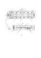
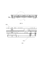
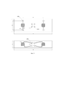
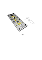
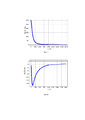
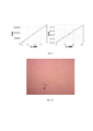
Полезная модель поясняется чертежами, где на фиг. 1 представлен чертеж заявляемого устройства (вид сверху и вид сбоку); на фиг. 2 представлено расположение подпружиненных контактов для электрода (вид сбоку); на фиг. 3 изображен вариант напыления электродов на нижнюю и верхнюю пленки (пластины); на фиг. 4 показано устройство в сборе, на фиг.5 – верхняя и нижняя текстолитовые платы, на фиг.6 – микрофлюидный биочип с нанесенными на его поверхность пленками, содержащими металлические электроды гребенчатой формы; на фиг.7 – данные зависимости мнимой части импеданса от частоты электрического тока, на фиг.8 – данные зависимости действительной части импеданса от частоты электрического тока, на фиг. 9 – калибровочные кривые зависимости интенсивности флуоресценции от концентрации для низких (0-1,75 мкМ) и высоких (1,75-60 мкМ) концентраций субстрата, соответственно, на фиг.10 – результаты микроскопии, полученной с помощью устройства на 4й день культивирования клеток Caco-2.The utility model is illustrated by drawings, where FIG. 1 shows a drawing of the claimed device (top view and side view); in fig. 2 shows the location of the spring-loaded contacts for the electrode (side view); in fig. 3 shows a variant of spraying electrodes on the lower and upper films (plates); in fig. Figure 4 shows the assembled device, figure 5 - upper and lower textolite boards, figure 6 - microfluidic biochip with films deposited on its surface containing comb-shaped metal electrodes; in Fig. 7 - data of the dependence of the imaginary part of the impedance on the frequency of the electric current, in Fig. 8 - data on the dependence of the real part of the impedance on the frequency of the electric current, in Fig. 9 - calibration curves of the dependence of the fluorescence intensity on the concentration for low (0-1.75 μM) and high (1.75-60 μM) substrate concentrations, respectively, in Fig. 10 - the results of microscopy obtained using the device on the 4th day of cultivation Caco-2 cells.
Позициями на чертежах обозначены: 1 – интерфейс подключения к устройству измерения и записи импеданс спектров; 2 – коннекторы, соединяющие и фиксирующие верхнюю и нижнюю текстолитовые платы устройства между собой, 3 – ячейки биочипа для сокультивирования клеток; 4 – верхняя камера ячейки биочипа; 5 – нижняя камера ячейки биочипа; 6 – полупроницаемая мембрана биочипа; 7 – силиконовые упоры, поддерживающие упругость конструкции; 8 – подпружиненные электрические контакты для соединения с электродами, осуществляющими измерение импеданса барьерных клеток, 9 – пленки (покрывные пленки или пластины). Positions in the drawings indicate: 1 - interface for connecting to a device for measuring and recording the impedance of spectra; 2 - connectors connecting and fixing the upper and lower textolite boards of the device with each other, 3 - biochip cells for co-cultivation of cells; 4 - upper chamber of the biochip cell; 5 - lower chamber of the biochip cell; 6 - semi-permeable membrane of the biochip; 7 - silicone stops supporting the elasticity of the structure; 8 - spring-loaded electrical contacts for connection with electrodes that measure the impedance of barrier cells, 9 - films (covering films or plates).
Осуществление полезной моделиImplementation of the utility model
Ниже представлено подробное описание конструкции многоразового устройства, обеспечивающего измерение динамики трансэпителиального/трансэндотелиального сопротивления в реальном времени барьерных клеток млекопитающих, размещенных в ячейках коммерчески доступных микрофлюидных чипов, предназначенных для сокультивирования барьерных тканей млекопитающих с бактериальными клетками, с культурами вирусов, моделирования взаимодействия клеток с микробами и вирусами, для изучения бактериальной адгезии на эпителиальных клетках в режиме онлайн мониторинга, испытаний лекарственных препаратов. Заявляемое устройство по своей функции выступает в качестве держателя микрофлюидного чипа и представляет собой конструкцию, состоящую из двух печатных текстолитовых плат (микроплат-держателей для биочипа), выполненных с возможностью размещения между ними биочипа, и снабженными фиксированными коннекторами, а также из двух самоклеящихся покровных пленок (или пластин) с напыленными на них металлическими, например, титановыми гребенчатыми электродами, соединяемыми с подпружиненными электрическими контактами. Фиксированные коннекторы позволяют жестко закрепить верхнюю и нижнюю платы устройства между собой. Подпружиненные контакты работают в диапазоне ± 0,5 мм, что позволяет варьировать ширину используемых в устройстве микрофлюидных чипов от 1,5 до 2,5 мм. Устройство выполнено из текстолита и совместимо с большинством коммерчески доступных биочипов, чьи размеры составляют стандартный размер предметного стекла (ширина х длина 25±1 мм x 75±1 мм).Below is a detailed description of the design of a reusable device that provides real-time measurement of the dynamics of transepithelial / transendothelial resistance of mammalian barrier cells located in the cells of commercially available microfluidic chips designed for co-cultivation of mammalian barrier tissues with bacterial cells, with viral cultures, modeling the interaction of cells with microbes, and viruses, to study bacterial adhesion on epithelial cells online monitoring, drug testing. The device according to its function acts as a microfluidic chip holder and is a structure consisting of two printed textolite boards (microchip holders for a biochip), made with the possibility of placing a biochip between them, and equipped with fixed connectors, as well as two self-adhesive cover films (or plates) with metal, for example, titanium comb electrodes deposited on them, connected to spring-loaded electrical contacts. Fixed connectors allow you to rigidly attach the top and bottom device boards to each other. The spring-loaded contacts operate in the range of ± 0.5 mm, which allows the width of the microfluidic chips used in the device to vary from 1.5 to 2.5 mm. The device is made of PCB and is compatible with most commercially available biochips, whose dimensions are equal to the standard size of a glass slide (width x length 25 ± 1 mm x 75 ± 1 mm).
Печатные текстолитовые платы могут быть выполнены с полимерным покрытием или без него, на которые нанесены медные дорожки. На верхней плате медные дорожки соединяют площадки подключения подпружиненных электродов с площадками под фиксированные разъемы, для обеспечения передачи сигнала для измерения импеданса с электрода, расположенного на нижней покровной пленке микрофлюидного чипа. На нижней плате дорожки расположены таким образом, чтобы соединять площадки подключения подпружиненных электродов с площадками под фиксированные коннекторы, а также соединять фиксированные разъемы и интерфейс подключения, таким образом, чтобы все сигналы от электродов верхней и нижней покровных пленок подходили в интерфейс подключения устройства измерения и записи импеданс-спектров. Printed textolite boards can be made with polymer coating or without it, on which copper tracks are applied. On the top board, copper traces connect the spring-loaded electrode pads to the fixed connector pads to provide signal transmission for impedance measurements from the electrode located on the bottom cover film of the microfluidic chip. On the bottom board, the tracks are arranged in such a way as to connect the pads for connecting the spring-loaded electrodes with the pads for fixed connectors, as well as connect the fixed connectors and the connection interface, so that all signals from the electrodes of the upper and lower cover films fit into the connection interface of the measuring and recording device impedance spectra.
В конкретном варианте осуществления полезной модели габариты нижней платы составляют 25,5 х 100 мм, габариты верхней платы составляют 23 х 92 мм. In a specific embodiment of the utility model, the dimensions of the bottom board are 25.5 x 100 mm, and the dimensions of the top board are 23 x 92 mm.
На нижней текстолитовой плате закреплены: On the lower textolite board are fixed:
1) интерфейс подключения устройства измерения и записи импеданс-спектров, например, разъем типа «Registered Jack» (RJ-25 или RJ-45 или аналогичные) либо разъем типа «Low Insertion Force Contact» (WR-FPC SMT LIF Horizontal Top или аналогичные), к которому подведены 4 контакта от электродов на микрофлюидном чипе;1) interface for connecting a device for measuring and recording impedance spectra, for example, a "Registered Jack" connector (RJ-25 or RJ-45 or similar) or a "Low Insertion Force Contact" connector (WR-FPC SMT LIF Horizontal Top or similar ), to which 4 contacts are connected from the electrodes on the microfluidic chip;
2) фиксированные коннекторы типа «Dual Socket Header Male», например, WR-PHD THT Straight Dual Socket Header или аналогичные, которые соединяют контакты с верхней и нижней платы, а также отвечают за надежность конструкции в собранном виде;2) fixed connectors of the "Dual Socket Header Male" type, for example, WR-PHD THT Straight Dual Socket Header or similar, which connect the contacts from the top and bottom boards, and are also responsible for the reliability of the assembled structure;
3) четыре подпружиненных электрических контакта (тип «pogo pin», например контакты P70-20X0045R производства фирмы «Harwin» или аналогичные), расположенные в середине платы с формированием фигуры в виде квадрата, обеспечивающие соединение с электродами верхней покровной пленки и отвечающие за передачу сигнала импеданса до интерфейса подключения устройств измерения;3) four spring-loaded electrical contacts (type "pogo pin", for example, contacts P70-20X0045R manufactured by "Harwin" or similar), located in the middle of the board with the formation of a square shape, providing connection to the electrodes of the upper cover film and are responsible for signal transmission impedance to the interface for connecting measurement devices;
4) силиконовые (либо аналогичные) упоры, изготовленные в форме круглой таблетки, закрепленные в центре специальных технологических отверстий на плате, например, в количестве 4 штук, расположенные по периметру, отвечающие за надежность конструкции устройства в сборе;4) silicone (or similar) stops made in the form of a round tablet, fixed in the center of special technological holes on the board, for example, in an amount of 4 pieces, located around the perimeter, responsible for the reliability of the assembly of the device;
На верхней текстолитовой плате закреплены: On the upper textolite board are fixed:
1) фиксированные коннекторы типа «Dual Socket Header Female», например, WR-PHD THT Straight Dual Socket Header или аналогичные, которые соединяют контакты верхней и нижней плат, а также отвечают за надежность конструкции в собранном виде;1) fixed connectors of the "Dual Socket Header Female" type, for example, WR-PHD THT Straight Dual Socket Header or similar, which connect the contacts of the upper and lower boards, and are also responsible for the reliability of the assembled structure;
2) силиконовый (либо аналогичный) упор, изготовленный в форме круглой таблетки, закрепленный по центру платы в специальном технологическом отверстии, отвечающий за надежность конструкции устройства в сборе;2) a silicone (or similar) stop made in the form of a round tablet, fixed in the center of the board in a special technological hole, which is responsible for the reliability of the assembly of the device;
3) четыре подпружиненных электрических контакта (тип «pogo pin», например контакты P70-20X0045R производства фирмы «Harwin» или аналогичные), расположенные по периметру платы, обеспечивающие соединение с электродами нижней покровной пленки и отвечающие за передачу сигнала импеданса до фиксированных коннекторов.3) four spring-loaded electrical contacts (type "pogo pin", for example, contacts P70-20X0045R manufactured by "Harwin" or similar), located along the perimeter of the board, providing connection to the electrodes of the lower cover film and responsible for transmitting the impedance signal to the fixed connectors.
Все пассивные компоненты плат, указанные выше, помещаются в технологические отверстия, а контакты к ним припаиваются.All the passive components of the boards mentioned above are placed in the technological holes, and the contacts are soldered to them.
Для подведения подпружиненных контактов от верхней платы устройства, в любом из коммерчески доступных микрофлюидных чипов соответствующего дизайна выполняют отверстия в соответствии с расположением подпружиненных контактов: четыре отверстия по периметру и четыре – в центре чипа. В нижней покровной пленке также выполняют четыре отверстия по центру пленки. Верхняя покровная пленка выполнена с размерами, покрывающими верхнюю выступающую часть микрофлюидного чипа (фиг. 3). To bring spring-loaded contacts from the top board of the device, holes are made in any of the commercially available microfluidic chips of the corresponding design in accordance with the arrangement of the spring-loaded contacts: four holes around the perimeter and four holes in the center of the chip. The bottom release liner also has four holes in the center of the film. The upper cover film is sized to cover the upper protruding part of the microfluidic chip (Fig. 3).
Электроды, дорожки и площадки для подключения подпружиненных контактов могут быть выполнены на покровных пленках любыми известными из уровня техники способами, например с помощью вакуумного напыления металлов до получения ширины титанового напыления не менее 0,5 мм и высоты от 50 до 500 нм с одним или несколькими слоями металла с предпочтительным диапазоном 100-200 нм (фиг. 3).Electrodes, tracks and pads for connecting spring-loaded contacts can be made on cover films by any methods known from the prior art, for example, by vacuum deposition of metals to obtain a titanium deposition width of at least 0.5 mm and a height of 50 to 500 nm with one or more metal layers with a preferred range of 100-200 nm (Fig. 3).
Покровные стекла с электродами для такой модели изготавливают любым известным из уровня техники способом вакуумного напыления металлов, например титана. Особенностью электродов является их симметричная гребенчатая форма, создающая достаточно однородное электромагнитное поле в измерительной ячейке и обеспечивающая точные измерения величины импеданса в ходе экспериментов.Cover glasses with electrodes for such a model are made by any method known from the prior art by vacuum deposition of metals, for example titanium. A feature of the electrodes is their symmetric comb shape, which creates a sufficiently uniform electromagnetic field in the measuring cell and provides accurate measurements of the impedance value during experiments.
Электроды рассчитаны на четырех-электродную схему измерений. Интерфейс подключения находится на нижней плате-держателе и совместим с любым устройством измерения и записи импеданс спектров.The electrodes are designed for a four-electrode measurement scheme. The connection interface is located on the bottom plate-holder and is compatible with any device for measuring and recording impedance spectra.
Биочип (микробиореактор) может быть изготовлен из любого нетоксичного и неадсорбирующего малые молекулы полимера, и, как правило, имеет двухкамерную структуру, разделенную проницаемой мембраной. Биочип и верхнее покровное стекло имеют по 4 отверстия для подведения контактов электрода от покровных стекол к плате-держателю, а также для центровки (точного позиционирования) чипа и покровных стекол в конструкции устройства. В случае использования коммерчески доступных чипов отверстия в чипе и покровном стекле изготавливают сверлением. Данные отверстия облегчают правильную сборку чипа и минимизируют экспериментальные ошибки, которые могут быть допущены лаборантами в связи с недостаточностью опыта в сборке подобных устройств. A biochip (microbioreactor) can be made of any non-toxic and non-adsorbing small molecule polymer, and, as a rule, has a two-chamber structure, separated by a permeable membrane. The biochip and the upper cover slip each have 4 holes for bringing the electrode contacts from the cover slips to the holder plate, as well as for centering (precise positioning) of the chip and cover slips in the device structure. In the case of using commercially available chips, holes in the chip and coverslip are made by drilling. These holes facilitate correct chip assembly and minimize experimental errors that can be made by laboratory technicians due to lack of experience in assembling such devices.
Таким образом, заявляемая полезная модель предлагает достаточно универсальное решение в области создания микрофлюидных систем на базе коммерчески доступных микрофлюидных биочипов для измерения трансэпителиального или трансэндотелиального сопротивления барьерных клеток млекопитающих в реальном времени. Предложенные модификации чипа просты в изготовлении и не требуют специального оборудования. Сверление может осуществляться как на лабораторных установках ЧПУ, так и вручную.Thus, the claimed utility model offers a fairly universal solution in the field of creating microfluidic systems based on commercially available microfluidic biochips for measuring transepithelial or transendothelial resistance of mammalian barrier cells in real time. The proposed modifications of the chip are easy to manufacture and do not require special equipment. Drilling can be carried out both on laboratory CNC machines and manually.
Пример реализации полезной моделиAn example of a utility model implementation
Для проведения изменений трансэпителиального электрического сопротивления барьерных клеток было изготовлено устройство, состоящее из двух текстолитовых плат, соединяющихся двумя 10-пиновыми разъемами, фиксирующими конструкцию; габариты нижней платы составляли 25,5 х 100 мм, верхней платы - 23 х 92 мм; высота текстолитовых плат может варьироваться в диапазоне от 1,0 до 3 мм, предпочтительно 2 мм; нижняя плата была снабжена интерфейсом для подключения к устройству измерения и записи импеданс спектров БАВР.941413.000; верхняя и нижняя плата были снабжены подпружиненными контактами, по четыре контакта на каждую плату, диаметр которых составлял 2 мм, высота 5 мм и ход пружины находился в пределах ±0,5 мм.To carry out changes in the transepithelial electrical resistance of the barrier cells, a device was made consisting of two textolite boards connected by two 10-pin connectors that fix the structure; the dimensions of the bottom board were 25.5 x 100 mm, the top board was 23 x 92 mm; the height of the textolite boards can vary in the range from 1.0 to 3 mm, preferably 2 mm; the bottom board was equipped with an interface for connecting to a device for measuring and recording the impedance of spectra BAVR.941413.000; the top and bottom boards were equipped with spring-loaded contacts, four contacts for each board, the diameter of which was 2 mm, the height of 5 mm, and the spring travel was within ± 0.5 mm.
Исследование проводилось с использованием микрофлюидного биочипа с полупроницаемыми мембранами производства фирмы Microfluidic Chip Shop (Германия), модель 480, с габаритными размерами 25±1 мм x 75±1 мм, содержащего две ячейки для культивирования клеток, которые разделены полупроницаемой мембраной, образуя по 2 камеры (под и над мембраной) объемом по 100 мкл, снабженные 8 микрофлюидными каналами для питательных сред. The study was carried out using a microfluidic biochip with semi-permeable membranes manufactured by Microfluidic Chip Shop (Germany), model 480, with dimensions of 25 ± 1 mm x 75 ± 1 mm, containing two cells for cell cultivation, which are separated by a semipermeable membrane, forming 2 chambers (under and above the membrane) with a volume of 100 μl, equipped with 8 microfluidic channels for culture media.
Для измерения импеданса клеточной модели барьерной ткани на полупроницаемые мембраны высаживали по 20000 клеток линии Caco-2 и культивировали в CO2-инкубаторе. В качестве питательной среды была использована среда MEM с добавлением 20% по объему фетальной бычьей сыворотки в проточном режиме при скорости 20 мкл/час. Через 4 дня после начала эксперимента к микрофлюидной системе подключали устройство измерения и записи импеданс-спектров (УИЗИС-1, БАВР.941413.000) и измеряли импеданс при комнатной температуре в диапазоне частот 80 – 20000 Гц (160 точек). Полученные данные зависимости мнимой и действительной части импеданса от частоты электрического тока представлены на фиг.7 и 8. To measure the impedance of the cell model of the barrier tissue, 20,000 Caco-2 cells were planted on semipermeable membranes and cultured in a CO 2 incubator. As a nutrient medium, MEM medium was used with the addition of 20% by volume fetal bovine serum in a flow-through mode at a rate of 20 μl / h. 4 days after the start of the experiment, a device for measuring and recording impedance spectra (UIZIS-1, BAVR.941413.000) was connected to the microfluidic system, and the impedance was measured at room temperature in the frequency range 80 - 20000 Hz (160 points). The data obtained for the dependence of the imaginary and real parts of the impedance on the frequency of the electric current are presented in Figs. 7 and 8.
Для подтверждения эффективности метода TEER с испозованием заявляемого устройства в целях оценки барьерной функции экспериментальных моделей кишечника использовали модельный субстрат – краситель люциферовый желтый. Данный краситель часто применяется для оценки целостности in vitro моделей кишечника, так как транспортируется только за счет пассивной диффузии [Hidalgo I.J., Raub T.J., Borchardt R.T. Characterization of the Human Colon Carcinoma Cell Line (Caco-2) as a Model System for Intestinal Epithelial Permeability // Gastroenterology. American Gastroenterological Association, 1989. Vol. 96, № 2. P. 736–749.]. После 4 дней культивирования чипов с клетками Caco-2 в апикальную часть (контур, содержащий клетки) со скоростью 500 мкл/ч подавали 60 мкМ раствор люциферового желтого (в качестве растворителя был использован солевой раствор Хенкса, конечная концентрация ДМСО была доведена до 1% об.) а в базальную – солевой раствор Хенкса с 1% об. ДМСО. Затем чипы инкубировали в клеточном инкубаторе (5% СО2, 37ºС) в течение 1 часа. Растворы, прошедшие через чипы, собирали для дальнейшего анализа. Концентрацию люциферового желтого в апикальной и базальной частях определяли при помощи планшетного мультидетектора SpectraMax i3 (Molecular Devices). Методика расчета коэффициента проницаемости по данным об интенсивности флуоресценции субстрата, прошедшего через клеточный слой, была описана ранее [Sugano K. et al. Optimized conditions of bio-mimetic artificial membrane permeation assay // Int. J. Pharm. 2001. Vol. 228, № 1–2. P. 181–188.]. Для люциферового желтого были построены калибровочные кривые «интенсивность флуоресценции-концентрация» для низких (0-1,75 мкМ) и высоких (1,75-60 мкМ) концентраций субстрата (фиг. 9). Полученные значения коэффициента проницаемости, определенные для монослоя дифференцированных клеток Caco-2, хорошо согласуются с опубликованными ранее экспериментальными данными [Nožini D., Mili A., Mikac L. Assessment of Macrolide Transport Using PAMPA, Caco-2 and MDCKII-hMDR1 Assays // Croat. Chem. acta. 2010. Vol. 83, № 3. P. 323–331., Kauffman A.L. et al. Alternative functional in vitro models of human intestinal epithelia // Front. Pharmacol. 2013. Vol. 4, № July. P. 1–18.]. Коэффициент проницаемости около 4 нм/с свидетельствует о наличии плотных межклеточных контактов в монослое Caco-2 (один из характерных признаков дифференцировки эпителиальных клеток), что согласуется с полученными ранее значениями TEER.To confirm the effectiveness of the TEER method with the use of the proposed device in order to assess the barrier function of experimental intestinal models, a model substrate - lucifer yellow dye was used. This dye is often used to assess the integrity of in vitro intestinal models, since it is transported only by passive diffusion [Hidalgo I.J., Raub T.J., Borchardt R.T. Characterization of the Human Colon Carcinoma Cell Line (Caco-2) as a Model System for Intestinal Epithelial Permeability // Gastroenterology. American Gastroenterological Association, 1989. Vol. 96, No. 2. P. 736-749.]. After 4 days of culturing chips with Caco-2 cells, 60 μM Lucifer yellow solution was fed into the apical part (circuit containing cells) at a rate of 500 μL / h (Hanks saline solution was used as a solvent, the final concentration of DMSO was brought to 1% by volume. .) and in the basal - Hanks saline solution with 1% vol. DMSO. Then the chips were incubated in a cell incubator (5% CO2, 37 ° C) for 1 hour. The solutions passed through the chips were collected for further analysis. The concentration of Lucifer yellow in the apical and basal parts was determined using a SpectraMax i3 multi-plate detector (Molecular Devices). The method for calculating the permeability coefficient from data on the fluorescence intensity of the substrate passed through the cell layer was described earlier [Sugano K. et al. Optimized conditions of bio-mimetic artificial membrane permeation assay // Int. J. Pharm. 2001. Vol. 228, no. 1–2. P. 181-188.]. For Lucifer yellow, fluorescence intensity-concentration calibration curves were constructed for low (0-1.75 μM) and high (1.75-60 μM) substrate concentrations (FIG. 9). The obtained values of the permeability coefficient determined for the monolayer of differentiated Caco-2 cells are in good agreement with the previously published experimental data [Nožini D., Mili A., Mikac L. Assessment of Macrolide Transport Using PAMPA, Caco-2 and MDCKII-hMDR1 Assays // Croat. Chem. acta. 2010. Vol. 83, No. 3. P. 323-331., Kauffman A.L. et al. Alternative functional in vitro models of human intestinal epithelia // Front. Pharmacol. 2013. Vol. 4, no. July. P. 1-18.]. A permeability coefficient of about 4 nm / s indicates the presence of tight intercellular contacts in the Caco-2 monolayer (one of the characteristic signs of epithelial cell differentiation), which is consistent with the previously obtained TEER values.
Заявляемое устройство с размещенными на мембране микрофлюидного чипа клетками также было использовано для проведения микроскопического исследования. Данные микроскопии клеточного монослоя через 21 день показаны на фиг. 10. The inventive device with cells placed on the membrane of the microfluidic chip was also used for microscopic examination. Cell monolayer microscopic data after 21 days are shown in FIG. ten.
Таким образом, предлагаемое устройство обеспечивает возможность измерения импеданса на одной частоте, на нескольких частотах, снятие спектра импеданса, а также возможность проведения микроскопических исследований оптическими методами.Thus, the proposed device provides the ability to measure the impedance at one frequency, at several frequencies, to remove the impedance spectrum, as well as the ability to conduct microscopic studies by optical methods.
Заявляемая полезная модель характеризуется следующими преимуществами:The claimed utility model is characterized by the following advantages:
- позволяет осуществлять модификацию и сборку коммерчески доступных микрофлюидных чипов в микрофлюидное устройство для измерения и записи импедансных спектров;- allows for modification and assembly of commercially available microfluidic chips into a microfluidic device for measuring and recording impedance spectra;
- позволяет осуществлять точное позиционирование электродов относительно мембраны и микрофлюидного чипа и относительно друг друга за счет рассчитанного взаимного расположения подпружиненных контактов и отверстий в микрофлюидном чипе; - allows for precise positioning of electrodes relative to the membrane and microfluidic chip and relative to each other due to the calculated relative position of the spring-loaded contacts and holes in the microfluidic chip;
- сборка устройства не требует наличия специального дополнительного оборудования- assembly of the device does not require any special additional equipment
- позволяет проводить оперативное и неинвазивное считывание данных с помощью любого устройства измерения и записи импеданс спектров;- allows for prompt and non-invasive data reading using any device for measuring and recording the impedance of spectra;
- позволяет осуществлять неинвазивное измерение и запись импеданс спектров барьерных клеток млекопитающих в микрофлюидных чипах в условиях сокультивирования с бактериями или вирусами;- allows for non-invasive measurement and recording of the impedance spectra of mammalian barrier cells in microfluidic chips under conditions of co-cultivation with bacteria or viruses;
- позволяет проводить неинвазивное наблюдение в реальном времени с помощью любых оптических методов, например микроскопии. - allows for non-invasive observation in real time using any optical methods, such as microscopy.
Claims (22)
Priority Applications (1)
| Application Number | Priority Date | Filing Date | Title |
|---|---|---|---|
| RU2020117013U RU200073U1 (en) | 2020-05-24 | 2020-05-24 | DEVICE FOR MEASURING THE TRANSEPITELIAL ELECTRIC RESISTANCE OF MAMMAL BARRIER CELLS |
Applications Claiming Priority (1)
| Application Number | Priority Date | Filing Date | Title |
|---|---|---|---|
| RU2020117013U RU200073U1 (en) | 2020-05-24 | 2020-05-24 | DEVICE FOR MEASURING THE TRANSEPITELIAL ELECTRIC RESISTANCE OF MAMMAL BARRIER CELLS |
Publications (1)
| Publication Number | Publication Date |
|---|---|
| RU200073U1 true RU200073U1 (en) | 2020-10-05 |
Family
ID=72744335
Family Applications (1)
| Application Number | Title | Priority Date | Filing Date |
|---|---|---|---|
| RU2020117013U RU200073U1 (en) | 2020-05-24 | 2020-05-24 | DEVICE FOR MEASURING THE TRANSEPITELIAL ELECTRIC RESISTANCE OF MAMMAL BARRIER CELLS |
Country Status (1)
| Country | Link |
|---|---|
| RU (1) | RU200073U1 (en) |
Cited By (2)
| Publication number | Priority date | Publication date | Assignee | Title |
|---|---|---|---|---|
| RU202093U1 (en) * | 2020-11-24 | 2021-02-01 | Общество с ограниченной ответственностью Научно-технический центр «БиоКлиникум» (ООО НТЦ «БиоКлиникум») | DEVICE FOR MEASURING THE IMPEDANCE SPECTRUM OF BIOLOGICAL STRUCTURES |
| EP4009050A1 (en) * | 2020-12-07 | 2022-06-08 | Advanced Diagnostic Equipment Spolka z Ograniczona Odpowiedzialnosica | Biological sensor for detection of proteins of viruses and device for detection of proteins of viruses |
Citations (4)
| Publication number | Priority date | Publication date | Assignee | Title |
|---|---|---|---|---|
| US20140038279A1 (en) * | 2011-02-28 | 2014-02-06 | President And Fellows Of Harvard College | Cell culture system |
| WO2017106727A1 (en) * | 2015-12-16 | 2017-06-22 | President And Fellows Of Harvard College | Electrode integration into organs on chip devices |
| RU191716U1 (en) * | 2019-05-22 | 2019-08-19 | Общество с ограниченной ответственностью научно-технический центр "БиоКлиникум" (ООО НТЦ "БиоКлиникум") | MICROFLUID CHIP FOR CULTIVATION AND RESEARCH OF CELL MODELS |
| WO2019222333A1 (en) * | 2018-05-15 | 2019-11-21 | The University Of North Carolina At Chapel Hill | Devices, systems and apparatuses for generating self-sustaining hypoxic conditions and gaseous and non-gaseous chemical gradients for in vitro cell culture |
-
2020
- 2020-05-24 RU RU2020117013U patent/RU200073U1/en active
Patent Citations (4)
| Publication number | Priority date | Publication date | Assignee | Title |
|---|---|---|---|---|
| US20140038279A1 (en) * | 2011-02-28 | 2014-02-06 | President And Fellows Of Harvard College | Cell culture system |
| WO2017106727A1 (en) * | 2015-12-16 | 2017-06-22 | President And Fellows Of Harvard College | Electrode integration into organs on chip devices |
| WO2019222333A1 (en) * | 2018-05-15 | 2019-11-21 | The University Of North Carolina At Chapel Hill | Devices, systems and apparatuses for generating self-sustaining hypoxic conditions and gaseous and non-gaseous chemical gradients for in vitro cell culture |
| RU191716U1 (en) * | 2019-05-22 | 2019-08-19 | Общество с ограниченной ответственностью научно-технический центр "БиоКлиникум" (ООО НТЦ "БиоКлиникум") | MICROFLUID CHIP FOR CULTIVATION AND RESEARCH OF CELL MODELS |
Cited By (2)
| Publication number | Priority date | Publication date | Assignee | Title |
|---|---|---|---|---|
| RU202093U1 (en) * | 2020-11-24 | 2021-02-01 | Общество с ограниченной ответственностью Научно-технический центр «БиоКлиникум» (ООО НТЦ «БиоКлиникум») | DEVICE FOR MEASURING THE IMPEDANCE SPECTRUM OF BIOLOGICAL STRUCTURES |
| EP4009050A1 (en) * | 2020-12-07 | 2022-06-08 | Advanced Diagnostic Equipment Spolka z Ograniczona Odpowiedzialnosica | Biological sensor for detection of proteins of viruses and device for detection of proteins of viruses |
Similar Documents
| Publication | Publication Date | Title |
|---|---|---|
| KR0150390B1 (en) | Cell potential measuring apparatus | |
| US9329168B2 (en) | Devices, systems and methods for high-throughput electrophysiology | |
| US5759846A (en) | Device for the study of organotypic cultures and its uses in electrophysiology and biochemistry | |
| JP4858870B2 (en) | Electrical signal measurement device for cultured cells and electrical signal measurement method using the device | |
| RU200073U1 (en) | DEVICE FOR MEASURING THE TRANSEPITELIAL ELECTRIC RESISTANCE OF MAMMAL BARRIER CELLS | |
| US9200246B2 (en) | Co-culture device assembly | |
| Kloß et al. | Microcavity array (MCA)-based biosensor chip for functional drug screening of 3D tissue models | |
| US20180221874A1 (en) | Fluidic devices incorporating functional muscle tissue and methods of use | |
| JP2002517225A (en) | Apparatus for culturing organic cells and studying the electrophysiological activity of the cells, and membranes used in the apparatus | |
| JP2009544947A (en) | Equipment for on-line measurement of cells | |
| CN101802608A (en) | The equipment and the method that are used for recording electrical activity in cells | |
| US10793820B2 (en) | Miniaturized, automated in-vitro tissue bioreactor | |
| USRE40209E1 (en) | Cell potential measurement apparatus having a plurality of microelectrodes | |
| TWI377345B (en) | A cell-activity estimation chip used for detecting multi-physiological parameters | |
| RU195616U1 (en) | DEVICE FOR MEASURING THE IMPEDANCE SPECTRUM OF BIOLOGICAL STRUCTURES | |
| RU202093U1 (en) | DEVICE FOR MEASURING THE IMPEDANCE SPECTRUM OF BIOLOGICAL STRUCTURES | |
| CN114292736B (en) | Multi-parameter medicine detection instrument based on micro-nano space-time sensing and organoid chip | |
| Srinivasan et al. | Investigating the Physiological Use of an Organ-on-a-Chip Device through the Design and Fabrication of a micro-Electrical Blood-Brain Barrier (μE-BBB) System | |
| Weber | Manufacturing of Gold Nanoelectrode Ensembles for Intracellular Recording on Living Cells | |
| Pütz | Impedimetric Monitoring Of Three-Dimensional Tissue Models: A Construction Set Approach | |
| US20230273185A1 (en) | Electrode integrated microsieve assembly | |
| WO2024062114A1 (en) | Cell culture electrification | |
| Palazzo | Development and validation of a culture chamber for neurophysiological trials on iPS neuron-like cells | |
| CN115235969A (en) | Novel method for evaluating small intestine permeability of medicine | |
| CN114891629A (en) | High-flux organ chip and application thereof |