RU179556U1 - Active noise reduction system - Google Patents
Active noise reduction system Download PDFInfo
- Publication number
- RU179556U1 RU179556U1 RU2017116204U RU2017116204U RU179556U1 RU 179556 U1 RU179556 U1 RU 179556U1 RU 2017116204 U RU2017116204 U RU 2017116204U RU 2017116204 U RU2017116204 U RU 2017116204U RU 179556 U1 RU179556 U1 RU 179556U1
- Authority
- RU
- Russia
- Prior art keywords
- input
- output
- block
- synchronizing
- digital
- Prior art date
Links
- 230000003595 spectral effect Effects 0.000 claims abstract description 27
- 238000009434 installation Methods 0.000 claims description 8
- 230000005534 acoustic noise Effects 0.000 abstract description 15
- 238000010586 diagram Methods 0.000 description 5
- 238000000034 method Methods 0.000 description 5
- 244000052769 pathogen Species 0.000 description 5
- 230000001934 delay Effects 0.000 description 4
- 238000003491 array Methods 0.000 description 3
- 230000003111 delayed effect Effects 0.000 description 3
- 230000005855 radiation Effects 0.000 description 3
- 230000005284 excitation Effects 0.000 description 2
- 230000001629 suppression Effects 0.000 description 2
- 241000282326 Felis catus Species 0.000 description 1
- 230000003321 amplification Effects 0.000 description 1
- 238000004458 analytical method Methods 0.000 description 1
- 230000015572 biosynthetic process Effects 0.000 description 1
- 238000004891 communication Methods 0.000 description 1
- 238000013016 damping Methods 0.000 description 1
- 238000003199 nucleic acid amplification method Methods 0.000 description 1
- 230000003534 oscillatory effect Effects 0.000 description 1
- 230000000737 periodic effect Effects 0.000 description 1
- 230000008092 positive effect Effects 0.000 description 1
- 238000005070 sampling Methods 0.000 description 1
- 238000001228 spectrum Methods 0.000 description 1
Images


Classifications
-
- G—PHYSICS
- G10—MUSICAL INSTRUMENTS; ACOUSTICS
- G10K—SOUND-PRODUCING DEVICES; METHODS OR DEVICES FOR PROTECTING AGAINST, OR FOR DAMPING, NOISE OR OTHER ACOUSTIC WAVES IN GENERAL; ACOUSTICS NOT OTHERWISE PROVIDED FOR
- G10K11/00—Methods or devices for transmitting, conducting or directing sound in general; Methods or devices for protecting against, or for damping, noise or other acoustic waves in general
- G10K11/16—Methods or devices for protecting against, or for damping, noise or other acoustic waves in general
- G10K11/175—Methods or devices for protecting against, or for damping, noise or other acoustic waves in general using interference effects; Masking sound
- G10K11/178—Methods or devices for protecting against, or for damping, noise or other acoustic waves in general using interference effects; Masking sound by electro-acoustically regenerating the original acoustic waves in anti-phase
Landscapes
- Physics & Mathematics (AREA)
- Engineering & Computer Science (AREA)
- Acoustics & Sound (AREA)
- Multimedia (AREA)
- Soundproofing, Sound Blocking, And Sound Damping (AREA)
Abstract
Полезная модель относится к акустике, в частности к средствам защиты от акустических шумов. Устройство содержит блок регистрации звука, первый усилитель, аналого-цифровой преобразователь, блок селекции отчетов спектральных диапазонов частот, группу цифровых фильтров, блок синхронизации работы системы, блок селекции опорных адресов записей диапазонов частот, блок идентификации временных интервалов обработки отчетов, блок адресации текущих записей отчетов, блок приема цифровых сигналов свертки из базы данных сервера системы, цифроаналоговый преобразователь, второй усилитель и блок воспроизведения. Техническим результатом является повышение надежности шумоподавления. 5 ил.The utility model relates to acoustics, in particular to means of protection against acoustic noise. The device comprises a sound recording unit, a first amplifier, an analog-to-digital converter, a unit for selecting reports of spectral ranges of frequencies, a group of digital filters, a unit for synchronizing the operation of the system, a unit for selecting reference addresses of records of frequency ranges, an unit for identifying time intervals for processing reports, an addressing unit for current reports , a unit for receiving digital convolution signals from the system server database, a digital-to-analog converter, a second amplifier and a playback unit. The technical result is to increase the reliability of noise reduction. 5 ill.
Description
Полезная модель относится к средствам защиты от акустических шумов промышленных установок, шумы которых близки к белым, и условия периодичности шумов не выполняются.The utility model relates to means of protection against acoustic noise of industrial installations whose noise is close to white, and the conditions for the frequency of noise are not met.
Основа активных методов гашения акустических шумов и вибраций состоит в возбуждении таких дополнительных шумовых и вибрационных полей, интерференция которых с первичными полями приводит к заданному снижению остаточного уровня шумов в помещении.The basis of active methods for damping acoustic noise and vibration is to excite such additional noise and vibration fields, the interference of which with the primary fields leads to a predetermined reduction in the residual noise level in the room.
Разнообразие систем активного гашения шумов определяется способами формирования сигналов, обеспечивающих возбуждение дополнительных полей, разнообразием средств их возбуждения, особенностями объектов или характеристиками пространства, в котором обеспечивается активное гашение, и т.п.The variety of active noise suppression systems is determined by the methods of generating signals that provide excitation of additional fields, the variety of means of their excitation, the features of the objects or the characteristics of the space in which active suppression is provided, etc.
Впервые поставлена задача шумоподавления шумов, близких к белым. При отсутствии задержек в линии генерации и излучении сигнала антишума задача является тривиальной. Аналогично задача тривиальна в случае строго периодических шумов.For the first time the task of noise reduction of noise close to white. In the absence of delays in the generation line and emission of the anti-noise signal, the task is trivial. Similarly, the problem is trivial in the case of strictly periodic noises.
В промышленных установках шумы близки к белым, и условия периодичности не выполняются. Для положительного эффекта шумоподавления шумов, близких к белым, предлагается интеллектуальная обработка шума в режиме реального времени, позволяющая осуществлять генерацию сигнала антишума, компенсируя задержки в цепях обработки и приема и излучения сигнала антишума.In industrial installations, the noise is close to white, and the periodicity conditions are not met. For a positive effect of noise reduction of noise close to white, an intelligent real-time noise processing is proposed, which allows generating an anti-noise signal, compensating for delays in the processing and reception and emission chains of the anti-noise signal.
Известны технические решения поставленной задачи (1, 2)Known technical solutions to the problem (1, 2)
Первое из известных технических решений содержит регулирующее устройство, датчик ошибки, опорный датчик и несколько возбудителей вторичных звуковых волн, при этом возбудители вторичных звуковых волн предназначены для излучения волн шумоподавления, причем регулирующее устройство, соединенное с вторичными возбудителями, обрабатывает сигнал ошибки и опорный сигнал и вырабатывает вторичный сигнал, который по соответствующим линиям связи передается во вторичные возбудители для управления их излучением, так чтобы вторичные возбудители излучали волны шумоподавления, которые уменьшают сигнал ошибки, так что обеспечивается оптимальное ослабление звуковых волн, причем вторичные возбудители размещены таким образом, что они находятся на границе открытого прохода, через который проходят первичные звуковые волны, для того чтобы обеспечить активное ослабление звуковых волн в открытом пространстве, которое располагается в направлении их прохождения за открытым проходом, с помощью волн шумоподавления, действующих как "акустическая завеса" (1).The first known technical solution contains a control device, an error sensor, a reference sensor and several pathogens of secondary sound waves, while the pathogens of secondary sound waves are designed to emit noise reduction waves, and the control device connected to the secondary pathogens processes the error signal and the reference signal and generates a secondary signal, which is transmitted through the respective communication lines to the secondary pathogens to control their radiation, so that the secondary pathogens noise canceling waves that reduce the error signal are generated, so that optimal attenuation of sound waves is ensured, and secondary exciters are placed so that they are on the border of the open passage through which the primary sound waves pass in order to ensure active attenuation of sound waves in open space , which is located in the direction of their passage behind the open passage, using noise canceling waves acting as an “acoustic curtain” (1).
Основным и принципиальным недостатком данного технического решения является ограниченность излучения по диапазону частот, так как используемые в них акустические системы (динамики) по своему строению являются резонансными колебательными системами и не позволяют воспроизводить широкополосный сигнал сколько-нибудь достоверно. Определенная масса и размеры компонентов таких систем не позволяют равноценно воспроизводить на одном динамике сигналы из разного частотного диапазона, порождая фазовые и амплитудные искажения на краях отведенного частотного диапазона.The main and fundamental drawback of this technical solution is the limited radiation in the frequency range, since the acoustic systems (speakers) used in them are resonant oscillatory systems in their structure and do not allow reproducing any broadband signal reliably. The specific mass and dimensions of the components of such systems do not allow equal reproduction of signals from a different frequency range on a single speaker, causing phase and amplitude distortions at the edges of the allocated frequency range.
Использование же нескольких динамиков, излучающих в разных частотных диапазонах, требует использования фильтров и не позволяет при суммировании получить форму сигнала, достаточную для качественного шумоподавления в широком частотном диапазоне.The use of several speakers emitting in different frequency ranges requires the use of filters and does not allow summing to obtain a signal shape sufficient for high-quality noise reduction in a wide frequency range.
Известно и другое техническое решение, содержащее микрофон, аналого-цифровой преобразователь, устройство обработки полученного сигнала, цифроаналоговый преобразователь и излучатель, отличающаяся тем, что дополнительно содержит генератор высокочастотного излучения и смеситель, расположенные в системе между устройством обработки сигнала и цифроаналоговым преобразователем, широкополосный усилитель мощности, расположенный последовательно за цифроаналоговым преобразователем, и акустический фильтр ультразвуковых частот, расположенный после излучателя, а излучатель в системе является ультразвуковым (2).Another technical solution is known, comprising a microphone, an analog-to-digital converter, a device for processing the received signal, a digital-to-analog converter and an emitter, characterized in that it further comprises a high-frequency radiation generator and a mixer located in the system between the signal processing device and the digital-to-analog converter, a broadband power amplifier located sequentially behind the digital-to-analog converter, and an acoustic filter of ultrasonic frequencies, located after the emitter, and the emitter in the system is ultrasonic (2).
Данное техническое решение позволяет достаточно эффективно производить шумоподавление в среднечастотной области звукового спектра (приблизительно от 100 до 6000 Гц). Однако за пределами обозначенного частотного диапазона также возникают фазовые и амплитудные искажения, вследствие чего с ее помощью невозможно подавлять шумы в области высоких и низких частот.This technical solution allows sufficiently efficient noise reduction in the mid-frequency region of the sound spectrum (approximately from 100 to 6000 Hz). However, outside the designated frequency range, phase and amplitude distortions also occur, as a result of which it is impossible to suppress noise in the high and low frequencies with its help.
Цель полезной модели заключается в устранении указанного недостатка, т.е. в повышении надежности шумоподавления во всем диапазоне звуковых частот в заданном объеме путем интеллектуальной обработки шума в режиме реального времени, позволяющей осуществлять генерацию сигнала антишума, компенсируя задержки в цепях обработки и приема и излучения сигнала антишума.The purpose of the utility model is to eliminate this drawback, i.e. to increase the reliability of noise reduction in the entire range of sound frequencies in a given volume by intelligent noise processing in real time, which allows the generation of an anti-noise signal, compensating for delays in the processing and reception and emission chains of the anti-noise signal.
Поставленная цель достигается тем, что в систему, содержащую первый усилитель, вход которого соединен с выходом блока регистрации звука, а выход первого усилителя подключен к сигнальному входу аналого-цифрового преобразователя, тактирующий вход которого соединен с первым тактирующим выходом блока синхронизации работы системы, управляющий и установочный входы которого являются управляющим и установочным входами системы соответственно, группу цифровых фильтров, информационные выходы которых являются информационными выходами системы, предназначенными для выдачи цифровых сигналов на информационный вход сервера базы данных, блок приема цифровых сигналов свертки из базы данных сервера, информационный вход которого является информационным входом системы, предназначенным для приема цифровых сигналов свертки из базы данных сервера, а синхронизирующий вход блока приема цифровых сигналов свертки из базы данных сервера является синхронизирующим входом системы, предназначенным для приема синхронизирующих сигналов занесения цифровых сигналов свертки в блок приема цифровых сигналов свертки из базы данных сервера, цифроаналоговый преобразователь, информационный вход которого соединен с выходом блока приема цифровых сигналов свертки из базы данных сервера, тактирующий вход цифроаналогового преобразователя подключен к первому тактирующему выходу блока синхронизации работы системы, а выход цифроаналогового преобразователя соединен с входом второго усилителя, выход которого подключен к входу блока воспроизведения, введены блок селекции отчетов спектральных диапазонов частот, информационный вход которого соединен с информационным выходом аналого-цифрового преобразователя, синхронизирующий вход блока селекции отчетов спектральных диапазонов частот подключен к второму тактирующему выходу блока синхронизации работы системы, а управляющие входы группы блока селекции отчетов спектральных диапазонов частот соединены с соответствующими управляющими выходами группы блока синхронизации работы системы, при этом информационные выходы группы блока селекции отчетов спектральных диапазонов частот подключены к информационным входам соответствующих цифровых фильтров группы, блок селекции опорных адресов записей диапазонов частот, синхронизирующий вход которого соединен с синхронизирующим выходом блока селекции отчетов спектральных диапазонов частот, а управляющие входы группы блока селекции опорных адресов записей диапазонов частот подключены к соответствующим управляющим выходам группы блока синхронизации работы системы, блок идентификации временных интервалов обработки отчетов, счетный вход которого соединен с синхронизирующим выходом блока синхронизации работы системы, и блок адресации текущих записей отчетов, один информационный вход которого соединен с информационным выходом блока селекции опорных адресов записей диапазонов частот, другой информационный вход блока адресации текущих записей отчетов подключен к информационному выходу блока идентификации временных интервалов обработки отчетов, синхронизирующий вход блока адресации текущих записей отчетов подключен к первому синхронизирующему выходу блока селекции опорных адресов записей диапазонов частот, а адресный выход блока адресации текущих записей отчетов является адресным выходом системы, предназначенным для выдачи адресов записей на адресный вход сервера базы данных, при этом синхронизирующий вход блока идентификации временных интервалов обработки отчетов подключен к второму синхронизирующему выходу блока селекции опорных адресов записей диапазонов частот, являющемуся первым синхронизирующим выходом системы, предназначенным для выдачи сигналов управления на вход первого канала прерывания сервера базы данных, а синхронизирующий выход блока идентификации временных интервалов обработки отчетов является вторым синхронизирующим выходом, предназначенным для выдачи сигналов управления на вход второго канала прерывания сервера базы данных.This goal is achieved by the fact that in a system containing a first amplifier, the input of which is connected to the output of the sound recording unit, and the output of the first amplifier is connected to the signal input of an analog-to-digital converter, the clock input of which is connected to the first clock output of the system synchronization unit, controlling and the installation inputs of which are the control and installation inputs of the system, respectively, a group of digital filters, the information outputs of which are the information outputs of the system intended for issuing digital signals to the information input of the database server, the unit for receiving digital convolution signals from the server database, the information input of which is the information input of the system for receiving digital convolution signals from the server database, and the synchronizing input of the unit for receiving digital convolution signals from the server database is the synchronizing input of the system, intended for receiving synchronizing signals of entering digital convolution signals into the digital reception unit convolution signals from the server database, a digital-to-analog converter, the information input of which is connected to the output of the digital convolution signal receiving unit from the server database, the clock input of the digital-to-analog converter is connected to the first clock output of the system synchronization block, and the output of the digital-to-analog converter is connected to the input of the second amplifier , the output of which is connected to the input of the playback block, a block for selecting reports of spectral frequency ranges, an information input cat It is connected to the information output of an analog-to-digital converter, the synchronizing input of the block for selecting reports of the spectral frequency ranges is connected to the second clocking output of the block for synchronizing the operation of the system, and the control inputs of the group for the block for selecting reports of the spectral frequency ranges are connected to The information outputs of the group of the block for selecting reports of spectral frequency ranges are connected to the information inputs of corresponding digital filters of the group, the block of selection of reference addresses of records of frequency ranges, the synchronizing input of which is connected to the synchronizing output of the block of selection of reports of spectral ranges of frequencies, and the control inputs of the group of the block of selection of reference addresses of records of frequency ranges are connected to the corresponding control outputs of the group of the block of synchronization of the system, block identification of time intervals for processing reports, the counting input of which is connected to the synchronizing output of the synchronization block p system bots, and the address block of the current report records, one information input of which is connected to the information output of the selection block of the reference addresses of frequency band records, the other information input of the address block of the current report records is connected to the information output of the report time slot identification block, synchronizing the input of the address block of the current records of reports is connected to the first synchronizing output of the block of selection of reference addresses of records of frequency ranges, and the address output of the block of hell the recording of current records of reports is the address output of the system, intended for issuing the addresses of records to the address input of the database server, while the synchronizing input of the identification unit of the time intervals for processing reports is connected to the second synchronizing output of the selection block of the reference addresses of records of frequency ranges, which is the first synchronizing output of the system, designed to issue control signals to the input of the first channel of the database server interrupt, and the synchronizing output of the unit is identifiable The reporting time interval display is the second synchronizing output intended for issuing control signals to the input of the second interrupt channel of the database server.
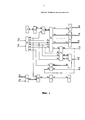
Сущность изобретения поясняется чертежами, где на фиг. 1 - представлена структурная схема системы, на фиг. 2 - структурная схема блока селекции отчетов спектральных диапазонов частот, на фиг. 3 - структурная схема блока синхронизации работы системы, на фиг. 4 - структурная схема блока селекции опорных адресов записей диапазонов частот, на фиг. 5 - структурная схема блока идентификации временных интервалов обработки отчетов.The invention is illustrated by drawings, where in FIG. 1 is a structural diagram of a system; FIG. 2 is a block diagram of a selection block of reports of spectral frequency ranges, FIG. 3 is a block diagram of a system synchronization unit; FIG. 4 is a block diagram of a selection block of reference addresses of frequency band records, FIG. 5 is a structural diagram of a unit for identifying time intervals for processing reports.
Система (фиг. 1) содержит блок 1 регистрации звука, первый усилитель 2, аналого-цифровой преобразователь 3, блок 4 селекции отчетов спектральных диапазонов частот, цифровые фильтры 5-7 группы, блок 8 синхронизации работы системы, блок 9 селекции опорных адресов записей диапазонов частот, блок 10 идентификации временных интервалов обработки отчетов, блок 11 адресации текущих записей отчетов, блок 12 приема сигнала свертки, цифроаналоговый 13 преобразователь, второй 14 усилитель и блок 15 воспроизведения.The system (Fig. 1) contains a
На фиг. 1 показаны управляющий 20, установочный 21, информационный 22 и синхронизирующий 23 входы системы, а также адресный 24, информационные 25-27 выходы группы системы, первый 28 и второй 29 синхронизирующие выходы системы.In FIG. 1 shows the
Блок 1 (фиг. 1) регистрации звука выполнен в виде микрофона, имеющего выход 30.Block 1 (Fig. 1) of sound recording is made in the form of a microphone having an output 30.
Первый усилитель 2 (фиг. 1) имеет вход 31 и выход 32.The first amplifier 2 (Fig. 1) has an input 31 and an
Аналого-цифровой преобразователь 3 (фиг. 1) имеет сигнальный 33 и синхронизирующий 34 входы, а также информационный выход 35.The analog-to-digital Converter 3 (Fig. 1) has a
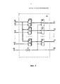
Блок 4 (фиг. 2) селекции отчетов спектральных диапазонов частот содержит регистры 75-77, группы элементов 78-80 И, а также элемент 81 задержки. На чертеже показаны информационный 36, синхронизирующий 37 входы, и группа 38-40 управляющих входов, а также группа 41-43 информационных и синхронизирующий 44 выходы.Block 4 (Fig. 2) of selection of reports of spectral frequency ranges contains registers 75-77, groups of elements 78-80 And, as well as
Цифровые фильтры 5-7 (фиг. 1) имеют информационные входы 45-47 и информационные выходы 25-27 соответственно.Digital filters 5-7 (Fig. 1) have information inputs 45-47 and information outputs 25-27, respectively.
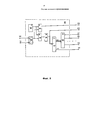
Блок 8 (фиг. 3) синхронизации работы системы содержит генератор импульсов 82, триггер 83, элементы 84, 85 И, делитель частоты 86, счетчик 87 и дешифратор 88. На чертеже показаны управляющий 20 и установочный 21 входы, а также первый 48 и второй 49 тактирующие выходы, группа 51-53 управляющих, и синхронизирующий 50 выходы.Block 8 (Fig. 3) of the synchronization system includes a
Блок 9 (фиг. 4) селекции опорных адресов записей диапазонов частот содержит постоянное запоминающее устройство 89, регистр 90, элементы 91-93 И, элементы 94-96 задержки. На чертеже показаны синхронизирующий 54 вход, группа управляющих входов 55-57, а также информационный 58, первый 59 и второй 60 синхронизирующие выходы.Block 9 (Fig. 4) selection of reference addresses of records of frequency ranges contains a read-
Блок 10 (фиг. 5) идентификации временных интервалов обработки отчетов содержит счетчик 97, регистр 98, и компаратор 99. На чертеже показаны счетный 61 и синхронизирующий 62 входы, а также информационный 63 и синхронизирующий 64 выходы.Block 10 (Fig. 5) of identification of time intervals for processing reports includes a
Блок 11 (фиг. 1) адресации текущих записей отчетов выполнен в виде сумматора, имеющего информационные 65-66, и синхронизирующий входы, а также адресный 24 выход, являющийся адресным выходом системы.Block 11 (Fig. 1) addressing the current records of reports is made in the form of an adder having information 65-66, and synchronizing inputs, as well as
Блок 12 (фиг. 1) приема цифровых сигналов свертки выполнен в виде регистра, имеющего информационный вход 22, синхронизирующий вход 23, а также информационный выход 105.Block 12 (Fig. 1) of receiving digital convolution signals is made in the form of a register having an
Цифроаналоговый преобразователь 13 (фиг. 1) имеет информационный 106 и тактирующий 107 входы, а также сигнальный выход 108.The digital-to-analog converter 13 (Fig. 1) has information 106 and
Второй усилитель 14 (фиг. 1) имеет сигнальный вход 109 и сигнальный выход 110.The second amplifier 14 (Fig. 1) has a
Блок 15 воспроизведения (фиг. 1) выполнен в виде динамика, имеющего сигнальный вход 111.The playback unit 15 (Fig. 1) is made in the form of a speaker having a signal input 111.
Все узлы и элементы системы выполнены на стандартных потенциально-импульсных элементах.All nodes and elements of the system are made on standard potential-impulse elements.
Система работает следующим образом.The system operates as follows.
Запуск системы осуществляется подачей на управляющий вход 20 блока 8 синхронизации сигнала, который, поступая на единичный вход триггера 83 блока 8, устанавливает последний в единичное состояние. При этом высоким потенциалом с прямого выхода триггера 83 будут открыты по одному входу элементы 84 и 85 И. В результате тактирующие импульсы с выхода генератора 82 импульсов проходят через элемент 84 на первый 48 тактирующий выход блока 8 и далее поступают на синхронизирующий вход 34 аналого-цифрового преобразователя 3.The system is launched by applying to the
Параллельно с этим, акустический шум звукового диапазона (от 15 до 25000 Гц) улавливается блоком 1, и с выхода 30 блока 1 поступает на вход 31 усилителя 2. После усиления акустический шум с выхода 32 усилителя 2 поступает на сигнальный вход 33 цифроаналогового преобразователя, где и преобразуется в цифровой код, который с выхода 35 цифроаналогового преобразователя поступает на информационный 36 вход блока 4, осуществляющего селекцию отчетов спектральных диапазонов частот акустического шума под управлением блока 8.In parallel, the acoustic noise of the sound range (from 15 to 25000 Hz) is captured by
Блок 4 содержит n-каналов отчетов спектральных диапазонов частот акустического шума (так называемых семплов), каждый из которых состоит из элементов И группы и регистра. На фиг. 2 для примера показаны первый канал, представленный элементами 78 И группы и регистром 75, второй канал, представленный элементами 79 И группы и регистром 76, и третий канал, представленный элементами 80 И группы и регистром 77. В опытном образце системы блок 4 содержит 12- каналов отчетов спектральных диапазонов частот акустического шума.
Информационные выходы 41-43 каждого из регистров 75-77 блока 4 подключены к информационным входам 45-47 соответствующих цифровых фильтров 5-7, каждый из которых настроен на определенный спектральный диапазон (выбор спектральных окон осуществляется в диапазоне 0-15 кГц). По существу, в опытном образце системы совокупность цифровых фильтров 5-7 представляет собой 12-ти канальный цифровой фильтр, каждый канал которого настроен на определенный спектральный диапазон.The information outputs 41-43 of each of the registers 75-77 of
Для управления работой системы, в блоке 8 тактирующие импульсы генератора 82 с выхода элемента 85 И поступают на делитель частоты 86, с выхода которого они, во-первых, поступают на счетный вход счетчика 87, который предназначен для подсчета числа отчетов спектральных диапазонов частот акустического шума, которые должны быть выполнены блоком 4, а, во-вторых, через выход 49 блока 8 они выдаются на тактирующий вход 37 блока 4.To control the operation of the system, in
Код показаний числа отчетов счетчика 87 поступает на вход дешифратора 88, который, расшифровывая показания счетчика 87, последовательно формирует высокие разрешающие потенциалы на своих управляющих выходах 51-53 соответственно.The code of the readings of the number of reports of the
В результате этого, например, как только счетчик 87 блока 8 зафиксирует первый импульс, на выходе 51 дешифратора 88 появится высокий потенциал, который через вход 38 блока 4 откроет элементы 78 И по одному входу, на другой вход которых поступает цифровой код акустического шума с входа 36 блока 4.As a result of this, for example, as soon as the
Цифровой код акустического шума с входа 36 блока 4 проходит через открытые элементы 78 И группы на информационный вход регистра 75, и заносится в него тактирующим импульсом с входа 37 блока 8, задержанным элементом 81 задержки на время срабатывания счетчика 87 и дешифратора 88 блока 8. Кроме того, тактирующий импульс с выхода элемента 81 задержки через выход 44 блока 4 выдается на вход 54 блока 9.The digital code of acoustic noise from the
Параллельно с описанным процессом формирования первого отчета спектральных диапазонов частот акустического шума, управляющий потенциал с выхода 51 блока 8 через вход 55 блока 9 поступает на один вход элемента 91 И, на другой вход которого с входа 54 блока 9 поступает тактирующий импульс. Тактирующий импульс проходит через элемент 91 И на вход считывания фиксированной ячейки памяти постоянного запоминающего устройства 89, в которой записан опорный адрес зоны памяти сервера базы данных, выделенной для записи всех отчетов спектральных диапазонов частот акустического шума, например, первого из 12-ти каналов.In parallel with the described process of generating the first report of the spectral frequency ranges of acoustic noise, the control potential from the
Код опорного адреса с выхода постоянного запоминающего устройства считывается на информационный вход регистра 90 и заносится в него синхронизирующим импульсом с входа 54 блока 9, задержанным элементом 94 на время срабатывания постоянного запоминающего устройства 89.The reference address code from the output of the read-only memory is read to the information input of the
Код опорного адреса с выхода 58 блока 9 поступает на один 65 информационный вход сумматора 11, на другой информационный вход 66 которого поступает код с выхода 63 блока 10. По синхронизирующему сигналу с выхода 59 блока 9, поступающему на синхронизирующий вход 67, сумматор 11 суммирует входные коды и на адресном выходе 24 системы формирует итоговый адрес записи отчета спектральных диапазонов частот акустического шума с соответствующего информационного выхода 25-27 системы.The reference address code from the
Кроме того, синхронизирующий импульс с выхода элемента 95 задержки дополнительно задерживается элементом 96 на время формирования итогового адреса на выходе блока 11, и затем через синхронизирующий выход 28 системы выдается на первый канал прерывания сервера базы данных. По этому сигналу сервер базы данных переходит на программу записи отчета спектральных диапазонов частот акустического шума с соответствующего информационного выхода 25-27 системы по указанному на выходе 24 адресу.In addition, the synchronizing pulse from the output of the
Логика работы системы реализуется с помощью счетчика 87 блока 8, который настраивается на требуемую частоту дискретизации входного акустического сигнала (32 кГц, 44 кГц и т.д.). При переполнении счетчика 87 блока 8 на его выходе 115 формируется импульс переноса, который через выход 50 блока 8 поступает на счетный вход счетчика 97 блока 10, фиксируя факт окончания записи в сервер базы данных, первого массива данных, например, из 12-ти семплов.The logic of the system is implemented using the
В регистр 98 блока 10 заранее перед началом работы системы заносится константа - задается число массивов семплов, достаточное для того, чтобы система смогла начать процедуру обработки полученных и записанных в память сервера базы данных. Код константы с выхода регистра 98 поступает на один вход 101 компаратора 99, на другой вход 100 которого поступает текущее значение количества сформированных массивов семплов.A constant is entered into the
Каждый раз с окончанием очередной процедуры записи очередного семпла в память сервера базы данных, синхронизирующий импульс с выхода 60 блока 9 через вход 62 блока 10 поступает на синхронизирующий вход компаратора 99, который сравнивает код константы регистра 98 с текущим значением кода счетчика 97. Как только показания счетчика 97 будут больше или равны численному значению константы, на выходе 103 компаратора 99 формируется сигнал, который с выхода 64 блока 10 поступает на вход второго канала прерывания сервера базы данных.Each time after the end of the next recording procedure of the next sample in the memory of the database server, the synchronizing pulse from the
По этому сигналу сервер базы данных переходит на подпрограмму чтения массивов данных, соответствующих каждому из спектральных окон и последовательно запускает алгоритмы прогнозирования фазы и амплитуды сигналов (по очереди для каждого окна). По окончании анализа управление передается программному модулю, осуществляющему свертку всех спектральных окон в единый сигнал, который с выхода сервера базы данных через информационный вход 22 системы выдается на информационный вход блока 12 и заносится в него синхронизирующим импульсом, поступающим с входа 23 системы.By this signal, the database server switches to the subroutine for reading the data arrays corresponding to each of the spectral windows and sequentially runs the algorithms for predicting the phase and amplitude of the signals (in turn for each window). At the end of the analysis, control is transferred to a software module that convolves all spectral windows into a single signal, which from the output of the database server through the
С выхода 105 блока 12 цифровой сигнал поступает на информационный вход цифроаналогового преобразователя 13, где преобразуется в широкополосный аналоговый сигнал, который с выхода 108 цифроаналогового преобразователя 13 через вход 109 поступает на широкополосный усилитель 14, где он усиливается до необходимого уровня и далее с выхода 110 усилителя 14 поступает на вход 111 блока воспроизведения.From the
Таким образом, введение новых блоков и новых конструктивных связей позволило существенно повысить надежность шумоподавления во всем диапазоне звуковых частот в заданном объеме путем интеллектуальной обработки шума в режиме реального времени, позволяющей осуществлять генерацию сигнала антишума, компенсируя задержки в цепях обработки и приема и излучения сигнала антишума.Thus, the introduction of new blocks and new constructive connections made it possible to significantly increase the noise reduction reliability over the entire range of sound frequencies in a given volume by real-time intelligent noise processing, which allows generating an anti-noise signal, compensating for delays in the processing and reception and emission chains of the anti-noise signal.
Источники информации, принятые во внимание при составлении описания заявки:Sources of information taken into account when drawing up the description of the application:
1. Патент РФ №2411592 (10.02.2011)1. RF patent No. 2411592 (02/10/2011)
2. Патент РФ №2545462 (24.06.2013) (прототип).2. RF patent No. 2545462 (06.24.2013) (prototype).
Claims (1)
Priority Applications (1)
| Application Number | Priority Date | Filing Date | Title |
|---|---|---|---|
| RU2017116204U RU179556U1 (en) | 2017-05-11 | 2017-05-11 | Active noise reduction system |
Applications Claiming Priority (1)
| Application Number | Priority Date | Filing Date | Title |
|---|---|---|---|
| RU2017116204U RU179556U1 (en) | 2017-05-11 | 2017-05-11 | Active noise reduction system |
Publications (1)
| Publication Number | Publication Date |
|---|---|
| RU179556U1 true RU179556U1 (en) | 2018-05-17 |
Family
ID=62151918
Family Applications (1)
| Application Number | Title | Priority Date | Filing Date |
|---|---|---|---|
| RU2017116204U RU179556U1 (en) | 2017-05-11 | 2017-05-11 | Active noise reduction system |
Country Status (1)
| Country | Link |
|---|---|
| RU (1) | RU179556U1 (en) |
Citations (5)
| Publication number | Priority date | Publication date | Assignee | Title |
|---|---|---|---|---|
| US5899977A (en) * | 1996-07-08 | 1999-05-04 | Sony Corporation | Acoustic signal processing apparatus wherein pre-set acoustic characteristics are added to input voice signals |
| RU77065U1 (en) * | 2008-06-05 | 2008-10-10 | Федеральное государственное унитарное предприятие "Научно-исследовательский институт "Восход" | AUTOMATED SYSTEM OF EVALUATION AND CONTROL OF PROFESSIONAL RISKS IN THE FIELD OF LABOR RELATIONS |
| RU91200U1 (en) * | 2009-10-19 | 2010-01-27 | Федеральное государственное унитарное предприятие "Научно-исследовательский институт "Восход" | SYSTEM OF INFORMATION INTERACTION OF THE PORTAL OF THE ALL-RUSSIAN STATE INFORMATION CENTER WITH SUPPLIERS AT STATE PURCHASES |
| RU2545462C2 (en) * | 2013-06-24 | 2015-03-27 | Общество с ограниченной ответственностью "Новые Акустические Системы" | System for active noise reduction with ultrasonic radiator |
| EP2800091B1 (en) * | 2009-04-28 | 2016-01-20 | Bose Corporation | Sound-dependent ANR signal processing adjustment |
-
2017
- 2017-05-11 RU RU2017116204U patent/RU179556U1/en not_active IP Right Cessation
Patent Citations (5)
| Publication number | Priority date | Publication date | Assignee | Title |
|---|---|---|---|---|
| US5899977A (en) * | 1996-07-08 | 1999-05-04 | Sony Corporation | Acoustic signal processing apparatus wherein pre-set acoustic characteristics are added to input voice signals |
| RU77065U1 (en) * | 2008-06-05 | 2008-10-10 | Федеральное государственное унитарное предприятие "Научно-исследовательский институт "Восход" | AUTOMATED SYSTEM OF EVALUATION AND CONTROL OF PROFESSIONAL RISKS IN THE FIELD OF LABOR RELATIONS |
| EP2800091B1 (en) * | 2009-04-28 | 2016-01-20 | Bose Corporation | Sound-dependent ANR signal processing adjustment |
| RU91200U1 (en) * | 2009-10-19 | 2010-01-27 | Федеральное государственное унитарное предприятие "Научно-исследовательский институт "Восход" | SYSTEM OF INFORMATION INTERACTION OF THE PORTAL OF THE ALL-RUSSIAN STATE INFORMATION CENTER WITH SUPPLIERS AT STATE PURCHASES |
| RU2545462C2 (en) * | 2013-06-24 | 2015-03-27 | Общество с ограниченной ответственностью "Новые Акустические Системы" | System for active noise reduction with ultrasonic radiator |
Similar Documents
| Publication | Publication Date | Title |
|---|---|---|
| CA1278086C (en) | Sound location arrangement | |
| RU2019124543A (en) | SOUND RECORDING USING DIRECTIONAL DIAGRAM FORMATION | |
| CN112509595A (en) | Audio data processing method, system and storage medium | |
| Tohyama | Waveform Analysis of Sound | |
| CN109800724B (en) | Loudspeaker position determining method, device, terminal and storage medium | |
| CN105103219A (en) | Noise reduction method | |
| RU179556U1 (en) | Active noise reduction system | |
| EP0380310B1 (en) | An acoustic analysis device and a frequency conversion device used therefor | |
| US3270833A (en) | Method of and apparatus for measuring ensemble averages and decay curves | |
| WO2023025081A1 (en) | Double-sided two-way ranging protocol based on composite, ultrasonic tones | |
| Clifford et al. | Using delay estimation to reduce comb filtering of arbitrary musical sources | |
| AU1768700A (en) | Flat surface loudspeaker and method for operating the same | |
| CN109246573A (en) | Measure the method and device of audio system Frequency Response | |
| TW201506915A (en) | Method and device for extracting single audio source from multiple audio sources within space | |
| JP3690332B2 (en) | Radar jamming device | |
| Misono et al. | Frequency characteristics of the A-weighted sound pressure level of robust cicada climax sound | |
| Muron et al. | Modelling of reverberations and audioconference rooms | |
| US11812230B2 (en) | Measurement method and measurement apparatus | |
| US11483644B1 (en) | Filtering early reflections | |
| US3352378A (en) | Apparatus for and method of determining the acoustical reverberation time of an enclosure | |
| SU739579A2 (en) | Graphical data readout device | |
| JPS58156997A (en) | Active type silencer | |
| JPH01212381A (en) | Sonar | |
| KR970004178B1 (en) | Audio echo sound adding device | |
| SU1128160A1 (en) | Device for registering ultrasonic signals |
Legal Events
| Date | Code | Title | Description |
|---|---|---|---|
| MM9K | Utility model has become invalid (non-payment of fees) |
Effective date: 20180112 |