RU178012U1 - Nasal Aspirator - Google Patents
Nasal Aspirator Download PDFInfo
- Publication number
- RU178012U1 RU178012U1 RU2017128547U RU2017128547U RU178012U1 RU 178012 U1 RU178012 U1 RU 178012U1 RU 2017128547 U RU2017128547 U RU 2017128547U RU 2017128547 U RU2017128547 U RU 2017128547U RU 178012 U1 RU178012 U1 RU 178012U1
- Authority
- RU
- Russia
- Prior art keywords
- contents
- aspirator
- scrubbed
- negative pressure
- hole
- Prior art date
Links
Images

Classifications
-
- A—HUMAN NECESSITIES
- A61—MEDICAL OR VETERINARY SCIENCE; HYGIENE
- A61M—DEVICES FOR INTRODUCING MEDIA INTO, OR ONTO, THE BODY; DEVICES FOR TRANSDUCING BODY MEDIA OR FOR TAKING MEDIA FROM THE BODY; DEVICES FOR PRODUCING OR ENDING SLEEP OR STUPOR
- A61M15/00—Inhalators
- A61M15/08—Inhaling devices inserted into the nose
Abstract
Предлагаемая полезная модель относится к устройствам для очищения верхних дыхательных путей и раскрывает конструкцию назального аспиратора, содержащего корпус, содержащий проксимальную часть, внутренний объем которой разделен перегородкой на первую часть и вторую часть, имеющую отверстие для принятия вычищаемого содержимого, и выполненную с возможностью разъёмного соединения с проксимальной частью дистальную часть, содержащую внутренний канал, соединенный с отверстием для присоединения к источнику отрицательного давления, причем при соединении проксимальной части и дистальной части корпуса канал входит в первую часть корпуса с заведением его конца за край перегородки и с обеспечением сообщения этого канала (7) со второй частью (2) корпуса. Помимо расширения арсенала технических средств, предлагаемая конструкция назального аспиратора обеспечивает уменьшение загрязнения внутренней полости корпуса аспиратора очищенным содержимым, в частности более надежное предотвращение попадания очищаемого содержимого в область отверстия для соединения с источником отрицательного давления, без использования сменных элементов (например, фильтров).The proposed utility model relates to devices for cleaning the upper respiratory tract and discloses the design of a nasal aspirator containing a body containing a proximal part, the internal volume of which is divided by a partition into the first part and the second part having an opening for receiving the scrubbed contents, and made with the possibility of detachable connection with the proximal part of the distal part containing an internal channel connected to the hole for connection to a source of negative pressure, and when connecting the proximal part and the distal part of the body, the channel enters the first part of the body with the institution of its end beyond the edge of the septum and ensuring communication of this channel (7) with the second part (2) of the body. In addition to expanding the arsenal of technical means, the proposed design of the nasal aspirator reduces the contamination of the inner cavity of the aspirator body with cleaned contents, in particular, more reliably prevents the cleaned contents from getting into the area of the hole for connection with a negative pressure source, without the use of replaceable elements (e.g. filters).
Description
ОБЛАСТЬ ТЕХНИКИFIELD OF TECHNOLOGY
[0001] Предлагаемая полезная модель относится к устройствам для очищения верхних дыхательных путей, в частности носовых ходов у детей, в особенности детей младшего дошкольного возраста, и может быть использовано как вручную с приложением отрицательного давления другим человеком, так и совместно с вакуумным устройством, создающим отрицательное давление. [0001] The proposed utility model relates to devices for cleansing the upper respiratory tract, in particular the nasal passages in children, in particular children of preschool age, and can be used either manually with the application of negative pressure by another person, or in conjunction with a vacuum device that creates negative pressure.
УРОВЕНЬ ТЕХНИКИBACKGROUND
[0002] Некоторые люди не способны или не имеют возможности самостоятельно прочищать верхние дыхательные пути с помощью сморкания. Например, дети, в особенности дети младшего дошкольного возраста, не умеют сморкаться и научаются это делать лишь к более сознательному возрасту. Тем временем, изменение качества и количества слизистых выделений в носовых ходах является практически первой и очень важной физиологической реакцией здорового организма на появление в верхних дыхательных путях патогенных микроорганизмов или попадание вирусов, в связи с чем регулярное очищение верхних дыхательных путей от выделений в таких ситуациях является важным для поддержания нормальной микрофлоры верхних дыхательных путей и общего состояния иммунитета. [0002] Some people are unable or unable to independently clear their upper airways by blowing their nose. For example, children, especially children of primary preschool age, do not know how to blow their nose and learn to do this only to a more conscious age. Meanwhile, a change in the quality and quantity of mucous secretions in the nasal passages is practically the first and very important physiological reaction of a healthy organism to the appearance of pathogenic microorganisms in the upper respiratory tract or the entry of viruses, and therefore regular cleaning of the upper respiratory tract from secretions is important in such situations to maintain normal microflora of the upper respiratory tract and the general state of immunity.
[0003] Из уровня техники известен аспиратор, раскрытый в WO03035144 (A1) (опубл. 01.05.2003), содержащий разъемный корпус, состоящий из проксимальной части, которая содержит отверстие для принятия вычищаемого содержимого, и дистальной части, содержащей отверстие для присоединения к источнику отрицательного давления. При этом в проксимальной части известного аспиратора предусмотрен фильтр, который расположен с обеспечением полного перекрытия полости корпуса перпендикулярно потоку воздуха из отверстия для принятия вычищаемого содержимого и, таким образом, препятствует попаданию вычищаемого содержимого в область отверстия для присоединения к источнику отрицательного давления. Такая конструкция надежно защищает дистальную часть и, в частности, отверстие для присоединения к источнику отрицательного давления от загрязнения вычищаемым содержимым. Однако по мере загрязнения фильтра эффективность использования устройство сильно снижается и для его использования по назначению требуется замена фильтра. [0003] An aspirator is disclosed in the prior art, disclosed in WO03035144 (A1) (publ. 05/01/2003) comprising a detachable housing consisting of a proximal portion that includes an opening for receiving scrubbed contents, and a distal portion containing an opening for attaching to the source negative pressure. At the same time, a filter is provided in the proximal part of the known aspirator, which is located so as to completely overlap the body cavity perpendicular to the air flow from the hole for receiving the scrubbed contents and, thus, prevents the scrubbed contents from entering the region of the hole for connection to a negative pressure source. This design reliably protects the distal part and, in particular, the hole for attaching to the source of negative pressure from contamination by the contents to be cleaned. However, as the filter becomes dirty, the efficiency of use of the device is greatly reduced, and for its intended use, the filter must be replaced.
[0004] Для соблюдения гигиены имеющиеся на рынке аналоги известного устройства, например аспиратор «Отривин» от Novartis, предполагают замену всей проксимальной части корпуса, включая фильтр. Такое решение эффективно решает проблему гигиеничности повторного использования устройства, но сопряжено с необходимостью использования относительно большой по размеру расходной части, что, в частности, значительно повышает стоимость изделия для пользователя. [0004] To maintain good hygiene, commercially available analogues of the known device, such as the Novartis Otrivin Suction Pump, suggest replacing the entire proximal portion of the housing, including the filter. Such a solution effectively solves the hygiene problem of reuse of the device, but involves the need to use a relatively large consumable, which, in particular, significantly increases the cost of the product for the user.
[0005] Из уровня техники известны и такие конструкции аспираторов, которые не содержат фильтров. Например, аспиратор Pigeon (http://www.akusherstvo.ru/magaz.php?action=show_tovar&tovar_id=34723), выбранный в качестве наиболее близкого аналога предлагаемой полезной модели и имеющий разъемный корпус, состоящий из проксимальной части, которая содержит отверстие для принятия вычищаемого содержимого, соединенный с ним канал для отвода вычищаемого содержимого, а также отверстие для присоединения к источнику отрицательного давления, и дистальной части, содержащей камеру для сбора вычищаемого содержимого, причем проксимальная часть и дистальная часть корпуса имеют такую конструкцию, что при их соединении канал для отвода вычищаемого содержимого входит в камеру для сбора вычищаемого содержимого. Поддерживать гигиену такого аспиратора возможно путём промывания частей корпуса, которое облегчено за счет того, что корпус выполнен разъемным. Предотвращение попадания вычищаемого содержимого в область отверстия для присоединения к источнику отрицательного давления обеспечивается за счет наличия специального канала для отвода вычищаемого содержимого, соединенного с отверстием для принятия этого содержимого, и обеспечения входа этого канала в камеру для сбора вычищаемого содержимого при соединении частей корпуса. Тем не менее при соединении проксимальной и дистальной частей корпуса (когда аспиратор в сборе) выход указанного канала и отверстие для присоединения к источнику отрицательного давления оказываются в одной и той же полости канала и никак не разделены, из-за чего есть вероятность попадания накопленного в камере содержимого в область отверстия для присоединения к источнику отрицательного давления. Например, при использовании аспиратора возможны непроизвольные движения и повороты устройства, в результате чего под действием силы тяжести накопленное в камере содержимое может переместиться в область отверстия для присоединения к источнику отрицательного давления. При этом попадание вычищаемого содержимого в эту область существенно повышает вероятность загрязнения соединительных элементов между аспиратором и источником отрицательного давления, а также нарушению работы аспиратора в целом, так как указанные соединительные элементы являются относительно узкими и могут засориться при попадании в них вычищенного содержимого. Среди недостатков известного аспиратора можно отметить и не вполне эргономичную форму корпуса, которая при резких движениях, характерных, например, для маленьких детей, может нарушить удобство и атравматичность использования устройства. Немаловажным фактором является и сложность формы корпуса, производство которого ожидаемо более сложное, чем изготовление корпусов более простой и технологичной формы. [0005] Such aspirator designs that do not contain filters are also known in the art. For example, the Pigeon aspirator (http://www.akusherstvo.ru/magaz.php?action=show_tovar&tovar_id=34723), selected as the closest analogue of the proposed utility model and having a detachable body consisting of a proximal part that contains a hole for acceptance the contents to be scrubbed, a channel for removing the contents to be scrubbed, and an opening for connecting to a negative pressure source, and a distal portion containing a chamber for collecting the contents to be scrubbed, the proximal portion and the distal portion of the body having the design that when they are connected, the channel for removal of the contents to be scrubbed enters the chamber for collecting the contents to be scrubbed. It is possible to maintain hygiene of such an aspirator by washing parts of the housing, which is facilitated by the fact that the housing is detachable. Prevention of the scrubbed contents from entering the area of the hole for connection to a negative pressure source is provided by the presence of a special channel for removing the scrubbed contents connected to the hole for receiving this content, and by allowing this channel to enter the chamber for collecting the scrubbed contents when connecting parts of the housing. Nevertheless, when connecting the proximal and distal parts of the body (when the aspirator is assembled), the outlet of the indicated channel and the hole for connection to the source of negative pressure appear in the same cavity of the channel and are not separated in any way, because of which there is a chance of the accumulation in the chamber contents in the area of the hole for attachment to a source of negative pressure. For example, when using an aspirator, involuntary movements and rotations of the device are possible, as a result of which, under the action of gravity, the contents accumulated in the chamber can move to the region of the hole for attachment to a source of negative pressure. At the same time, getting the scrubbed contents into this area significantly increases the likelihood of contamination of the connecting elements between the aspirator and the source of negative pressure, as well as disrupting the operation of the aspirator as a whole, since these connecting elements are relatively narrow and can become clogged when the scrubbed contents get into them. Among the shortcomings of the known aspirator, one can also note the not quite ergonomic shape of the case, which, with sudden movements, typical, for example, for small children, can disrupt the convenience and non-invasiveness of using the device. An important factor is the complexity of the shape of the case, the production of which is expected to be more complicated than the manufacture of cases of a simpler and more technologically advanced form.
[0006] Таким образом, настоящая полезная модель направлена на решение технической проблемы предотвращения попадания вычищаемого аспиратором содержимого в область отверстия для присоединения к источнику отрицательного давления. Помимо этого, существует необходимость в назальном аспираторе для очищения верхних дыхательных путей, который был бы несложен в производстве, легким и недорогим в обслуживании (в частности, при санитарно-гигиеническом обслуживании).[0006] Thus, the present utility model addresses the technical problem of preventing the contents of the aspirator being cleaned from entering the area of the hole for attachment to a negative pressure source. In addition, there is a need for a nasal aspirator for cleansing the upper respiratory tract, which would be simple to manufacture, easy and inexpensive to maintain (in particular, for sanitary and hygienic maintenance).
РАСКРЫТИЕ СУЩНОСТИ ПОЛЕЗНОЙ МОДЕЛИDISCLOSURE OF THE ESSENCE OF A USEFUL MODEL
[0007] Согласно настоящей полезной модели предложен назальный аспиратор для очищения верхних дыхательных путей, содержащий корпус, содержащий проксимальную часть, внутренний объем которой разделен перегородкой на первую часть и вторую часть, имеющую отверстие для принятия вычищаемого содержимого, и выполненную с возможностью разъёмного соединения с проксимальной частью дистальную часть, содержащую внутренний канал, соединенный с отверстием для присоединения к источнику отрицательного давления, причем при соединении проксимальной части и дистальной части корпуса канал входит в первую часть корпуса с заведением его конца за край перегородки и с обеспечением сообщения этого канала со второй частью корпуса. [0007] According to this utility model, a nasal aspirator for cleansing the upper respiratory tract is provided, comprising a body containing a proximal part, the inner volume of which is divided by a septum into a first part and a second part having an opening for receiving scrubbed contents, and configured to detachably connect to the proximal part of the distal part containing an internal channel connected to the hole for connection to a source of negative pressure, and when connecting the proximal hour The channel and the distal part of the housing enter the first part of the housing with the institution of its end beyond the edge of the partition and with the communication of this channel with the second part of the housing.
[0008] Предлагаемая конструкция назального аспиратора обеспечивает технический результат в виде уменьшения загрязнения внутренней полости корпуса аспиратора вычищаемым содержимым, в частности более надежное предотвращение попадания вычищаемого содержимого в область отверстия для соединения с источником отрицательного давления, без использования сменных элементов (например, фильтров) благодаря тому, что предлагаемый аспиратор имеет корпус, содержащий проксимальную часть, внутренний объем которой разделен перегородкой на первую часть и вторую часть, имеющую отверстие для принятия вычищаемого содержимого, и выполненную с возможностью разъёмного соединения с проксимальной частью дистальную часть, содержащую внутренний канал, соединенный с отверстием для присоединения к источнику отрицательного давления, причем при соединении проксимальной части и дистальной части корпуса канал входит в первую часть корпуса с заведением его конца за край перегородки и с обеспечением сообщения этого канала со второй частью корпуса. Расположение отверстия для принятия вычищаемого содержимого в проксимальной части, а отверстия для присоединения к источнику отрицательного давления в дистальной части обеспечивает пространственное разнесение указанных отверстий и их удаление друг от друга. При этом особое значение имеет то, что внутренний объем проксимальной части разделен перегородкой на первую часть и вторую часть, а в аспираторе в сборе отверстие для принятия вычищаемого содержимого и канал, соединенный с отверстием для присоединения к источнику отрицательного давления, оказываются в различных частях проксимальной части. Такие особенности конструкции позволяют предотвратить попадание вычищаемого содержимого в область отверстия для присоединения к источнику отрицательного давления, не прибегая к использованию каких-либо фильтрующих вычищенное содержимое элементов. [0008] The proposed design of the nasal aspirator provides a technical result in the form of reducing contamination of the inner cavity of the aspirator body with the scrubbed contents, in particular, more reliably preventing the scrubbed contents from entering the area of the hole for connection with a negative pressure source, without the use of replaceable elements (eg filters) that the proposed aspirator has a housing containing a proximal part, the internal volume of which is divided by a partition into the first part l and the second part, having an opening for receiving the scrubbed contents, and made with the possibility of detachable connection with the proximal part of the distal part, containing an internal channel connected to the hole for connection to a source of negative pressure, and when connecting the proximal part and the distal part of the body, the channel enters the first part of the housing with the institution of its end beyond the edge of the partition and providing communication of this channel with the second part of the housing. The location of the holes for receiving the scrubbed contents in the proximal part, and the holes for attaching to the source of negative pressure in the distal part provides spatial diversity of these holes and their removal from each other. Of particular importance is the fact that the internal volume of the proximal part is divided by a partition into the first part and the second part, and in the aspirator assembly, the hole for receiving the contents to be scrubbed and the channel connected to the hole for connection to the negative pressure source are in different parts of the proximal part . Such design features make it possible to prevent the scrubbed contents from entering the region of the hole for attachment to a source of negative pressure without resorting to using any filtering scrubbed content elements.
[0009] Кроме того, предлагаемая конструкция обеспечивает облегчение санитарно-гигиенического обслуживания аспиратора, а также является более простой и эффективной при производстве и использовании, чем известные заявителю аналоги. Указанные преимущества достижимы благодаря простой форме конструкции и её внутренних полостей, которые оказываются легко доступны после разборки корпуса на проксимальную и дистальную части, благодаря чему внутренние поверхности полости корпуса могут быть без затруднения промыты водой или стерилизующим раствором. Отсутствие необходимости замены каких-либо фильтрующих или загрязняющихся элементов делает аспиратор более простым в производстве и использовании, а возможность оперативного санитарно-гигиенического обслуживания после каждого применения повышает гигиеничность устройства. [0009] In addition, the proposed design provides easier sanitary and hygienic maintenance of the aspirator, and is also simpler and more efficient in production and use than the analogues known to the applicant. These advantages are achievable due to the simple form of the structure and its internal cavities, which are easily accessible after disassembling the body into the proximal and distal parts, so that the internal surfaces of the body cavity can be washed without difficulty with water or a sterilizing solution. The absence of the need to replace any filtering or contaminating elements makes the aspirator easier to manufacture and use, and the possibility of prompt sanitary and hygienic maintenance after each use increases the hygiene of the device.
[00010] Согласно некоторым из вариантов реализации предлагаемой полезной модели, область проксимальной части корпуса, в которой находится отверстие для принятия вычищаемого содержимого, выполнена конусоподобной формы, формы выпуклого тела вращения и/или округлой вытянутой формы, обеспечивающей возможность вставлять указанную область в носовой проход. Согласно некоторым вариантам реализации, по меньшей мере область проксимальной части, в которой находится отверстие для принятия вычищаемого содержимого, выполнена из эластичного материала. Указанные особенности обеспечивают атравматичность использования устройства. [00010] According to some of the embodiments of the proposed utility model, the area of the proximal part of the body in which the hole for receiving the scrubbed contents is located is made conical in shape, in the shape of a convex body of revolution and / or in a round elongated shape, which makes it possible to insert the specified area into the nasal passage. According to some embodiments, at least the region of the proximal portion in which the opening for receiving the scrubbed contents is located is made of elastic material. These features provide non-invasive use of the device.
[00011] Согласно некоторым вариантам реализации, аспиратор содержит эластичную трубку, выполненную с возможностью присоединения к отверстию для присоединения к источнику отрицательного давления. Указанные признаки облегчают использование аспиратора с источником отрицательного давления благодаря тому, что эластичная трубка может быть легко соединена, например, со штуцером микрокомпрессора, при этом обеспечена большая свобода в размещении аспиратора. [00011] According to some embodiments, the aspirator comprises an elastic tube configured to attach to a hole for connection to a negative pressure source. These features facilitate the use of an aspirator with a source of negative pressure due to the fact that the elastic tube can be easily connected, for example, to the fitting of the microcompressor, while providing greater freedom in the placement of the aspirator.
[00012] Согласно некоторым вариантам реализации, аспиратор также содержит мундштук, выполненный с возможностью присоединения к эластичной трубке. Таким образом, в качестве источника отрицательного давления может служить человек, вдыхающий воздух через мундштук. В таком варианте реализации аспиратор особенно удобен при домашнем использовании родителями для очищения верхних дыхательных путей ребенка. Для удобного и долговечного использования аспиратора с мундштуком, согласно одному и вариантов реализации, аспиратор также содержит ограничитель, выполненный с возможностью присоединения к эластичной трубке между нею и мундштуком. [00012] According to some embodiments, the aspirator also comprises a mouthpiece configured to attach to the elastic tube. Thus, a person inhaling air through a mouthpiece can serve as a source of negative pressure. In such an embodiment, the aspirator is particularly suitable for home use by parents to cleanse the baby’s upper respiratory tract. For convenient and durable use of an aspirator with a mouthpiece, according to one embodiment, the aspirator also includes a stopper configured to attach to the elastic tube between it and the mouthpiece.
КРАТКОЕ ОПИСАНИЕ ЧЕРТЕЖЕЙBRIEF DESCRIPTION OF THE DRAWINGS
[00013] Сущность и особенности предлагаемой полезной модели более подробно описаны ниже со ссылками на прилагаемые фигуры.[00013] The nature and features of the proposed utility model are described in more detail below with reference to the accompanying figures.
[00014] На Фиг. 1 показан вид в продольном разрезе назального аспиратора, согласно одному из вариантов реализации предлагаемой полезной модели.[00014] In FIG. 1 shows a view in longitudinal section of a nasal aspirator, according to one embodiment of the proposed utility model.
[00015] На Фиг. 2А показан вид проксимальной части корпуса назального аспиратора в разрезе по линии разреза А-А, согласно одному из вариантов реализации предлагаемой полезной модели. [00015] In FIG. 2A shows a sectional view of the proximal part of the nasal aspirator body along the section line AA, according to one embodiment of the proposed utility model.
[00016] На Фиг. 2Б показан вид дистальной части корпуса назального аспиратора в разрезе по линии разреза А-А, согласно одному из вариантов реализации предлагаемой полезной модели. [00016] In FIG. 2B shows a sectional view of the distal part of the nasal aspirator body along the section line AA, according to one embodiment of the proposed utility model.
[00017] На Фиг. 2В показан вид назального аспиратора в сборе в разрезе по линии разреза А-А, согласно одному из вариантов реализации предлагаемой полезной модели.[00017] In FIG. 2B shows a sectional view of a nasal aspirator assembly along section line A-A, according to one embodiment of the proposed utility model.
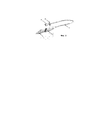
[00018] На Фиг. 3 показан общий вид назального аспиратора, согласно одному из вариантов реализации предлагаемой полезной модели. [00018] In FIG. 3 shows a General view of the nasal aspirator, according to one embodiment of the proposed utility model.
ОСУЩЕСТВЛЕНИЕ ПОЛЕЗНОЙ МОДЕЛИIMPLEMENTATION OF A USEFUL MODEL
[00019] Согласно одному из предпочтительных вариантов реализации настоящей полезной модели, аспиратор содержит разъемный корпус (1), содержащий разъёмно соединённые проксимальную часть (4) и дистальную часть (5) (Фиг. 1). Проксимальная часть (4) аспиратора разделена перегородкой (9) на первую часть (3) и вторую часть (2). При использовании аспиратор предпочтительно располагать таким образом, что первая часть (3) находится над второй частью (2). На Фиг. 1 аспиратор показан в собранном виде, при этом отверстие (5) для принятия вычищаемого содержимого находится во второй части (2), а отверстие (8) для присоединения к источнику отрицательного давления посредством внутреннего канала (7) сообщается с первой частью (3). Когда аспиратор собран и проксимальная часть (4) соединена с дистальной частью (6), канал (7) входит в первую часть (3) проксимальной части с заведением его конца за край перегородки (9), при этом между первой частью (3) и второй частью (2) обеспечен воздухообмен. Следует отметить, что более глубокое введение канала (7) во вторую часть (2) позволяет обеспечить дополнительную надежность предотвращения попадания вычищаемого содержимого в область отверстия (8) для присоединения к источнику отрицательного давления. [00019] According to one of the preferred embodiments of the present utility model, the aspirator comprises a detachable body (1) comprising detachably connected proximal part (4) and a distal part (5) (Fig. 1). The proximal part (4) of the aspirator is divided by a septum (9) into the first part (3) and the second part (2). In use, the aspirator is preferably positioned so that the first part (3) is located above the second part (2). In FIG. 1, the aspirator is shown assembled, with the hole (5) for receiving the scrubbed contents being in the second part (2), and the hole (8) for connecting to the negative pressure source through the internal channel (7) communicates with the first part (3). When the aspirator is assembled and the proximal part (4) is connected to the distal part (6), the channel (7) enters the first part (3) of the proximal part with the end of it past the edge of the septum (9), while between the first part (3) and the second part (2) provides air exchange. It should be noted that a deeper introduction of the channel (7) into the second part (2) allows for additional reliability to prevent the scrubbed contents from entering the region of the hole (8) for connection to a negative pressure source.
[00020] На Фиг. 1 также стрелками показаны направления воздушного потока (пунктиром) и потока вычищаемого содержимого (непрерывной линией). Видно, что под действием отрицательного давления, создаваемого в корпусе после подключения к отверстию (8) источника отрицательного давления, поток воздуха проходит от отверстия (5) для принятия вычищаемого содержимого во вторую камеру (2), а затем через пространство, образованное между внутренней поверхностью первой части (3) проксимальной части (4) и стенками канала (7), в первую камеру (3). После этого у потока воздуха имеется единственный путь дальнейшего распространения – через канал (7), являющийся продолжением отверстия (8) для присоединения к источнику отрицательного давления. При этом вычищаемое содержимое под действием создаваемого в корпусе аспиратора отрицательного давления вынуждено входить в отверстие (5) для принятия вычищаемого содержимого и попадает во вторую часть (2) проксимальной части (4). При этом попаданию вычищаемого содержимого в область окончания канала (7), являющегося продолжением отверстия (8) для присоединения к источнику отрицательного давления, возникает несколько препятствий, обусловленных как естественными условиями (силой тяжести и адгезией вязкого вычищаемого содержимого к внутренней поверхности корпуса (1)), так и предусмотренными для этого конструктивными особенностями: поступающее во вторую камеру (2) содержимое отделено от окончания канала (7) не только перегородкой (9), но и стенками канала (7), являющегося продолжение отверстия (8) для присоединения к источнику отрицательного давления. [00020] FIG. 1, arrows also indicate the directions of the air flow (dotted line) and the flow of the contents being scrubbed (continuous line). It is seen that under the influence of negative pressure created in the housing after connecting a negative pressure source to the hole (8), the air flow passes from the hole (5) to receive the contents to be cleaned into the second chamber (2), and then through the space formed between the inner surface the first part (3) of the proximal part (4) and the walls of the channel (7), into the first chamber (3). After that, the air flow has the only way for further propagation - through the channel (7), which is a continuation of the hole (8) for connection to a negative pressure source. In this case, the scrubbed contents under the action of negative pressure created in the aspirator body is forced to enter the hole (5) for receiving the scrubbed contents and enters the second part (2) of the proximal part (4). In this case, getting the scrubbed contents into the region of the end of the channel (7), which is a continuation of the hole (8) for connecting to the source of negative pressure, causes several obstacles caused by both natural conditions (gravity and adhesion of viscous scrubbed contents to the inner surface of the housing (1)) and design features provided for this: the contents entering the second chamber (2) are separated from the end of the channel (7) not only by a partition (9), but also by the walls of the channel (7), which rodolzhenie holes (8) for connection to a negative pressure source.
[00021] В представленном на фигурах варианте реализации полезной модели разделительная перегородка (9) выполнена в проксимальной части (4) корпуса, так что при соединении проксимальной и дистальной частей корпуса окончание внутреннего канала (7) заходит в первую часть (3) и находится на некотором отдалении от края разделительной перегородки (9). [00021] In the embodiment of the utility model shown in the figures, the dividing wall (9) is made in the proximal part (4) of the body, so that when connecting the proximal and distal parts of the body, the end of the internal channel (7) enters the first part (3) and is located on some distance from the edge of the partition wall (9).
[00022] На Фиг. 2А-2В показан вид в разрезе по линии А-А проксимальной части (4), дистальной части (6) и корпуса (1) в сборе, согласно одному из вариантов реализации предлагаемой полезной модели. Согласно показанному варианту реализации, между проксимальной и дистальной частями (4, 6) корпуса (1) реализовано телескопическое соединение. Для этого дистальный конец проксимальной части (4) имеет диаметр, обеспечивающий его вставку в ответную часть дистальной части (6) с её плотной посадкой на проксимальную часть (4). Как видно на Фиг. 2А, перегородка (9) выполнена в проксимальной части (4). На Фиг. 2Б показан вид в разрезе дистальной части, которая содержит канал (7), являющийся продолжением отверстия (8) для присоединения к источнику отрицательного давления. Согласно показанному варианту реализации полезной модели, канал (7) выполнен с технологическим элементом (11) жесткости, обеспечивающим жесткость конструкции и упрощающим производство изделия. При соединении проксимальной части (4) и дистальной части (6) канал (7) входит в первую часть (3) проксимальной части (4) корпуса. При этом между стенками канала (7) и внутренней поверхностью верхней части (3), находящейся в проксимальной части (4) корпуса, образуется пространство для воздухообмена между частями (2 и 3). Таким образом, предотвращено попадание вычищаемого содержимого из второй части (2) в первую часть (3) и во внутренний канал (7), что в свою очередь предотвращает попадание вычищаемого содержимого в область отверстия (8) для присоединения к источнику отрицательного давления, благодаря тому, что принимающая вычищаемое содержимое вторая часть (3) проксимальной части (4) корпуса отделена от отверстия (8) для присоединения к источнику отрицательного давления перегородкой (9), а также стенками канала (7). [00022] FIG. 2A-2B show a sectional view along line AA of the proximal part (4), the distal part (6) and the body (1) assembly, according to one embodiment of the proposed utility model. According to the shown embodiment, between the proximal and distal parts (4, 6) of the body (1), a telescopic connection is realized. For this, the distal end of the proximal part (4) has a diameter that ensures its insertion into the mating part of the distal part (6) with its tight fit on the proximal part (4). As seen in FIG. 2A, the septum (9) is made in the proximal part (4). In FIG. 2B shows a cross-sectional view of a distal part that contains a channel (7), which is a continuation of the hole (8) for connection to a negative pressure source. According to the shown embodiment of the utility model, the channel (7) is made with a technological stiffness element (11), which provides structural rigidity and simplifies the production of the product. When connecting the proximal part (4) and the distal part (6), the channel (7) is included in the first part (3) of the proximal part (4) of the body. In this case, between the walls of the channel (7) and the inner surface of the upper part (3) located in the proximal part (4) of the body, a space is formed for air exchange between parts (2 and 3). Thus, the scrubbed contents from the second part (2) are prevented from entering the first part (3) and into the inner channel (7), which in turn prevents the scrubbed contents from entering the region of the hole (8) for attaching to the negative pressure source, thereby that the receiving scrubbed contents of the second part (3) of the proximal part (4) of the body is separated from the hole (8) for connection to the negative pressure source by a partition (9), as well as the walls of the channel (7).
[00023] Для удобства применения предлагаемого аспиратора, согласно некоторым вариантам реализации полезной модели, область проксимальной части, в которой находится отверстие (5) для принятия вычищаемого содержимого, выполнена конусоподобной формы, формы выпуклого тела вращения и/или округлой вытянутой формы, обеспечивающей возможность вставлять указанную область в носовой проход. Такое выполнение проксимальной части (4) корпуса (1) обеспечивает более надежный обмен текучей средой между аспиратором и верхними дыхательными путями. [00023] For the convenience of using the proposed aspirator, according to some embodiments of the utility model, the region of the proximal part in which the hole (5) for receiving the scrubbed contents is located is made conical in shape, in shape of a convex body of revolution and / or in a round elongated shape, which makes it possible to insert specified area in the nasal passage. This embodiment of the proximal part (4) of the housing (1) provides a more reliable fluid exchange between the aspirator and the upper respiratory tract.
[00024] Для повышения атравматичности аспиратора по меньшей мере область проксимальной части, в которой находится отверстие (5) для принятия вычищаемого содержимого, выполнена из эластичного материала. Для обеспечения более герметичного соединения проксимальной части (4) и дистальной части (6) предпочтительно вся проксимальная часть (4) корпуса (1) аспиратора выполнена из эластичного материала (например, силикона и т.п.). [00024] To increase the atraumaticity of the aspirator, at least the region of the proximal portion in which the opening (5) for receiving the scrubbed contents is made of elastic material. In order to provide a more tight connection between the proximal part (4) and the distal part (6), preferably the entire proximal part (4) of the aspirator body (1) is made of an elastic material (for example, silicone and the like).
[00025] Использование предлагаемого аспиратора по назначению возможно как совместно со специальными устройствами, создающими отрицательное давление (например, компрессорами, микрокомпреccорами), так и без специальных устройств, в качестве упрощенного домашнего средства очищения верхних дыхательных путей путём создания давления вдохом со стороны отверстия для присоединения к источнику отрицательного давления. Для удобства расположения аспиратора при его использовании, согласно некоторым вариантам реализации, предусмотрено также наличие у него эластичной трубки (10), выполненной с возможностью присоединения одним из концов к отверстию (8) для присоединения к источнику отрицательного давления. Другим концом эластичную трубку (10) присоединяют к источнику отрицательного давления. Кроме того, для домашнего применения, согласно некоторым вариантам реализации предлагаемой полезной модели, предусмотрено наличие мундштука (11), выполненного с возможностью присоединения к указанной трубке (10), а при необходимости также ограничителя (12), выполненного с возможностью присоединения к эластичной трубке (10) между нею и мундштуком (11). Ограничитель (12) может быть выполнен в виде трубчатой части, содержащей конусовидное утолщение, препятствующее чрезмерной вставки мундштука (11) в эластичную трубку (10). На показанном на Фиг. 3 варианте реализации ограничитель (12) для удобства также содержит широкую закраину, которая, согласно показанному варианту реализации, выполнена в виде лепестков. В некоторых других вариантах реализации, предполагающих использование аспиратора для очищения верхних дыхательных путей детей, ограничитель (12) может быть выполнен в виде любого другого отвлекающего внимание ребенка элемента. В других вариантах реализации эластичную трубку присоединяют к компрессору или микрокомпрессору, например через штуцер.[00025] The intended use of the proposed aspirator is possible both in conjunction with special devices that create negative pressure (for example, compressors, microcompressors), and without special devices, as a simplified home remedy for cleaning the upper respiratory tract by creating inspiratory pressure from the side of the access hole to a source of negative pressure. For the convenience of the location of the aspirator when using it, according to some implementation options, it is also provided that it has an elastic tube (10) made with the possibility of attaching one of the ends to the hole (8) for connection to a negative pressure source. At the other end, an elastic tube (10) is connected to a negative pressure source. In addition, for home use, according to some embodiments of the proposed utility model, a mouthpiece (11) is provided that is configured to attach to said tube (10), and if necessary also a limiter (12) configured to attach to an elastic tube ( 10) between her and the mouthpiece (11). The limiter (12) can be made in the form of a tubular part containing a cone-shaped thickening that prevents excessive insertion of the mouthpiece (11) into the elastic tube (10). As shown in FIG. 3 embodiment, the limiter (12) for convenience also contains a wide flange, which, according to the shown embodiment, is made in the form of petals. In some other embodiments involving the use of an aspirator to clean the upper respiratory tract of children, the limiter (12) can be made in the form of any other element that distracts the attention of the child. In other embodiments, an elastic tube is attached to a compressor or microcompressor, for example via a fitting.
[00026] Использование предлагаемого аспиратора интуитивно понятно и легко осуществимо в домашних условиях. Для очищения верхних дыхательных путей область проксимальной части (4) корпуса (1) аспиратора, в которой находится отверстие (5) для принятия вычищаемого содержимого, располагают с обеспечением обмена текучей средой с носовым проходом пациента, а затем обеспечивают отрицательное давление внутри корпуса (1) аспиратора, которое вынуждает имеющиеся в верхних дыхательных путях скопления слизи и/или других субстанций перемещаться через отверстие (5) для принятия вычищаемого содержимого во вторую часть (2) проксимальной части (4) корпуса. При применении предлагаемого устройства без специальных устройств к отверстию (8) присоединяют эластичную трубку (10) и к ней присоединяют мундштук (11). Область проксимальной части (4) корпуса (1) аспиратора, в которой находится отверстие (5) для принятия вычищаемого содержимого, располагают с обеспечением обмена текучей средой с носовым проходом пациента, мундштук (11) плотно обхватывают губами, а затем совершают вдох, который и приводит к возникновению отрицательного давления внутри корпуса (1) аспиратора. [00026] Using the proposed aspirator is intuitive and easy to do at home. To clean the upper respiratory tract, the area of the proximal part (4) of the aspirator body (1) in which the hole (5) for receiving the scrubbed contents is located is arranged to exchange fluid with the patient’s nasal passage and then provide negative pressure inside the case (1) an aspirator, which forces the accumulations of mucus and / or other substances present in the upper respiratory tract to move through the opening (5) to accept the scrubbed contents into the second part (2) of the proximal part (4) of the body. When using the proposed device without special devices, an elastic tube (10) is attached to the hole (8) and a mouthpiece (11) is attached to it. The area of the proximal part (4) of the aspirator body (1), in which the hole (5) for receiving the scrubbed contents is located, is arranged to exchange fluid with the patient’s nasal passage, the mouthpiece (11) is tightly wrapped around the lips, and then a breath is taken which leads to the occurrence of negative pressure inside the housing (1) of the aspirator.
[00027] Для проведения санитарно-гигиенической обработки предлагаемого аспиратора все его составные части разъединяют и промывают в воде, мыльном растворе, стерилизующем растворе и/или стерилизуют путем термической обработки в случае, если таковая возможна в отношении использованных при изготовлении материалов. Важным преимуществом при этом является то, что конструкция корпуса предлагаемого аспиратора обеспечивает легкодоступность его внутренней поверхности для различных очищающих агентов. Кроме того, так как предлагаемая конструкция надежно предохраняет верхнюю камеру (3), канал (7) и тем более соединенное с ним отверстие (8) для присоединения к источнику отрицательного давления от попадания в них вычищаемого содержимого, санитарно-гигиеническая обработка аспиратора также упрощается. [00027] To carry out the sanitary-hygienic treatment of the proposed aspirator, all its components are separated and washed in water, a soap solution, a sterilizing solution and / or sterilized by heat treatment if this is possible with respect to the materials used in the manufacture. An important advantage in this case is that the housing design of the proposed aspirator provides easy access to its inner surface for various cleaning agents. In addition, since the proposed design reliably protects the upper chamber (3), the channel (7), and even more the hole (8) connected to it for attaching to the source of negative pressure from ingress of scrubbed contents, the sanitary-hygienic treatment of the aspirator is also simplified.
[00028] Следует понимать, что описанные здесь варианты реализации предложенного технического решения приведены только в качестве примера и не ограничивают сущность настоящего изобретения, которая задана исключительно прилагаемой формулой полезной модели. Все описанные здесь варианты реализации могут быть полностью или частично скомбинированы без отступления от сущности настоящей полезной модели и без потери преимуществ, обеспечиваемых предложенной полезной моделью. Специалисту в области техники понятно, что материалы, типы соединений, форма внутренних полостей, а также другие особенности аспиратора могут быть различными без отступления от сущности полезной модели и не умаляя при этом обеспечиваемых ею преимуществ. [00028] It should be understood that the embodiments of the proposed technical solution described here are given only as an example and do not limit the essence of the present invention, which is defined solely by the attached utility model formula. All of the implementation options described here can be fully or partially combined without departing from the essence of the present utility model and without losing the benefits provided by the proposed utility model. One skilled in the art will understand that materials, types of joints, the shape of internal cavities, and other features of an aspirator can be different without departing from the essence of the utility model and without detracting from the benefits it provides.
Claims (10)
Priority Applications (1)
| Application Number | Priority Date | Filing Date | Title |
|---|---|---|---|
| RU2017128547U RU178012U1 (en) | 2017-08-10 | 2017-08-10 | Nasal Aspirator |
Applications Claiming Priority (1)
| Application Number | Priority Date | Filing Date | Title |
|---|---|---|---|
| RU2017128547U RU178012U1 (en) | 2017-08-10 | 2017-08-10 | Nasal Aspirator |
Publications (1)
| Publication Number | Publication Date |
|---|---|
| RU178012U1 true RU178012U1 (en) | 2018-03-19 |
Family
ID=61627517
Family Applications (1)
| Application Number | Title | Priority Date | Filing Date |
|---|---|---|---|
| RU2017128547U RU178012U1 (en) | 2017-08-10 | 2017-08-10 | Nasal Aspirator |
Country Status (1)
| Country | Link |
|---|---|
| RU (1) | RU178012U1 (en) |
Citations (4)
| Publication number | Priority date | Publication date | Assignee | Title |
|---|---|---|---|---|
| US6517511B2 (en) * | 2001-06-22 | 2003-02-11 | Tzu-Chiang Yao | Cleansable multi-purpose nasal discharge aspirator |
| RU87082U1 (en) * | 2007-12-19 | 2009-09-27 | Иллеш Чок Эш Тарша Ккт. | NOSE ASpirator ATTACHED TO A VACUUM ACCESS CLEANER |
| US7862536B2 (en) * | 2007-06-15 | 2011-01-04 | Avita Corporation | Combined nasal spray and aspirator device |
| RU2471472C2 (en) * | 2007-03-06 | 2013-01-10 | РиноСистемс Инк. | Nasal rinsing systems and methods |
-
2017
- 2017-08-10 RU RU2017128547U patent/RU178012U1/en active
Patent Citations (4)
| Publication number | Priority date | Publication date | Assignee | Title |
|---|---|---|---|---|
| US6517511B2 (en) * | 2001-06-22 | 2003-02-11 | Tzu-Chiang Yao | Cleansable multi-purpose nasal discharge aspirator |
| RU2471472C2 (en) * | 2007-03-06 | 2013-01-10 | РиноСистемс Инк. | Nasal rinsing systems and methods |
| US7862536B2 (en) * | 2007-06-15 | 2011-01-04 | Avita Corporation | Combined nasal spray and aspirator device |
| RU87082U1 (en) * | 2007-12-19 | 2009-09-27 | Иллеш Чок Эш Тарша Ккт. | NOSE ASpirator ATTACHED TO A VACUUM ACCESS CLEANER |
Similar Documents
| Publication | Publication Date | Title |
|---|---|---|
| JP6729707B2 (en) | Nasal Mucus Aspirator Accessories, Nasal Mucus Aspirator, Kit | |
| BR0209268B1 (en) | APPLIANCE TO DISTRIBUTE LIQUID WITHIN A HUMAN NARINA | |
| US20100331777A1 (en) | Nose device | |
| US20060229567A1 (en) | Suction tip holster insert | |
| RU178012U1 (en) | Nasal Aspirator | |
| KR200454366Y1 (en) | A medical suction machine | |
| EP1474186B1 (en) | Infant nasal aspirator | |
| CN214345470U (en) | Department of anesthesia uses respiratory filter | |
| KR101088301B1 (en) | Assistant apparatus for oral treatment | |
| CN211986447U (en) | Sputum suction nursing device for department of pediatrics | |
| CN208710128U (en) | A kind of dental three ways syringe jet stem with filtering function | |
| CN214049931U (en) | Sputum collection device | |
| CN109939326B (en) | Olfactory training device based on expiratory pressure | |
| RU2349298C2 (en) | Device for infant feeding by expressed milk or milk formula | |
| KR200234171Y1 (en) | Runny nose | |
| CN216021270U (en) | Pediatric neonate nostril cleaning device | |
| CN218010348U (en) | Nasal cleaner | |
| CN210250130U (en) | Degassing unit for department of stomatology | |
| CN213788932U (en) | Spittoon collecting device | |
| CN210644700U (en) | Novel sputum excretion device for pediatric patient nursing | |
| CN210170632U (en) | Olfactory sensation training device and system based on expiratory pressure | |
| WO2005118021A1 (en) | Electric nasal passage cleaning apparatus | |
| CN213347335U (en) | Novel infection prevention device for patient in department of respiration | |
| CN213994510U (en) | Air filtering and sputum splashing prevention device | |
| KR101088300B1 (en) | Breathing filter and assistant apparatus for oral treatment having the same |