RU1706339C - Valve for chemical current source - Google Patents
Valve for chemical current source Download PDFInfo
- Publication number
- RU1706339C RU1706339C SU904822177A SU4822177A RU1706339C RU 1706339 C RU1706339 C RU 1706339C SU 904822177 A SU904822177 A SU 904822177A SU 4822177 A SU4822177 A SU 4822177A RU 1706339 C RU1706339 C RU 1706339C
- Authority
- RU
- Russia
- Prior art keywords
- valve
- lid
- current source
- gas
- ring
- Prior art date
Links
- 239000000126 substance Substances 0.000 title claims abstract description 8
- 238000004870 electrical engineering Methods 0.000 abstract 1
- 238000005452 bending Methods 0.000 description 3
- 239000000463 material Substances 0.000 description 3
- 238000004519 manufacturing process Methods 0.000 description 2
- 238000003466 welding Methods 0.000 description 2
- 238000004026 adhesive bonding Methods 0.000 description 1
- OJIJEKBXJYRIBZ-UHFFFAOYSA-N cadmium nickel Chemical compound [Ni].[Cd] OJIJEKBXJYRIBZ-UHFFFAOYSA-N 0.000 description 1
- 239000003792 electrolyte Substances 0.000 description 1
- 238000000034 method Methods 0.000 description 1
- 230000001105 regulatory effect Effects 0.000 description 1
Images
Classifications
-
- Y—GENERAL TAGGING OF NEW TECHNOLOGICAL DEVELOPMENTS; GENERAL TAGGING OF CROSS-SECTIONAL TECHNOLOGIES SPANNING OVER SEVERAL SECTIONS OF THE IPC; TECHNICAL SUBJECTS COVERED BY FORMER USPC CROSS-REFERENCE ART COLLECTIONS [XRACs] AND DIGESTS
- Y02—TECHNOLOGIES OR APPLICATIONS FOR MITIGATION OR ADAPTATION AGAINST CLIMATE CHANGE
- Y02E—REDUCTION OF GREENHOUSE GAS [GHG] EMISSIONS, RELATED TO ENERGY GENERATION, TRANSMISSION OR DISTRIBUTION
- Y02E60/00—Enabling technologies; Technologies with a potential or indirect contribution to GHG emissions mitigation
- Y02E60/10—Energy storage using batteries
Landscapes
- Gas Exhaust Devices For Batteries (AREA)
Abstract
Description
Изобретение относится к электротехнической промышленности и может быть использовано в химических источниках тока (ХИТ), в частности в никель-кадмиевых аккумуляторах. The invention relates to the electrical industry and can be used in chemical current sources (HIT), in particular in nickel-cadmium batteries.
Известен клапан для герметизированной батареи, содержащий корпус, закрепленный в гнезде крышки с помощью сваривания или склеивания. На корпусе имеется заправочная трубка, конец которой заглушен эластичным резиновым элементом, срабатывающим от действующего на него внутреннего избыточного давления и стравливающим газ. Known valve for a sealed battery containing a housing fixed in the socket of the cover by welding or gluing. On the body there is a filling tube, the end of which is plugged with an elastic rubber element, which is activated by the internal overpressure acting on it and bleeds the gas.
Недостатком такого клапана является невозможность регулирования давления его срабатывания, а также сложность конструкции. The disadvantage of this valve is the inability to control the pressure of its operation, as well as the complexity of the design.
Наиболее близким к изобретению является герметичный аккумулятор с клапаном, содержащий корпус, крышку с отверстием, стержень со шляпкой, помещенный в отверстие, эластичное кольцо, надетое на стержень, и каналы для свободного выхода газа, причем на шляпку стержня, снабженную резьбой, навинчен кольцевой упорный регулятор, упирающийся в поверхность крышки. Одним из вариантов этого технического решения является то, что стержень со шляпкой имеет в нижней части резьбу, на которой навинчена гайка, упирающаяся во внутреннюю поверхность крышки. Closest to the invention is a sealed battery with a valve, comprising a housing, a cover with a hole, a rod with a cap placed in the hole, an elastic ring worn on the rod, and channels for the free exit of gas, moreover, a thrust ring is screwed onto the rod cap equipped with a thread. regulator abutting against the surface of the lid. One of the options for this technical solution is that the rod with the cap has a thread in the lower part, on which a nut is screwed, abutting against the inner surface of the cap.
Недостатком этого герметичного аккумулятора с клапаном является сложность конструкции, обусловленная большим количеством деталей. The disadvantage of this sealed battery with a valve is the design complexity due to the large number of parts.
Целью изобретения является упрощение конструкции клапана для химических источников тока. The aim of the invention is to simplify the design of the valve for chemical power sources.
Эта цель достигается тем, что клапан для химических источников тока выполнен в виде корпуса, крышки, между которыми установлено эластичное кольцо. This goal is achieved by the fact that the valve for chemical current sources is made in the form of a housing, a cover, between which an elastic ring is installed.
В крышке выполнены просечные отгибаемые лепестки, с помощью которых производится пережатие участков эластичного кольца (деформирование). При этом перераспределяется часть материала кольца, что приводит к изменению его упругости в пережатых участках, по которым стравливается избыточное давление газа, а тем самым изменяется давление срабатывания клапана. Perforated bending petals are made in the lid, with the help of which the sections of the elastic ring are clamped (deformation). At the same time, part of the ring material is redistributed, which leads to a change in its elasticity in the pinched areas along which the excess gas pressure is vented, and thereby the valve operating pressure changes.
Упрощение конструкции за счет сокращения числа деталей клапана приводит к уменьшению затрат на его изготовление. Simplification of the design by reducing the number of valve parts reduces the cost of its manufacture.
Путем местного частичного пережима (деформации) эластичного кольца лепестками крышки происходит изменение геометрических размеров и перераспределение материала кольца, а следовательно, и его упругих свойств. В свою очередь, это приводит к изменению давления срабатывания клапана, соответствующего определенной степени заряженности аккумулятора. By local partial pinching (deformation) of the elastic ring by the cover petals, the geometric dimensions are changed and the material of the ring is redistributed, and hence its elastic properties. In turn, this leads to a change in the response pressure of the valve, corresponding to a certain degree of charge of the battery.
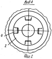
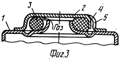
На фиг. 1 изображен продольный разрез клапана; на фиг. 2 - вид А на фиг. 1; на фиг. 3 - продольный разрез клапана с крышкой расположенной с наружной стороны корпуса. In FIG. 1 shows a longitudinal section through a valve; in FIG. 2 is a view A in FIG. 1; in FIG. 3 is a longitudinal section through a valve with a cover located on the outside of the housing.
Клапан содержит корпус 1, являющийся частью корпуса аккумулятора, и приваренную к нему точечной сваркой крышку 2. Между корпусом 1 и крышкой 2 помещено эластичное кольцо 3. В крышке 2 выполнены просечки в виде лепестков 4. Для прохода газа служат отверстия 5. The valve comprises a housing 1, which is part of the battery housing, and a
В процессе заряда аккумулятора из электролита начинает выделяться газ, в связи с чем давление внутри корпуса 1 повышается. Под действием этого давления кольцо 3 отжимается от посадочных мест крышки 2 и корпуса 1, открывая тем самым выход газу. Регулирование давления срабатывания клапана осуществляется следующим образом. In the process of charging the battery from the electrolyte gas begins to be released, and therefore the pressure inside the housing 1 rises. Under the influence of this pressure, the
Подгибая лепестки 4 (часть или все) в сторону кольца или от него, обеспечивают перераспределение материала кольца (деформирование), а тем самым усилия поджатия его к крышке 2 и корпусу 1 и, соответственно, изменяется давление, при котором стравливается газ. Bending the petals 4 (part or all) to the side of the ring or away from it, redistributes the material of the ring (deformation), and thereby forces it to be pressed against the
В связи с тем, что отгибание лепестков 4 производится плавным изменением, то точность срабатывания может быть осуществлена как перед установкой его в аккумулятор, так и после установки в аккумулятор. Due to the fact that the bending of the
Технико-экономическое преимущество устройства заключается в том, что при простой конструкции клапана достигается регулирование давления внутри аккумулятора, а тем самым степени его заряда или емкости, что, в свою очередь, позволяет обеспечить во всей изготовляемой партии аккумуляторов одинаковые энергетические характеристики (метрологическое обеспечение). The technical and economic advantage of the device lies in the fact that with a simple valve design, pressure inside the accumulator is regulated, and thereby the degree of its charge or capacity, which, in turn, makes it possible to ensure the same energy characteristics in the entire production batch of batteries (metrological support).
Кроме этого, упрощение конструкции клапана, за счет снижения количества входящих в него деталей, уменьшает его себестоимость. In addition, simplifying the design of the valve, by reducing the number of parts included in it, reduces its cost.
Claims (1)
Priority Applications (1)
| Application Number | Priority Date | Filing Date | Title |
|---|---|---|---|
| SU904822177A RU1706339C (en) | 1990-05-07 | 1990-05-07 | Valve for chemical current source |
Applications Claiming Priority (1)
| Application Number | Priority Date | Filing Date | Title |
|---|---|---|---|
| SU904822177A RU1706339C (en) | 1990-05-07 | 1990-05-07 | Valve for chemical current source |
Publications (1)
| Publication Number | Publication Date |
|---|---|
| RU1706339C true RU1706339C (en) | 1994-11-30 |
Family
ID=30441783
Family Applications (1)
| Application Number | Title | Priority Date | Filing Date |
|---|---|---|---|
| SU904822177A RU1706339C (en) | 1990-05-07 | 1990-05-07 | Valve for chemical current source |
Country Status (1)
| Country | Link |
|---|---|
| RU (1) | RU1706339C (en) |
-
1990
- 1990-05-07 RU SU904822177A patent/RU1706339C/en active
Non-Patent Citations (2)
| Title |
|---|
| Авторское свидетельство СССР N 864388, кл. H 01M 10/34, 1977. * |
| Заявка Франции N 2576149, кл. H 01M 2/12, 1986. * |
Similar Documents
| Publication | Publication Date | Title |
|---|---|---|
| EP4350864A3 (en) | Battery pack, vehicle, and energy storage device | |
| GB1511766A (en) | Electrochemical cells | |
| JPH0511385B2 (en) | ||
| SE7409895L (en) | ||
| US4077100A (en) | Method of forming pressure accumulator | |
| KR970705192A (en) | ELECTRIC VEHICLE CELL | |
| KR102217448B1 (en) | The Secondary Battery And The Method For Manufacturing Therefore | |
| US6080506A (en) | Pressure activated current interrupter for electrochemical cells | |
| EP1311019A3 (en) | Lithium secondary battery | |
| RU1706339C (en) | Valve for chemical current source | |
| US4189528A (en) | Power module assembly | |
| JPS6260793B2 (en) | ||
| KR20210054703A (en) | Gas analysis apparatus for cylindrical battery cells and gas analysis methods | |
| US7807282B2 (en) | Nickel-metal hydride storage battery | |
| TW341734B (en) | Charger for wireless microphone | |
| JPS5725679A (en) | Sealed storage battery | |
| US3736188A (en) | Battery of reserve cells | |
| SU597354A3 (en) | Vehicle lead accumulator | |
| US4642599A (en) | Control device | |
| PL90561B1 (en) | ||
| GB1359004A (en) | Gas-tight galvanic cell | |
| US2803494A (en) | Thermo-actuator | |
| CN2209381Y (en) | Compression spring energy storage mechanism of vacuum circuit breaker | |
| GB2058456A (en) | Monitoring gas pressure during charging of electric storage batteries | |
| JPH0574433A (en) | Enclosed lead-acid storage battery |