RU167883U1 - A device for preparing and supplying air to an internal combustion engine. - Google Patents
A device for preparing and supplying air to an internal combustion engine. Download PDFInfo
- Publication number
- RU167883U1 RU167883U1 RU2015130283U RU2015130283U RU167883U1 RU 167883 U1 RU167883 U1 RU 167883U1 RU 2015130283 U RU2015130283 U RU 2015130283U RU 2015130283 U RU2015130283 U RU 2015130283U RU 167883 U1 RU167883 U1 RU 167883U1
- Authority
- RU
- Russia
- Prior art keywords
- air
- internal combustion
- combustion engine
- compressor
- cylinder
- Prior art date
Links
- 238000002485 combustion reaction Methods 0.000 title claims abstract description 55
- 238000003860 storage Methods 0.000 claims abstract description 12
- 238000004887 air purification Methods 0.000 claims abstract description 7
- 238000001816 cooling Methods 0.000 claims abstract description 7
- 238000007599 discharging Methods 0.000 claims abstract description 4
- 238000002360 preparation method Methods 0.000 abstract description 5
- 239000007789 gas Substances 0.000 description 10
- 230000006835 compression Effects 0.000 description 9
- 238000007906 compression Methods 0.000 description 9
- 238000007664 blowing Methods 0.000 description 7
- 239000000446 fuel Substances 0.000 description 7
- 238000002347 injection Methods 0.000 description 5
- 239000007924 injection Substances 0.000 description 5
- 239000000243 solution Substances 0.000 description 5
- 239000000203 mixture Substances 0.000 description 4
- 238000003825 pressing Methods 0.000 description 4
- 230000009467 reduction Effects 0.000 description 3
- 230000001133 acceleration Effects 0.000 description 2
- 239000002826 coolant Substances 0.000 description 2
- 238000009826 distribution Methods 0.000 description 2
- 239000012535 impurity Substances 0.000 description 2
- 239000002245 particle Substances 0.000 description 2
- 229920000049 Carbon (fiber) Polymers 0.000 description 1
- VYPSYNLAJGMNEJ-UHFFFAOYSA-N Silicium dioxide Chemical class O=[Si]=O VYPSYNLAJGMNEJ-UHFFFAOYSA-N 0.000 description 1
- XAGFODPZIPBFFR-UHFFFAOYSA-N aluminium Chemical compound [Al] XAGFODPZIPBFFR-UHFFFAOYSA-N 0.000 description 1
- 229910052782 aluminium Inorganic materials 0.000 description 1
- 230000008901 benefit Effects 0.000 description 1
- 230000015572 biosynthetic process Effects 0.000 description 1
- 238000004364 calculation method Methods 0.000 description 1
- 239000004917 carbon fiber Substances 0.000 description 1
- 238000006243 chemical reaction Methods 0.000 description 1
- 239000003638 chemical reducing agent Substances 0.000 description 1
- 238000004140 cleaning Methods 0.000 description 1
- 238000005056 compaction Methods 0.000 description 1
- 230000006378 damage Effects 0.000 description 1
- 230000000694 effects Effects 0.000 description 1
- 239000012530 fluid Substances 0.000 description 1
- 230000007246 mechanism Effects 0.000 description 1
- VNWKTOKETHGBQD-UHFFFAOYSA-N methane Chemical compound C VNWKTOKETHGBQD-UHFFFAOYSA-N 0.000 description 1
- 238000000034 method Methods 0.000 description 1
- 230000002028 premature Effects 0.000 description 1
- 230000008569 process Effects 0.000 description 1
- 238000000926 separation method Methods 0.000 description 1
- 239000000741 silica gel Substances 0.000 description 1
- 229910002027 silica gel Inorganic materials 0.000 description 1
- 230000001360 synchronised effect Effects 0.000 description 1
Images
Classifications
-
- F—MECHANICAL ENGINEERING; LIGHTING; HEATING; WEAPONS; BLASTING
- F02—COMBUSTION ENGINES; HOT-GAS OR COMBUSTION-PRODUCT ENGINE PLANTS
- F02B—INTERNAL-COMBUSTION PISTON ENGINES; COMBUSTION ENGINES IN GENERAL
- F02B29/00—Engines characterised by provision for charging or scavenging not provided for in groups F02B25/00, F02B27/00 or F02B33/00 - F02B39/00; Details thereof
- F02B29/06—After-charging, i.e. supplementary charging after scavenging
-
- F—MECHANICAL ENGINEERING; LIGHTING; HEATING; WEAPONS; BLASTING
- F02—COMBUSTION ENGINES; HOT-GAS OR COMBUSTION-PRODUCT ENGINE PLANTS
- F02M—SUPPLYING COMBUSTION ENGINES IN GENERAL WITH COMBUSTIBLE MIXTURES OR CONSTITUENTS THEREOF
- F02M23/00—Apparatus for adding secondary air to fuel-air mixture
- F02M2023/008—Apparatus for adding secondary air to fuel-air mixture by injecting compressed air directly into the combustion chamber
-
- Y—GENERAL TAGGING OF NEW TECHNOLOGICAL DEVELOPMENTS; GENERAL TAGGING OF CROSS-SECTIONAL TECHNOLOGIES SPANNING OVER SEVERAL SECTIONS OF THE IPC; TECHNICAL SUBJECTS COVERED BY FORMER USPC CROSS-REFERENCE ART COLLECTIONS [XRACs] AND DIGESTS
- Y02—TECHNOLOGIES OR APPLICATIONS FOR MITIGATION OR ADAPTATION AGAINST CLIMATE CHANGE
- Y02T—CLIMATE CHANGE MITIGATION TECHNOLOGIES RELATED TO TRANSPORTATION
- Y02T10/00—Road transport of goods or passengers
- Y02T10/10—Internal combustion engine [ICE] based vehicles
- Y02T10/12—Improving ICE efficiencies
Landscapes
- Compressors, Vaccum Pumps And Other Relevant Systems (AREA)
Abstract
Полезная модель относится к двигателям внутреннего сгорания. Техническим результатом является повышение качества подготовки и подачи воздуха в цилиндр двигателя внутреннего сгорания. Сущность полезной модели заключается в том, что устройство подготовки и подачи воздуха в двигатель внутреннего сгорания, содержащем компрессор для сжатия воздуха, накопитель сжатого воздуха, как минимум один инжектор для вдувания воздуха в цилиндр двигателя внутреннего сгорания, содержит фильтр очистки воздуха, расположенный на входе в компрессор, устройство для отделения масла и влаги от воздуха, расположенное на выходе из компрессора и связанное с накопителем сжатого воздуха, устройство для редуцирования давления воздуха, теплообменник для охлаждения воздуха, и подогреватель воздуха, расположенные между накопителем сжатого воздуха и инжектором. Накопитель сжатого воздуха может быть выполнен с предохранительным клапаном для выпуска воздуха из накопителя при достижении давления воздуха предельно допустимого значения. 2 ил.The utility model relates to internal combustion engines. The technical result is to improve the quality of preparation and supply of air to the cylinder of an internal combustion engine. The essence of the utility model lies in the fact that the device for preparing and supplying air to an internal combustion engine containing a compressor for compressing air, a compressed air storage device, at least one injector for injecting air into the cylinder of an internal combustion engine, contains an air purification filter located at the inlet to compressor, a device for separating oil and moisture from air, located at the outlet of the compressor and connected to a compressed air storage device, a device for reducing air pressure, heat exchange nickname for cooling air, and an air preheater located between the compressed air accumulator and the injector. The compressed air accumulator can be made with a safety valve for discharging air from the accumulator when the air pressure reaches its maximum permissible value. 2 ill.
Description
Полезная модель относится к двигателям внутреннего сгорания.The utility model relates to internal combustion engines.
Известен аналог - устройство для запасания сжатого воздуха и вдувания в двигатель внутреннего сгорания - патент США US 2011041496, 24.02.2011, включающее турбокомпрессор, накопитель для хранения сжатого воздуха, клапан для соединения накопителя для хранения сжатого воздуха с впускным коллектором двигателя внутреннего сгорания для вдувания запасенного сжатого воздуха в момент резкого нажатия на педаль газа.A known analogue is a device for storing compressed air and blowing into an internal combustion engine - US Pat. compressed air at the moment of sharp pressing the gas pedal.
Недостатком аналога является низкая точность дозирования подачи сжатого воздуха в цилиндры двигателя внутреннего сгорания, обусловленная тем, что его вдувание осуществляется сначала во впускной коллектор двигателя внутреннего сгорания. При вдувании воздуха во впускной коллектор происходит скачкообразное расширение воздушного потока в коллекторе с потерей энергии, после чего воздух распространяется по всему коллектору. На давление воздуха в разных точках коллектора оказывает влияние геометрия коллектора и процесс открытия и закрытия впускных клапанов, выпускающих воздух из коллектора в цилиндры двигателя внутреннего сгорания, поэтому, при протекании воздуха через коллектор, его давление в разных точках коллектора отличается. Расход воздуха в цилиндры двигателя внутреннего сгорания зависит от давления перед клапанами в коллекторе. Поэтому описанное в аналоге устройство не позволяет обеспечить высокую точность дозирования подачи воздуха в каждый цилиндр двигателя внутреннего сгорания.A disadvantage of the analogue is the low accuracy of dosing compressed air into the cylinders of an internal combustion engine, due to the fact that it is injected first into the intake manifold of the internal combustion engine. When air is blown into the intake manifold, there is an abrupt expansion of the air flow in the manifold with loss of energy, after which air is distributed throughout the manifold. The pressure of air at different points of the collector is affected by the geometry of the collector and the process of opening and closing the intake valves that release air from the collector into the cylinders of the internal combustion engine, therefore, when air flows through the manifold, its pressure at different points of the collector is different. The air flow into the cylinders of an internal combustion engine depends on the pressure in front of the valves in the manifold. Therefore, the device described in the analogue does not allow high accuracy of dosing of air supply to each cylinder of the internal combustion engine.
Известен аналог - устройство увеличения вращающего момента поршневой машины внутреннего сгорания, в частности двигателя в дизельном исполнении - изобретение, патент РФ №2382888, F02B 29/00, 10.11.2008, включающий, по меньшей мере, один цилиндр, одну турбину, один компрессор, один воздушный компрессор, один накопитель, один охладитель наддувочного воздуха, одну воздушную сушилку и одно управляющее устройство, причем трубопровод для вдувания воздуха соединен с впускным каналом в головке цилиндра двигателя.A known analogue is a device for increasing the torque of a reciprocating internal combustion engine, in particular a diesel engine — invention, RF patent No. 2382888, F02B 29/00, 10.11.2008, including at least one cylinder, one turbine, one compressor, one air compressor, one accumulator, one charge air cooler, one air dryer and one control device, the air injection pipe being connected to the inlet channel in the cylinder head of the engine.
Недостатком аналога является низкая эффективность работы дизельного двигателя, обусловленная низкой точностью дозирования сжатого воздуха при подаче в каждый цилиндр двигателя внутреннего сгорания, выраженная в неравномерном распределении воздуха между цилиндрами двигателя внутреннего сгорания. Причины неравномерного распределения воздуха между цилиндрами перечислены при описании недостатков аналогов по патенту US 2011041496.The disadvantage of the analogue is the low efficiency of the diesel engine, due to the low accuracy of the dosing of compressed air when supplied to each cylinder of the internal combustion engine, expressed in the uneven distribution of air between the cylinders of the internal combustion engine. The reasons for the uneven distribution of air between the cylinders are listed in the description of the disadvantages of analogues of the patent US 2011041496.
Также известно устройство подготовки и подачи воздуха в двигатель внутреннего сгорания - патент США US 20120240909, 25.03.2011, выбранное в качестве прототипа предлагаемого устройства, содержащее компрессор для сжатия воздуха, накопитель сжатого воздуха, как минимум один инжектор для вдувания воздуха в цилиндр двигателя внутреннего сгорания.A device for preparing and supplying air to an internal combustion engine is also known - US patent US 20120240909, March 25, 2011, selected as a prototype of the proposed device, comprising a compressor for compressing air, a compressed air storage unit, at least one injector for injecting air into the cylinder of an internal combustion engine .
Недостатком прототипа является низкое качество подготовки вдуваемого в цилиндр двигателя воздуха: отсутствие предварительной очистки, очистки после сжатия, не оптимальная температура и малый диапазон давлений подаваемого в цилиндр воздуха, что приводит к низкой эффективности работы двигателя внутреннего сгорания.The disadvantage of the prototype is the low quality of preparation of the air blown into the cylinder of the engine: lack of preliminary treatment, cleaning after compression, not optimal temperature and a small pressure range of the air supplied to the cylinder, which leads to low efficiency of the internal combustion engine.
Технической задачей полезной модели является повышение качества подготовки и подачи воздуха в цилиндр двигателя внутреннего сгорания.The technical task of the utility model is to improve the quality of preparation and supply of air into the cylinder of an internal combustion engine.
Технический результат предлагаемой полезной модели заключается в осуществлении подачи воздуха оптимальной температуры, без примесей, снижающих качество воспламенения топливно-воздушной смеси, с оптимальным расходом непосредственно в цилиндр двигателя внутреннего сгорания через инжектор.The technical result of the proposed utility model is to supply air at the optimum temperature, without impurities, reducing the ignition quality of the fuel-air mixture, with the optimal flow rate directly into the cylinder of the internal combustion engine through the injector.
Решение технической задачи в устройстве подготовки и подачи воздуха в двигатель внутреннего сгорания, содержащем компрессор для сжатия воздуха, накопитель сжатого воздуха, как минимум один инжектор для вдувания воздуха в цилиндр двигателя внутреннего сгорания, достигается тем, что устройство содержит фильтр очистки воздуха, расположенный на входе в компрессор, устройство для отделения масла и влаги от воздуха, расположенное на выходе из компрессора и связанное с накопителем сжатого воздуха, устройство для редуцирования давления воздуха, теплообменник для охлаждения воздуха, и подогреватель воздуха, расположенные между накопителем сжатого воздуха и инжектором.The solution to the technical problem in the device for preparing and supplying air to an internal combustion engine containing a compressor for compressing air, a compressed air storage device, at least one injector for injecting air into the cylinder of an internal combustion engine is achieved by the fact that the device contains an air purification filter located at the inlet to a compressor, a device for separating oil and moisture from air, located at the outlet of the compressor and connected to a compressed air storage device, a device for reducing air pressure ha, a heat exchanger for cooling the air, and an air heater located between the compressed air accumulator and the injector.
Накопитель сжатого воздуха может быть выполнен с предохранительным клапаном для выпуска воздуха из накопителя при достижении давления воздуха предельно допустимого значения.The compressed air accumulator can be made with a safety valve for discharging air from the accumulator when the air pressure reaches its maximum permissible value.
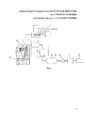
На фиг. 1 изображено устройство подготовки и подачи воздуха в двигатель внутреннего сгорания.In FIG. 1 shows a device for preparing and supplying air to an internal combustion engine.
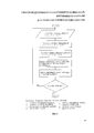
На фиг. 2 представлен алгоритм работы электронного блока управления.In FIG. 2 presents the algorithm of the electronic control unit.
Устройство подготовки и подачи воздуха в двигатель внутреннего сгорания содержит компрессор 1 для сжатия воздуха, накопитель 2 сжатого воздуха, инжектор 3 для вдувания воздуха в цилиндр 4 двигателя внутреннего сгорания, фильтр 5 очистки воздуха, расположенный на входе в компрессор 1, устройство 6 для отделения масла и влаги от воздуха, расположенное на выходе из компрессора 1 и связанное с накопителем 2 сжатого воздуха, устройство 7 для редуцирования давления воздуха, теплообменник 8 для охлаждения воздуха, и подогреватель 9 воздуха, расположенные между накопителем 2 сжатого воздуха и инжектором 3, причем устройство 7 для редуцирования давления воздуха и инжектор 3 связаны с электронным блоком управления 10. На фиг. 1 показан инжектор 3, расположенный в двигателе внутреннего сгорания. На фиг. 1 показаны соединения электронного блока управления 10 с датчиками положения распредвала двигателя, положения коленвала двигателя, температуры охлаждающей жидкости, температуры топлива, давления атмосферного воздуха, положения педали газа, массового расхода воздуха, давления топлива.A device for preparing and supplying air to an internal combustion engine comprises a compressor 1 for compressing air, a
Накопитель 2 сжатого воздуха может быть выполнен с предохранительным клапаном 11 для выпуска воздуха из накопителя 2 при достижении давления воздуха предельно допустимого значения.The
Рассмотрим пример конкретной реализации устройства подготовки и подачи воздуха в двигатель внутреннего сгорания и его работу на грузовом автомобиле КамА3-740 с двигателем мощностью 210 л.с. Для запасания воздуха он сжимается до давления 200 кг/см2 с помощью поршневого компрессора 1 для сжатия воздуха, имеющего ременный привод от двигателя внутреннего сгорания и закачивается в накопитель 2 сжатого воздуха объемом 100 л, выполненный из углепластика. Дополнительно к описываемой в предлагаемом техническом решении функции, сжатый воздух из накопителя 2 сжатого воздуха может быть использован в качестве рабочего тела в тормозной системе автомобиля КАМА3-740. Для этого может быть использован редукционный клапан (на чертеже не показан), снижающий давление воздуха до давления 8 кГс/см2, на которое рассчитан тормозной контур автомобиля. В компрессор 1 для сжатия воздуха воздух поступает из атмосферы, поэтому на входе в компрессор 1 для сжатия воздуха он очищается фильтром 5 очистки воздуха, установленным на впускном отверстии компрессора 1 для сжатия воздуха, для предотвращения попадания этих частиц в цилиндр 4 двигателя внутреннего сгорания, так как это приведет к преждевременному износу поршневых колец и цилиндра двигателя. Частицы масла, попавшие в воздух из-за не идеального уплотнения или износа поршневых колец компрессора 1 для сжатия воздуха, а также атмосферная влага, улавливаются устройством 6 для отделения масла и влаги от воздуха, находящимся на выходе из компрессора 1 для сжатия воздуха. Принцип работы устройства 6 для отделения масла и влаги от воздуха основан на пропускании воздуха через адсорбер влаги в виде силикогеля, помещенного в сосуд. Редуцирование сжатого воздуха перед вдуванием в цилиндр 4 двигателя внутреннего сгорания осуществляют для получения оптимального для конкретного режима работы двигателя внутреннего сгорания давления подаваемого воздуха. В штатном режиме работы в цилиндр 4 двигателя внутреннего сгорания подают воздух под рабочим давлением, которое варьируется в диапазоне значений до 5 кГс/см2, в зависимости от режима работы двигателя. Например для осуществления резкого ускорения двигателя подают воздух под давлением 5 кГс/см2. Для осуществления запуска двигателя воздух подают под давлением 15 кГс/см2. При этом давление на выходе из устройства 7 для редуцирования давления воздуха равно 30 кГс/см2, так как потери давления при прохождении воздуха равны 50%. Устройство 7 для редуцирования давления воздуха представляет из себя газовый редуктор с дистанционным электрическим приводом. Управление приводом устройства 7 для редуцирования давления воздуха осуществляется от электронного блока управления 10. При сжатии компрессором 1 для сжатия воздуха воздух нагревается до 150-200 градусов Цельсия, что снижает его плотность по сравнению с более холодным воздухом, находящимся под таким же давлением. Для увеличения массы воздуха, вдуваемого в цилиндр 4 двигателя внутреннего сгорания при заданном давлении его необходимо охладить. Для охлаждения воздуха используется теплообменник 8 для охлаждения воздуха, проходя через который воздух охлаждается до температуры ниже 100 градусов Цельсия. Теплообменник 8 для охлаждения воздуха охлаждается атмосферным воздухом, выполнен из алюминиевых трубок и пластин и располагается в районе воздухозаборника автомобиля. При эксплуатации автомобиля в условиях холодного климата до разогрева двигателя до штатной температуры применяется подогреватель 9 воздуха. Он предназначен для нагрева воздуха до плюсовой по Цельсию температуры, которая обеспечивает оптимальное образование топливной смеси в цилиндре 4 двигателя внутреннего сгорания. Подогреватель 9 воздуха выполнен в виде трубки, обогреваемой электрическим сопротивлением. Электрическая энергия для этого при работающем двигателе подводится от генератора автомобиля, а до запуска двигателя от аккумулятора. Подогреватель 9 включается по сигналу от электронного блока управления 10. Транспортировка воздуха между перечисленными устройствами осуществляется через трубопровод. Накопитель 2 сжатого воздуха может быть выполнен с предохранительным клапаном 11 для выпуска воздуха, выполненным в виде шарика, прижатого пружиной к седлу с усилием, которое преодолевается напором воздуха в накопителе 2 сжатого воздуха, когда давление воздуха в нем превышает 200 кГс/см2. Это предотвращает превышение давление воздуха в накопителе 2 сжатого воздуха с целью исключить его разрушение. Электронный блок управления 10 представляет из себя микроконтроллер, который получает входные данные, характеризующие режим работы двигателя, с датчиков положения распредвала двигателя, положения коленвала двигателя, температуры охлаждающей жидкости, температуры топлива, давления атмосферного воздуха, положения педали газа, массового расхода воздуха, давления топлива.Consider an example of a specific implementation of a device for preparing and supplying air to an internal combustion engine and its operation on a KamA3-740 truck with a 210 hp engine. To store air, it is compressed to a pressure of 200 kg / cm 2 using a piston compressor 1 for compressing air, which has a belt drive from an internal combustion engine and is pumped into a
По заданной программе управления двигателем, алгоритм части которой приведен на фиг. 2, микроконтроллер производит вычисления с использованием в качестве переменных входные данные, полученные с датчиков, и выдает управляющие сигналы на коммутаторы электроприводов инжектора 3 для вдувания воздуха в цилиндр 4 и устройства 7 для редуцирования давления воздуха.According to a predetermined engine control program, an algorithm of a part of which is shown in FIG. 2, the microcontroller performs calculations using the input data from the sensors as variables and provides control signals to the commutators of the electric drives of the
Рассмотрим устройство подготовки и подачи воздуха в двигатель внутреннего сгорания в работе. Перед запуском двигателя внутреннего сгорания в накопителе 2 сжатого воздуха находится воздух под давлением 200 кГс/см2, запасенный с предыдущего сеанса работы двигателя. При повороте ключа зажигания происходит подача воздуха из накопителя 2 сжатого воздуха в цилиндр 4 двигателя внутреннего сгорания под давлением 15 кГс/см2, благодаря тому, что устройство редуцирования получает сигнал от электронного блока управления 10 на редуцирование воздуха до этого давления при запуске двигателя. Это приводит поршень и весь кривошипно-шатунный механизм в движение. Далее, синхронизированно, с определенным отставанием, запускаются рабочие такты двигателя, такие как выпуск воздуха из цилиндра 4 двигателя внутреннего сгорания, вдувание воздуха под рабочим давлением, впрыск топливной смеси, ее сжатие и воспламенение. Давление подаваемого воздуха перед впрыском топлива снижается до рабочего, с помощью устройства 7 для редуцирования давления воздуха. Одновременно с запуском двигателя производится запуск компрессора 1 для сжатия воздуха. Компрессор 1 для сжатия воздуха засасывает воздух из атмосферы, при этом воздух очищается фильтром 5 очистки воздуха, сжимается компрессором 1 для сжатия воздуха, очищается от влаги и масла устройством 6 для отделения масла и влаги и поступает в накопитель 2 сжатого воздуха непрерывно до достижения в нем давления воздуха 200 кГс/см2. После достижения этого давления компрессор 1 для сжатия воздуха отключается и запускается вновь только при падении давления воздуха в накопителе 2 сжатого воздуха ниже 150 кГс/см2. Из накопителя 2 сжатого воздуха воздух протекает по трубопроводу, через устройство 7 для редуцирования давления воздуха, теплообменник 8 для охлаждения воздуха и подогреватель 9 воздуха. Вытекание воздуха из этой замкнутой системы контролируется инжектором 3 для вдувания воздуха в цилиндр 4. Открытие инжектора 3 для вдувания воздуха в цилиндр 4 двигателя внутреннего сгорания управляется электронным блоком управления 10, который осуществляет вдувание воздуха в цилиндр 4 тактами, синхронизированными с рабочими тактами двигателя внутреннего сгорания. Объем воздуха, подаваемый в цилиндр 4 двигателя внутреннего сгорания определяется временем открытия инжектора 3 для вдувания воздуха в цилиндр 4 двигателя внутреннего сгорания и давлением воздуха перед инжектором 3 для вдувания воздуха в цилиндр 4 двигателя внутреннего сгорания, которое поддерживается с помощью устройства 7 для редуцирования давления воздуха. При нажатии водителя на педаль газа электронный блок управления 10 осуществляет пропорциональное степени нажатия педали увеличение времени открытия инжектора 3 для вдувания воздуха в цилиндр 4 двигателя внутреннего сгорания и увеличение давления воздуха перед инжектором 3 для вдувания большего количества воздуха в цилиндр 4 двигателя внутреннего сгорания.Consider a device for preparing and supplying air to an internal combustion engine in operation. Before starting the internal combustion engine in the
В традиционных двигателях с турбокомпрессором раскручивание турбины осуществляется выхлопными газами и ее обороты и производительность турбокомпрессора связаны с оборотами коленвала не напрямую, а через выхлопную систему. Поэтому при резком нажатии на педаль газа производительности турбокомпрессора в начальный момент времени бывает не достаточно для обеспечения пропорционального нажатию педали газа увеличения количества подаваемого в цилиндр воздуха. В результате возникает эффект так называемых "турболага" или "турбоямы", заключающийся в отсутствии в этот момент времени, пока выхлоп не дойдет до турбины и не раскрутит ее, ускорения двигателя пропорционального нажатию на педаль газа. В выбранном прототипе этот недостаток частично устранен. Однако в прототипе отсутствует устройство для редуцирования воздуха, поэтому диапазон значений расхода воздуха, а также точность и скорость регулировки этого значения, необходимые для быстрой реакции двигателя на нажатие педали газа, ниже, чем в предлагаемом техническом решении. В предлагаемом техническом решении благодаря применению накопителя 2 сжатого воздуха и устройства 7 для редуцирования давления воздуха в любой момент времени возможна подача воздуха в большом диапазоне значений его расхода в цилиндр 4 двигателя внутреннего сгорания, что исключает возникновение "турбоямы".In traditional engines with a turbocharger, the turbine spins up with exhaust gases and its speed and turbocharger performance are not directly related to the crankshaft speed, but through the exhaust system. Therefore, when the gas pedal is abruptly pressed, the performance of the turbocharger at the initial time is not enough to ensure that the amount of air supplied to the cylinder increases proportionally to the gas pedal. As a result, the effect of the so-called "turbolag" or "turbojam" arises, which consists in the absence at this point in time, until the exhaust reaches the turbine and spins it, the acceleration of the engine is proportional to pressing the gas pedal. In the selected prototype, this drawback is partially eliminated. However, in the prototype there is no device for air reduction, therefore, the range of air flow values, as well as the accuracy and speed of adjustment of this value, necessary for a quick reaction of the engine to pressing the gas pedal, are lower than in the proposed technical solution. In the proposed technical solution, due to the use of a compressed
Технический результат полезной модели достигается благодаря:The technical result of the utility model is achieved due to:
- применению устройства 7 для редуцирования давления воздуха, позволяющего осуществлять подачу воздуха в цилиндр 4 двигателя внутреннего сгорания с оптимальным точно дозированным расходом;- the use of a
- применению теплообменника 8 для охлаждения воздуха и подогревателя 9 воздуха, позволяющих осуществлять подачу воздуха оптимальной температуры в цилиндр 4 двигателя внутреннего сгорания;- the use of a
- применению фильтра 5 очистки воздуха и устройства 6 для отделения масла и влаги от воздуха, позволяющих осуществлять подачу в цилиндр 4 двигателя внутреннего сгорания воздуха без примесей, снижающих качество воспламенения топливно-воздушной смеси;- the use of an
- применению непосредственного вдувания воздуха через инжектор 3 в цилиндр 4 двигателя внутреннего сгорания, исключая энергетические потери на расширение в коллекторе или других промежуточных объемах.- the use of direct injection of air through the
Предложенное техническое решение повышает эффективность подготовки и подачи воздуха в цилиндр двигателя внутреннего сгорания, тем самым повышая эффективность работы двигателя внутреннего сгоранияThe proposed technical solution improves the efficiency of the preparation and supply of air to the cylinder of an internal combustion engine, thereby increasing the efficiency of the internal combustion engine
Дополнительным преимуществом по сравнению с прототипом в предлагаемом устройстве подготовки и подачи воздуха в двигатель внутреннего сгорания является возможность осуществления запуска двигателя сжатым воздухом из накопителя 2 сжатого воздуха.An additional advantage compared with the prototype in the proposed device for the preparation and supply of air to the internal combustion engine is the ability to start the engine with compressed air from the
Claims (2)
Priority Applications (1)
| Application Number | Priority Date | Filing Date | Title |
|---|---|---|---|
| RU2015130283U RU167883U1 (en) | 2015-07-22 | 2015-07-22 | A device for preparing and supplying air to an internal combustion engine. |
Applications Claiming Priority (1)
| Application Number | Priority Date | Filing Date | Title |
|---|---|---|---|
| RU2015130283U RU167883U1 (en) | 2015-07-22 | 2015-07-22 | A device for preparing and supplying air to an internal combustion engine. |
Publications (1)
| Publication Number | Publication Date |
|---|---|
| RU167883U1 true RU167883U1 (en) | 2017-01-11 |
Family
ID=58451318
Family Applications (1)
| Application Number | Title | Priority Date | Filing Date |
|---|---|---|---|
| RU2015130283U RU167883U1 (en) | 2015-07-22 | 2015-07-22 | A device for preparing and supplying air to an internal combustion engine. |
Country Status (1)
| Country | Link |
|---|---|
| RU (1) | RU167883U1 (en) |
Cited By (1)
| Publication number | Priority date | Publication date | Assignee | Title |
|---|---|---|---|---|
| CN111058938A (en) * | 2019-12-27 | 2020-04-24 | 中国第一汽车股份有限公司 | In-cylinder tumble flow disturbance system and automobile |
Citations (8)
| Publication number | Priority date | Publication date | Assignee | Title |
|---|---|---|---|---|
| SU177227A1 (en) * | Харьковский завод транспортного машиностроени | DEVICE FOR IMPROVEMENT OF DIESEL-GENERATOR ADAPTATION WITH GAS TURBINE SUPERCHARGING | ||
| RU2008454C1 (en) * | 1990-03-21 | 1994-02-28 | Юрий Михайлович Шмаков | Method of operation of two-stroke internal combustion engine |
| RU2192550C1 (en) * | 2001-03-02 | 2002-11-10 | Морозов Валерий Владимирович | Method of and device for combustion of working mixtures in above-piston space of internal combustion engine |
| US20060124085A1 (en) * | 2003-02-12 | 2006-06-15 | D-J Engineering Inc. | Air injection engine |
| RU2305195C1 (en) * | 2006-04-14 | 2007-08-27 | Игорь Васильевич Боев | Axial piston engine |
| RU2392457C2 (en) * | 2005-02-24 | 2010-06-20 | Кнорр-Бремзе Зюстеме Фюр Нутцфарцойге Гмбх | Device for supplying plenum air to piston turbo-charged internal combustion engine, and its operating method |
| US20120240909A1 (en) * | 2011-03-25 | 2012-09-27 | Stephen Mark Geyer | Methods and systems for controlling transient engine response |
| RU150916U1 (en) * | 2013-04-09 | 2015-03-10 | ФОРД ГЛОУБАЛ ТЕКНОЛОДЖИЗ, ЭлЭлСи | INFLATED COMBUSTION ENGINE |
-
2015
- 2015-07-22 RU RU2015130283U patent/RU167883U1/en active IP Right Revival
Patent Citations (8)
| Publication number | Priority date | Publication date | Assignee | Title |
|---|---|---|---|---|
| SU177227A1 (en) * | Харьковский завод транспортного машиностроени | DEVICE FOR IMPROVEMENT OF DIESEL-GENERATOR ADAPTATION WITH GAS TURBINE SUPERCHARGING | ||
| RU2008454C1 (en) * | 1990-03-21 | 1994-02-28 | Юрий Михайлович Шмаков | Method of operation of two-stroke internal combustion engine |
| RU2192550C1 (en) * | 2001-03-02 | 2002-11-10 | Морозов Валерий Владимирович | Method of and device for combustion of working mixtures in above-piston space of internal combustion engine |
| US20060124085A1 (en) * | 2003-02-12 | 2006-06-15 | D-J Engineering Inc. | Air injection engine |
| RU2392457C2 (en) * | 2005-02-24 | 2010-06-20 | Кнорр-Бремзе Зюстеме Фюр Нутцфарцойге Гмбх | Device for supplying plenum air to piston turbo-charged internal combustion engine, and its operating method |
| RU2305195C1 (en) * | 2006-04-14 | 2007-08-27 | Игорь Васильевич Боев | Axial piston engine |
| US20120240909A1 (en) * | 2011-03-25 | 2012-09-27 | Stephen Mark Geyer | Methods and systems for controlling transient engine response |
| RU150916U1 (en) * | 2013-04-09 | 2015-03-10 | ФОРД ГЛОУБАЛ ТЕКНОЛОДЖИЗ, ЭлЭлСи | INFLATED COMBUSTION ENGINE |
Cited By (1)
| Publication number | Priority date | Publication date | Assignee | Title |
|---|---|---|---|---|
| CN111058938A (en) * | 2019-12-27 | 2020-04-24 | 中国第一汽车股份有限公司 | In-cylinder tumble flow disturbance system and automobile |
Similar Documents
| Publication | Publication Date | Title |
|---|---|---|
| CN102308063B (en) | Split cycle reciprocating piston engine | |
| US7958872B1 (en) | Airless engine with gas and water recycling | |
| RU2622457C1 (en) | Internal combustion engine based on isothermal compression, its operating and management methods | |
| CN102418626B (en) | Integrated exhaust gas recirculation and charge cooling system | |
| WO2003001046A3 (en) | Method for operating an internal combustion engine | |
| RU2445477C2 (en) | Internal combustion engine | |
| JP7147229B2 (en) | Waste heat utilization system | |
| RU2014137886A (en) | PISTON INTERNAL COMBUSTION ENGINE AND METHOD FOR FUNCTIONING A PISTON INTERNAL COMBUSTION ENGINE | |
| RU167883U1 (en) | A device for preparing and supplying air to an internal combustion engine. | |
| WO2017014668A1 (en) | Device and method for supplying air to an internal combustion engine | |
| CN101852130A (en) | Dual media hybrid engine | |
| RU2702072C2 (en) | Method (embodiments) and system for extracting heat energy from exhaust gases of engine cylinders | |
| UA155578U (en) | Device for supplying air to the internal combustion engine | |
| RU2814906C1 (en) | Ice gas turbine supercharging system with device for overcoming "turbo lag" | |
| US20070277793A1 (en) | Method for operating an internal combustion engine | |
| CN104100362A (en) | Engine/generator water circulation system for reducing exhaust pollutant emission | |
| JP2019065731A (en) | Engine intake system | |
| WO2017091098A1 (en) | Internal combustion engine operation method | |
| CN205714414U (en) | A kind of Vehicular exhaust energy recycling device | |
| RU180161U1 (en) | DIESEL FUEL SUPPLY SYSTEM | |
| SU1055897A1 (en) | Ic engine operation process | |
| RU176215U1 (en) | SECONDARY VEHICLE CIRCUIT OF ICE VEHICLE | |
| CN207261125U (en) | Manifold injected engine and automobile | |
| WO2015006211A1 (en) | Turbocharged single cylinder internal combustion engine using an air capacitor | |
| CN121079494A (en) | Control method and system for a charge spark ignition internal combustion engine for purging a charge air cooler |
Legal Events
| Date | Code | Title | Description |
|---|---|---|---|
| MM9K | Utility model has become invalid (non-payment of fees) |
Effective date: 20170723 |
|
| NF9K | Utility model reinstated |
Effective date: 20181113 |