RU166375U1 - GAS EXTINGUISHING MODULE - Google Patents
GAS EXTINGUISHING MODULE Download PDFInfo
- Publication number
- RU166375U1 RU166375U1 RU2015151032/12U RU2015151032U RU166375U1 RU 166375 U1 RU166375 U1 RU 166375U1 RU 2015151032/12 U RU2015151032/12 U RU 2015151032/12U RU 2015151032 U RU2015151032 U RU 2015151032U RU 166375 U1 RU166375 U1 RU 166375U1
- Authority
- RU
- Russia
- Prior art keywords
- housing
- module
- fire extinguishing
- rod
- locking
- Prior art date
Links
- 230000009172 bursting Effects 0.000 claims abstract description 13
- 239000003795 chemical substances by application Substances 0.000 claims abstract description 12
- 230000011664 signaling Effects 0.000 claims abstract description 5
- 230000003993 interaction Effects 0.000 claims abstract 2
- 238000004891 communication Methods 0.000 description 10
- 230000005540 biological transmission Effects 0.000 description 8
- 238000012423 maintenance Methods 0.000 description 8
- 239000012528 membrane Substances 0.000 description 8
- 238000013461 design Methods 0.000 description 6
- 238000009434 installation Methods 0.000 description 6
- 238000000034 method Methods 0.000 description 5
- 230000008569 process Effects 0.000 description 5
- 238000012544 monitoring process Methods 0.000 description 4
- 239000006185 dispersion Substances 0.000 description 3
- 239000011521 glass Substances 0.000 description 3
- 230000000007 visual effect Effects 0.000 description 3
- 230000006378 damage Effects 0.000 description 2
- 238000010304 firing Methods 0.000 description 2
- 239000007788 liquid Substances 0.000 description 2
- 229910052751 metal Inorganic materials 0.000 description 2
- 239000002184 metal Substances 0.000 description 2
- 230000000737 periodic effect Effects 0.000 description 2
- 229920006395 saturated elastomer Polymers 0.000 description 2
- 230000009471 action Effects 0.000 description 1
- 229910052782 aluminium Inorganic materials 0.000 description 1
- XAGFODPZIPBFFR-UHFFFAOYSA-N aluminium Chemical compound [Al] XAGFODPZIPBFFR-UHFFFAOYSA-N 0.000 description 1
- 230000008901 benefit Effects 0.000 description 1
- 230000015572 biosynthetic process Effects 0.000 description 1
- 230000002925 chemical effect Effects 0.000 description 1
- 239000002131 composite material Substances 0.000 description 1
- 230000000694 effects Effects 0.000 description 1
- 239000011888 foil Substances 0.000 description 1
- 238000007689 inspection Methods 0.000 description 1
- 230000007246 mechanism Effects 0.000 description 1
- 150000002739 metals Chemical class 0.000 description 1
- GTLACDSXYULKMZ-UHFFFAOYSA-N pentafluoroethane Chemical compound FC(F)C(F)(F)F GTLACDSXYULKMZ-UHFFFAOYSA-N 0.000 description 1
- 239000004033 plastic Substances 0.000 description 1
- 229920003023 plastic Polymers 0.000 description 1
- 230000008092 positive effect Effects 0.000 description 1
- 230000009467 reduction Effects 0.000 description 1
- 230000000284 resting effect Effects 0.000 description 1
- 238000005476 soldering Methods 0.000 description 1
- 239000007921 spray Substances 0.000 description 1
- 238000012360 testing method Methods 0.000 description 1
- 230000001960 triggered effect Effects 0.000 description 1
- 238000003466 welding Methods 0.000 description 1
Images
Classifications
-
- A—HUMAN NECESSITIES
- A62—LIFE-SAVING; FIRE-FIGHTING
- A62C—FIRE-FIGHTING
- A62C35/00—Permanently-installed equipment
- A62C35/02—Permanently-installed equipment with containers for delivering the extinguishing substance
Landscapes
- Health & Medical Sciences (AREA)
- Public Health (AREA)
- Business, Economics & Management (AREA)
- Emergency Management (AREA)
- Fire-Extinguishing By Fire Departments, And Fire-Extinguishing Equipment And Control Thereof (AREA)
Abstract
1. Модуль газового пожаротушения, включающий корпус, заполненный огнетушащим веществом, запорно-пусковое устройство, узел крепления корпуса, отличающийся тем, что он снабжен предохранительным клапаном с разрывной мембраной и датчиком давления в корпусе, узел крепления корпуса состоит из цилиндрического стержня для взаимодействия с монтажным кронштейном с фиксатором, стержень одним торцом укреплен на корпусе напротив запорно-пускового устройства, а со стороны противоположного торца на его цилиндрической поверхности выполнена кольцевая канавка и две параллельные друг другу лыски, в предохранительном клапане выполнен перепускной канал для сообщения полости корпуса с атмосферой, при этом разрывная мембрана установлена с возможностью перекрытия перепускного канала и выполнена в форме части сферы, обращенной выпуклой частью к атмосферному выходу.2. Модуль по п. 1, отличающийся тем, что датчик давления выполнен в виде электроконтактного сигнализирующего манометра.1. The gas fire extinguishing module, comprising a housing filled with a fire extinguishing agent, a locking and starting device, a housing attachment unit, characterized in that it is equipped with a safety valve with a bursting disc and a pressure sensor in the housing, the housing attachment unit consists of a cylindrical rod for interaction with the mounting with a bracket, the rod is fixed with one end on the housing opposite the locking-starting device, and rings are made on the cylindrical surface from the side of the opposite end I groove and two parallel flats, in the relief valve passageway adapted to communicate with the atmosphere of the housing, wherein the rupture disc is arranged to overlap the passageway and is in the form of a sphere, the convex part facing to atmospheric vyhodu.2. The module according to claim 1, characterized in that the pressure sensor is made in the form of an electrical contact signaling pressure gauge.
Description
Полезная модель относится к противопожарной технике, а более конкретно к автоматизированным устройствам объемного тушения посредством газообразного огнегасительного вещества, находящегося в резервуаре под постоянным давлением, и может быть использована для объемного тушения пожаров класса А, В и С и электрооборудования.The utility model relates to fire fighting equipment, and more particularly to automated volumetric extinguishing devices by means of a gaseous extinguishing agent located in a tank under constant pressure, and can be used for volumetric extinguishing of class A, B and C fires and electrical equipment.
Из уровня техники известно запорно-пусковое устройство огнетушителя, включающее запорное устройство, и предохранительное устройство диафрагменного типа, состоящее из диафрагмы и пробки, и имеет возможность срабатывать при достижении предельного установленного давления, причем диафрагменное устройство прикреплено методом сварки, или пайки, или резьбового соединения, см. патент на полезную модель, RU, кл. А62С 13/76, №54520, опубликован 10.07.2006. Недостатком известного устройства является большой разброс давления прорыва диафрагмы, обусловленный плоским видом поверхности диафрагмы, работающей на срез, что существенно снижает безопасность эксплуатации устройства.It is known from the prior art that a fire extinguisher’s locking and starting device, including a locking device, and a diaphragm type safety device, consisting of a diaphragm and a plug, can be triggered when the set pressure is reached, the diaphragm device being attached by welding or soldering or threaded connection, see patent for utility model, RU, cl. А62С 13/76, No. 5420, published July 10, 2006. A disadvantage of the known device is the large dispersion of the pressure of the breakthrough of the diaphragm, due to the flat view of the surface of the diaphragm working on a slice, which significantly reduces the safety of operation of the device.
Известно устройство газового пожаротушения, включающее корпус, оснащенный кронштейном для крепления устройства на опорной поверхности, см. пат. RU, кл. А62С 35/00, №2495695, опубликован 20.10.2013. Недостатком известного устройства является неудобство его монтажа посредством кронштейна на стене или потолке, что сопряжено с опасностью падения.A device for gas fire extinguishing, including a housing equipped with a bracket for mounting the device on a supporting surface, see US Pat. RU, cl. А62С 35/00, No. 2495695, published October 20, 2013. A disadvantage of the known device is the inconvenience of its installation by means of an bracket on a wall or ceiling, which is fraught with the danger of falling.
Известен автоматический огнетушитель, содержащий емкость для огнетушащего вещества, систему выпуска огнетушащего вещества, пусковой механизм, включающий термочувствительный элемент и боек, термочувствительный элемент содержит корпус, разрушаемый под воздействием заданной температуры, а боек оборудован пружиной и уступом, контактирующим с подпружиненным фиксатором, опирающимся на корпус термочувствительного элемента, выполненного в виде стеклянной колбы, заполненной жидкостью с большим коэффициентом линейного расширения, при этом термочувствительный элемент дополнительно снабжен электронагревателем, связанным через пульт управления с пожарным извещателем, см. пат. RU, кл. А62С 35/68, №2104724, опубликован 20.02.1998. Автоматический огнетушитель согласно прототипу характеризуется простотой конструкции огнетушителя и повышенной надежностью его работы. Данный известный огнетушитель принят в качестве прототипа, как наиболее близкий по технической сущности и достигаемому результату аналог.Known automatic fire extinguisher containing a container for a fire extinguishing agent, a fire extinguishing agent release system, a trigger mechanism including a heat-sensitive element and a firing pin, a heat-sensitive element contains a housing that is destroyed under the influence of a given temperature, and the firing pin is equipped with a spring and a ledge in contact with a spring-loaded latch resting on the housing a thermosensitive element made in the form of a glass flask filled with a liquid with a large coefficient of linear expansion, while the temperature-sensitive element is additionally equipped with an electric heater connected via a control panel to a fire detector, see US Pat. RU, cl. А62С 35/68, No. 2104724, published on 02.20.1998. The automatic fire extinguisher according to the prototype is characterized by the simplicity of the design of the fire extinguisher and the increased reliability of its operation. This well-known fire extinguisher is adopted as a prototype, as the closest analogue in technical essence and achieved result.
Недостатком прототипа является неудобная конструкция узла крепления огнетушителя, вынуждающая при подвешивании его к потолку долгое время удерживать огнетушитель навесу. Мембранный узел известного автоматического огнетушителя включает плоскую мембрану, которая при вскрытии работает на срез, при этом разброс давления вскрытия мембраны может составлять более 20%, что требует повышенного запаса прочности корпуса и утяжеляет его. Кроме того, огнетушитель согласно прототипу не оснащен средствами обратной связи и требует в процессе его эксплуатации постоянного визуального контроля в т.ч. и за сроками проведения очередного технического обслуживания. Указанные недостатки прототипа существенно снижают его эксплуатационные характеристики, к числу которых следует отнести трудоемкость при монтаже и затратность при эксплуатации, что в конечном итоге ограничивает область применения изделия.The disadvantage of the prototype is the inconvenient design of the attachment point of the fire extinguisher, forcing it to hang the canopy fire extinguisher for a long time when hanging it from the ceiling. The membrane unit of the known automatic fire extinguisher includes a flat membrane, which, when opened, works for shear, while the dispersion of the opening pressure of the membrane can be more than 20%, which requires an increased margin of safety of the body and makes it heavier. In addition, the fire extinguisher according to the prototype is not equipped with feedback means and requires constant visual control, including and for the timing of the next maintenance. These disadvantages of the prototype significantly reduce its operational characteristics, which include the complexity of installation and the cost of operation, which ultimately limits the scope of the product.
Полезная модель направлена на достижение технического результата, который выражается в упрощении процессов монтажа/демонтажа модуля на объекте и его обслуживания в эксплуатации. В конечном итоге указанный технический результат позволяет повысить удобство и эффективность пользования модулем газового пожаротушения. В полезной модели максимально сохранены все положительные свойства прототипа, наиболее важными из которых являются надежность и быстрота срабатывания огнетушителя.The utility model is aimed at achieving a technical result, which is expressed in simplifying the processes of mounting / dismounting the module at the facility and its maintenance in operation. Ultimately, the specified technical result improves the convenience and efficiency of using the gas fire extinguishing module. In the utility model, all the positive properties of the prototype are maximally preserved, the most important of which are the reliability and speed of the fire extinguisher.
Указанный технический результат достигается тем, что модуль газового пожаротушения, включающий корпус, заполненный огнетушащим веществом, запорно-пусковое устройство, узел крепления корпуса и средство связи с удаленным пунктом контроля, отличается от прототипа тем, что он снабжен предохранительным клапаном с разрывной мембраной и датчиком давления в корпусе. Узел крепления корпуса состоит из цилиндрического стержня и взаимодействующего с ним монтажного кронштейна с фиксатором. Цилиндрический стержень одним торцом укреплен на корпусе напротив запорно-пускового устройства, а со стороны противоположного торца на его цилиндрической поверхности выполнена кольцевая канавка и две параллельные друг другу лыски. Монтажный кронштейн выполнен с возможностью крепления к поверхности защищаемого объекта и имеет несущую поверхность, в которой выполнена фигурная прорезь в виде сквозного отверстия и паза, соединяющего отверстие с краем несущей поверхности, при этом диаметр отверстия соответствует диаметру кольцевой канавки, а ширина паза соответствует расстоянию между лысками. Фиксатор выполнен в виде штифта, устанавливаемого на несущей поверхности с возможностью предотвращения поворота стержня в отверстии кронштейна. В предохранительном клапане выполнен перепускной канал для сообщения полости корпуса с атмосферой, при этом разрывная мембрана установлена с возможностью перекрытия перепускного канала и выполнена в форме части сферы, обращенной выпуклой частью к атмосферному выходу. Средство связи с удаленным пунктом контроля выполнено в виде электронного блока беспроводной передачи данных, соединенного с датчиком давления в корпусе.The specified technical result is achieved in that the gas fire extinguishing module, comprising a housing filled with a fire extinguishing agent, a locking and starting device, a housing attachment unit and a communication device with a remote control point, differs from the prototype in that it is equipped with a safety valve with a bursting disc and a pressure sensor in the case. The housing attachment unit consists of a cylindrical rod and a mounting bracket with a latch interacting with it. A cylindrical rod is fixed with one end on the housing opposite the locking-starting device, and from the side of the opposite end, an annular groove and two parallel flats are made on its cylindrical surface. The mounting bracket is adapted to be attached to the surface of the protected object and has a bearing surface in which a curly slot is made in the form of a through hole and a groove connecting the hole to the edge of the bearing surface, the diameter of the hole corresponding to the diameter of the annular groove and the width of the groove corresponding to the distance between the flanges . The latch is made in the form of a pin mounted on a bearing surface with the possibility of preventing the rotation of the rod in the hole of the bracket. In the safety valve, a bypass channel is made for communication of the housing cavity with the atmosphere, while the bursting membrane is installed with the possibility of overlapping the bypass channel and is made in the form of a part of a sphere facing the convex part to the atmospheric outlet. The communication tool with the remote control point is made in the form of an electronic unit for wireless data transmission connected to a pressure sensor in the housing.
Оптимальным с точки зрения достижения указанного технического результата является выполнение датчика давления в виде электроконтактного сигнализирующего манометра. Предпочтительно электронный блок беспроводной передачи данных включает контролер с функцией таймера отсчета срока очередного технического обслуживания, блок питания, передатчик сетей мобильной радиотелефонной связи с антенной, при этом передатчик сетей мобильной радиотелефонной связи функционирует в диапазоне стандарта GSM-900/1800 и в режиме GPRS.Optimal from the point of view of achieving the specified technical result is the implementation of the pressure sensor in the form of an electrical contact signaling pressure gauge. Preferably, the electronic wireless data transmission unit includes a controller with a timer for the next maintenance period, a power supply unit, a transmitter for mobile radiotelephone networks with an antenna, while the transmitter for mobile radiotelephone networks operates in the range of the GSM-900/1800 standard and in GPRS mode.
Автономные газовые огнетушители являются приборами постоянной готовности, а также многократного использования, чем и обусловлена необходимость их периодического монтажа и демонтажа на объекте с целью переснаряжения и постоянного контроля состояния.Autonomous gas fire extinguishers are devices of constant readiness, as well as reusable, which necessitates their periodic installation and dismantling at the facility for the purpose of re-equipping and constant monitoring of the condition.
В основу полезной модели положен принцип максимального упрощения и снижения трудоемкости процессов установки, эксплуатации и инспекции модуля газового пожаротушения на защищаемом объекте. Корпус модуля составляет основную часть его веса. Снижение веса корпуса существенно облегчает процессы монтажа и перемещения, и возможно за счет снижения предельного давления в нем. Таким образом, величина давления в корпусе является важнейшей характеристикой модуля газового пожаротушения.The utility model is based on the principle of maximum simplification and reduction of the complexity of the installation, operation and inspection of the gas fire extinguishing module at the protected facility. The module case makes up the bulk of its weight. Reducing the weight of the housing greatly facilitates the processes of installation and movement, and possibly by reducing the maximum pressure in it. Thus, the pressure in the housing is the most important characteristic of a gas fire extinguishing module.
Применение в конструкции модуля составного узла крепления позволяет простым движением монтировать и демонтировать модуль под потолком. Поскольку монтажный кронштейн стационарно крепится на объекте, независимо от корпуса модуля, конструкция последнего максимально облегчена. Узел крепления унифицирован, поэтому возможна замена одного модуля на другой, без переустановки монтажного кронштейна. Фиксатор при взаимодействии с цилиндрическим стержнем образует кинематический замок, который несмотря на простоту конструкции и установки надежно удерживает корпус модуля от перемещения.The use of a composite mount assembly in the module design allows for simple mounting and dismounting of the module under the ceiling. Since the mounting bracket is permanently mounted on the object, regardless of the module case, the design of the latter is made as light as possible. The mounting unit is unified, so it is possible to replace one module with another without reinstalling the mounting bracket. The latch, when interacting with a cylindrical rod, forms a kinematic lock, which, despite the simplicity of design and installation, reliably keeps the module housing from moving.
Оснащение запорно-пускового устройства предохранительным клапаном с разрывной мембраной существенно увеличивает безопасность эксплуатации модуля и улучшает его массово-габаритные характеристики, а выполнение разрывной мембраны в форме части сферы значительно усиливает этот эффект. Предохранительный клапан предотвращает несанкционированное увеличение давления в корпусе выше определенной величины, а наличие выпуклой разрывной мембраны обеспечивает точность и своевременность срабатывания клапана.Equipping the shut-off and starting device with a safety valve with a bursting disc significantly increases the operational safety of the module and improves its mass-dimensional characteristics, and the implementation of a bursting disc in the form of a part of a sphere greatly enhances this effect. The safety valve prevents unauthorized pressure increase in the housing above a certain value, and the presence of a convex bursting disc ensures the accuracy and timeliness of the valve.
Текущий визуальный контроль за величиной давления в корпусе осуществляется путем установки датчика давления. При этом критическим является также и понижение давления в корпусе, которое может свидетельствовать о разгерметизации корпуса. Визуальный контроль, даже периодический, весьма трудоемок, поэтому конструкцией предусмотрено использование в качестве датчика давления электроконтактного сигнализирующего манометра, показания которого передаются на удаленный пункт контроля. Средство связи обеспечивает беспроводную передачу показаний манометра в виде CMC сообщений с необходимыми комментариями. Электронный блок выполняет также ряд дополнительных функций, облегчающих контроль за модулем. Дистанционный контроль параметров модуля газового пожаротушения в совокупности с автоматизированным извещением соответствующих служб, в том числе и о сроках очередного технического обслуживания, позволяет существенно упростить процесс эксплуатации и снизить соответствующие трудозатраты за счет исключения необходимости инспектирования модуля непосредственно на объекте.Current visual control of the pressure in the housing is carried out by installing a pressure sensor. At the same time, a decrease in pressure in the housing is also critical, which may indicate a depressurization of the housing. Visual control, even periodic, is very laborious, therefore, the design provides for the use of an electrocontact signaling pressure gauge as a pressure sensor, the readings of which are transmitted to a remote control point. The communication tool provides wireless transmission of pressure gauge readings in the form of CMC messages with the necessary comments. The electronic unit also performs a number of additional functions that facilitate monitoring of the module. Remote monitoring of the parameters of the gas fire extinguishing module, together with the automated notification of the relevant services, including the timing of the next maintenance, can significantly simplify the operation process and reduce the corresponding labor costs by eliminating the need to inspect the module directly at the facility.
Конструктивная схема модуля газового пожаротушения согласно полезной модели максимально повышает его автономность и надежность в условиях многолетнего использования. Модуль рекомендован к применению в любых помещениях, его удобство и надежность подтверждены испытаниями.The structural scheme of the gas fire extinguishing module according to the utility model maximizes its autonomy and reliability in conditions of many years of use. The module is recommended for use in any room, its convenience and reliability are confirmed by tests.
Таким образом, все отличительные от прототипа признаки модуля газового пожаротушения направлены на получение и являются достаточными для достижения технического результата, а именно упрощение процессов монтажа/демонтажа модуля на объекте и его обслуживания в эксплуатации, что, в свою очередь, позволяет повысить удобство и эффективность пользования модулем газового пожаротушения.Thus, all the signs of a gas fire extinguishing module that are distinct from the prototype are aimed at obtaining and are sufficient to achieve a technical result, namely, simplification of the process of mounting / dismounting the module at the facility and its maintenance in operation, which, in turn, improves the convenience and efficiency of use gas fire extinguishing module.
Модуль газового пожаротушения, характеризующийся описанной совокупностью существенных признаков, является новым и промышленно применимым.The gas fire extinguishing module, characterized by the described set of essential features, is new and industrially applicable.
Техническое решение иллюстрировано чертежами.The technical solution is illustrated by drawings.
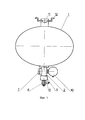
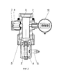
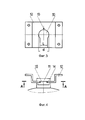
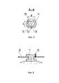
На фиг. 1 изображен общий вид модуля газового пожаротушения; фиг. 2 - запорно-пусковое устройство с предохранительным клапаном и датчиком давления; фиг. 3 - монтажный кронштейн узла крепления корпуса с фиксатором; фиг. 4 - узел крепления корпуса в штатном положении; фиг. 5 - разрез А-А на фиг. 4; фиг. 6 - узел крепления с фиксатором в разрезе.In FIG. 1 shows a general view of a gas fire extinguishing module; FIG. 2 - locking and starting device with safety valve and pressure sensor; FIG. 3 - mounting bracket of the housing attachment unit with a latch; FIG. 4 - housing attachment unit in the normal position; FIG. 5 is a section AA in FIG. four; FIG. 6 - section of the mount with the clamp in the context.
Модуль газового пожаротушения содержит корпус 1 в форме эллипсоида вращения, заполненный газообразным огнегасительным веществом, находящимся под избыточным по отношению к окружающей среде давлением. В качестве огнегасительного вещества использован хладон 125 или хладон 227 под давлением насыщенных паров 15 бар.The gas extinguishing module contains a
В нижней части корпуса 1 посредством резьбового соединения смонтировано запорно-пусковое устройство 2, включающее запорный тарельчатый клапан 3, опирающийся на разрушаемую стеклянную колбу 4, распылитель 5, пиротолкатель 6.In the lower part of the
Запорно-пусковое устройство 2 модуля газового пожаротушения оснащено предохранительным клапаном 7, в котором выполнен перепускной канал 8, сообщающий внутреннюю полость корпуса 1 с атмосферой. В перепускном канале 8 предохранительного клапана 7 установлена разрывная мембрана 9, выполненная из алюминиевой фольги и герметично перекрывающая проходное сечение перепускного канала 8. Рабочая поверхность разрывной мембраны 9 выполнена в форме части сферы, обращенной выпуклой частью к выходному (атмосферному) участку перепускного канала 8 предохранительного клапана 7.The locking and
На запорно-пусковом устройстве 2 модуля газового пожаротушения также смонтирован датчик 10 измерения уровня давления в корпусе 1. Датчик 10 представляет собой стрелочный или электронный сигнализирующий манометр, оснащенный электроконтактным разъемом для передачи показаний непосредственно (по проводной линии) или опосредовано (по беспроводной линии) на удаленный пункт контроля.A
Средство связи (на фигурах не изображено) может быть установлено как непосредственно на модуле, так и на удалении от него. Средство связи выполнено в виде электронного блока беспроводной передачи данных, электрически соединенного с датчиком 10 давления через электроконтактный разъем. Электронный блок беспроводной передачи данных выполнен в отдельном корпусе с внешним электроконтактным разъемом, внутри корпуса на электронной плате установлены контролер (микросхема) с функцией таймера отсчета срока очередного технического обслуживания, блок питания, передатчик сетей мобильной радиотелефонной связи с антенной. Электронный блок также может быть электрически соединен с через электроконтактный разъем с пиротолкателем 6.The communication tool (not shown in the figures) can be installed either directly on the module or at a distance from it. The communication tool is made in the form of an electronic unit for wireless data transmission, electrically connected to the
На противоположном полюсе корпуса 1, в верхней его части, установлен узел крепления, который состоит из цилиндрического стержня 11 и взаимодействующего с ним монтажного кронштейна 12 с фиксатором 13. Стержень 11 нижним своим торцом вварен в корпус 1 напротив запорно-пускового устройства таким образом, что продольная ось стержня 11 совпадает с осью симметрии корпуса 1. В верхней части стержня 11, со стороны его противоположного торца, на цилиндрической поверхности выполнена кольцевая канавка 14, причем канавка 14 проточена на некотором расстоянии от верхнего торца стержня 11 с образованием над ней шляпки в форме пояса. Кроме того, на цилиндрической поверхности стержня 11 в районе кольцевой канавки 14 выполнены две параллельные друг другу лыски 15. Лыски 15 выполнены симметрично относительно оси стержня 11 на расстоянии друг от друга, величина которого меньше диаметра кольцевой канавки 14. Верхняя кромка каждой лыски 15 расположена в верхней плоскости кольцевой канавки 14, а нижняя - несколько ниже кольцевой канавки 14.At the opposite pole of the
Монтажный кронштейн 12 представляет собой отдельную деталь, которая крепится к потолочной поверхности защищаемого объекта. Несущая поверхность монтажного кронштейна 12 потолочного крепления представляет собой горизонтально ориентированную плоскость металлического листа, в которой выполнена фигурная прорезь 16 в виде сквозного отверстия и паза, соединяющего отверстие с краем несущей поверхности. Диаметр отверстия фигурной прорези 16 соответствует внутреннему диаметру кольцевой канавки 14 (на фигурах диаметры обозначены буквой d). Ширина паза фигурной прорези 16 соответствует расстоянию между лысками 15 (на фигурах обозначены буквой L). Соответствие размеров заключается в том, что стержень 11, при взаимодействии с монтажным кронштейном 12, может свободно перемещаться лысками 15 в пазе фигурной прорези 16 как по направляющим и поворачиваться в сквозном отверстии фигурной прорези 16 по кольцевой канавке 14, т.е. соответствующие размеры обеспечивают соответствующую (от скользящей до широкоходовой) посадку между деталями.The mounting
Фиксатор 13 узла крепления выполнен в виде штифта, который устанавливают в углубление на несущей поверхности монтажного кронштейна 12, при этом в шляпке стержня 11 имеется сегментная выборка 17, которая при взаимодействии со штифтом предотвращает поворот стержня 11 в отверстии кронштейна 12.The
Модуль газового пожаротушения функционирует следующим образом.The gas fire extinguishing module operates as follows.
Модуль стационарно монтируется на объекте, подлежащем защите, преимущественно на потолке или на стене над местом наиболее вероятного возникновения возгорания. На потолке объекта, подлежащего защите, закрепляют монтажный кронштейн 12, например, дюбелями или болтами. Корпус 1 ориентируют таким образом, чтобы лыски 15 стержня 11 были параллельны образующим паза фигурной прорези 16, а кольцевая канавка 14 находилась на уровне или выше несущей поверхности монтажного кронштейна 12. Стержень 11 заводят в паз фигурной прорези 16 и как по направляющим продвигают вдоль паза до упора, при этом нет необходимости удерживать снаряженный корпус 1 на весу, поскольку шляпка стержня 11 опирается на несущую поверхность монтажного кронштейна 12. Затем корпус 1 вместе со стержнем 11 проворачивают в отверстии фигурной прорези 16 вокруг вертикальной оси на 90° в любом направлении (на фигуре 4 узел крепления изображен именно в таком положении, вид со стороны паза фигурной прорези 16). В открывшееся под сегментной выборкой 17 углубление на несущей поверхности монтажного кронштейна 12 устанавливают штифт фиксатора 13 узла крепления. Электроконтактный разъем пиротолкателя 6 подсоединяют к цепи электрического запуска, после чего модуль газового пожаротушения вступает в эксплуатацию.The module is permanently mounted on the object to be protected, mainly on the ceiling or on the wall above the place of the most likely occurrence of a fire. On the ceiling of the object to be protected, fix the mounting
В течение всего процесса нахождения на объекте, подлежащем защите, датчик 10 производит замер уровня давления в корпусе 1. Одновременно показания электронного датчика 10 в виде электрического сигнала поступают в электронный блок беспроводной передачи данных. Контролер электронного блока преобразует электрический сигнал в цифровой код, а передатчик сетей мобильной радиотелефонной связи посредством встроенной антенны передает показания по сетям мобильной радиотелефонной связи стандарта GSM-900/1800 и в режиме пакетной передачи данных GPRS. Передача показаний электронного датчика 10 на удаленный пункт контроля производится по заданному временному алгоритму через определенные промежутки времени, либо при падении уровня давления ниже определенного уровня. Передача показаний электронного датчика 10 на удаленный пункт контроля может также производиться непосредственно по проводной линии. Кроме того, средство связи с удаленным пунктом контроля в автоматическом режиме посылает информационные сообщения о наступлении срока очередного технического обслуживания. Функцию таймера отсчета срока очередного технического обслуживания выполняет контроллер с внесенной в него программой.During the entire process of being at the object to be protected, the
Газообразное огнегасительное вещество находится в корпусе 1 под избыточным давлением насыщенных паров. Уровень давления является величиной не постоянной и зависит от многих факторов, включая температуру в помещении. Кроме того, что давление находится под контролем, посредством датчика 10, модуль оснащен предохранительным клапаном 7, на случай повышения давления выше критического и предотвращения разрыва корпуса 1. При повышении давления газообразного огнегасительного вещества в корпусе 1 выше допустимой величины, определяемой требованиями по безопасности эксплуатации изделия, происходит разрушение разрывной мембраны 9 и газ истекает из внутренней полости корпуса 1 по перепускному каналу 8 в атмосферу. Выполнение рабочей поверхности разрывной мембраны 9 в форме части сферы, обращенной выпуклой частью к выходному (атмосферному) участку перепускного канала 8, обеспечивает меньший разброс давления разрыва мембраны 9 в сравнении с плоской формой. При разрушении разрывной мембраны 9 давление внутри корпуса 1 падает, после чего модуль подлежит перезарядке с заменой предохранительного клапана 7.Gaseous extinguishing agent is located in the
При возникновении первичных признаков очага пожара осуществляется запуск модуля газового пожаротушения. На пиротолкатель 6 через электроконтактный разъем подается с пульта управления оператором или от автоматической системы электрический импульс силой тока от 0,1 до 1 А. При срабатывании пиротолкатель 6 воздействует на разрушаемую стеклянную колбу 4, которая при разрыве освобождает запорный тарельчатый клапан 3 запорно-пускового устройства 2. Стеклянная колба 4 заполнена термочувствительной жидкостью с большим коэффициентом линейного расширения и саморазрушается под воздействием заданной температуры. После разрушения колбы 4 тарельчатый клапан 3 перемещается под действием избыточного давления огнегасительного вещества внутри корпуса 1 и освобождает проход газа через распылитель 5, происходит истечение огнегасительного газа на очаг пожара.When the primary signs of a fire occur, the gas fire extinguishing module is launched. An electric impulse with a current strength of 0.1 to 1 A is supplied to the pyro-
Огнегасительное вещество хладон безопасно и неэлектропроводно, не оказывает вредного коррозийного и химического воздействия на металлы, пластмассы и электрическое оборудование, а также не представляет опасности для людей. После того как пожар потушен, хладон испаряется.The extinguishing agent freon is safe and non-conductive, does not have harmful corrosive and chemical effects on metals, plastics and electrical equipment, and does not pose a danger to people. After the fire is extinguished, the freon evaporates.
Достоинством модуля газового пожаротушения согласно полезной модели является его простота, надежность и эффективность. Эксплуатация такого модуля экономически и технически не сопряжена с существенными затратами.The advantage of the gas fire extinguishing module according to the utility model is its simplicity, reliability and efficiency. The operation of such a module is not economically and technically fraught with significant costs.
Описанные выше примеры осуществления модуля газового пожаротушения не являются исчерпывающими и приведены только с целью пояснения полезной модели и подтверждения ее промышленной применимости. Специалисты в данной области могут улучшить ее и (или) осуществить альтернативные варианты в пределах сущности данной полезной модели, отраженной в описании и чертежах.The examples of the implementation of the gas fire extinguishing module described above are not exhaustive and are given only for the purpose of explaining the utility model and confirming its industrial applicability. Specialists in this field can improve it and / or implement alternative options within the essence of this utility model, as reflected in the description and drawings.
Claims (2)

Priority Applications (1)
| Application Number | Priority Date | Filing Date | Title |
|---|---|---|---|
| RU2015151032/12U RU166375U1 (en) | 2015-11-27 | 2015-11-27 | GAS EXTINGUISHING MODULE |
Applications Claiming Priority (1)
| Application Number | Priority Date | Filing Date | Title |
|---|---|---|---|
| RU2015151032/12U RU166375U1 (en) | 2015-11-27 | 2015-11-27 | GAS EXTINGUISHING MODULE |
Publications (1)
| Publication Number | Publication Date |
|---|---|
| RU166375U1 true RU166375U1 (en) | 2016-11-20 |
Family
ID=57792939
Family Applications (1)
| Application Number | Title | Priority Date | Filing Date |
|---|---|---|---|
| RU2015151032/12U RU166375U1 (en) | 2015-11-27 | 2015-11-27 | GAS EXTINGUISHING MODULE |
Country Status (1)
| Country | Link |
|---|---|
| RU (1) | RU166375U1 (en) |
Cited By (3)
| Publication number | Priority date | Publication date | Assignee | Title |
|---|---|---|---|---|
| RU2739388C1 (en) * | 2020-07-31 | 2020-12-23 | Сергей Владимирович Лекторович | Fire-extinguishing module |
| RU2745547C1 (en) * | 2020-07-07 | 2021-03-26 | Федеральное государственное автономное образовательное учреждение высшего образования "Новосибирский национальный исследовательский государственный университет" (Новосибирский государственный университет, НГУ) | Gaseous fire suppression module |
| RU2838393C1 (en) * | 2025-02-10 | 2025-04-16 | Дмитрий Валерьевич Бачурин | Locking and starting device of gas fire extinguishing system |
-
2015
- 2015-11-27 RU RU2015151032/12U patent/RU166375U1/en active
Cited By (4)
| Publication number | Priority date | Publication date | Assignee | Title |
|---|---|---|---|---|
| RU2745547C1 (en) * | 2020-07-07 | 2021-03-26 | Федеральное государственное автономное образовательное учреждение высшего образования "Новосибирский национальный исследовательский государственный университет" (Новосибирский государственный университет, НГУ) | Gaseous fire suppression module |
| RU2739388C1 (en) * | 2020-07-31 | 2020-12-23 | Сергей Владимирович Лекторович | Fire-extinguishing module |
| WO2022025797A1 (en) * | 2020-07-31 | 2022-02-03 | Сергей Владимирович ЛЕКТОРОВИЧ | Fire extinguishing module |
| RU2838393C1 (en) * | 2025-02-10 | 2025-04-16 | Дмитрий Валерьевич Бачурин | Locking and starting device of gas fire extinguishing system |
Similar Documents
| Publication | Publication Date | Title |
|---|---|---|
| US11648431B2 (en) | Fire suppression system remote monitoring | |
| CN104183077A (en) | Fire-fighting control system and method of wind generating set | |
| CN210472862U (en) | Non-pressure storage type fire extinguishing device | |
| RU166375U1 (en) | GAS EXTINGUISHING MODULE | |
| WO2018051662A1 (en) | Automatic fire extinguishing device | |
| CN211611386U (en) | Novel full-automatic intelligent tanker aircraft dry powder fire extinguishing device | |
| CN214067933U (en) | Intelligent gas alarm system | |
| RU2661858C1 (en) | Method of registration of the time of sprinkler refitting movement (options) and device for its implementation | |
| CN102716558B (en) | Fire-extinguishing system special for wind driven generator cabin | |
| CN209075932U (en) | A kind of suspension type perfluor hexanone automatic fire extinguishing system | |
| CN215309894U (en) | Suspension type superfine dry powder extinguishing device with wireless pressure feedback | |
| US12296213B2 (en) | Fire suppression system remote monitoring | |
| RU2461402C1 (en) | Fire fighting module | |
| CN211263348U (en) | A environmental detector of easily installing for indoor air detects | |
| CN202699918U (en) | Special fire extinguishing system for wind-driven generator room | |
| CN104492017A (en) | Mutual-operation automation double-control type water spray system opening technology | |
| CN205541258U (en) | A fire alarm device for transformer substation | |
| EP3890844B1 (en) | Sprinkler test device and method | |
| CN207977704U (en) | A kind of bus duct system | |
| CN212809400U (en) | Fire intelligent alarm system for fire engineering | |
| CN207614230U (en) | Suspension type fire extinguishing | |
| RU2739388C1 (en) | Fire-extinguishing module | |
| CN212963764U (en) | Automatic monitoring and alarming system for furnace end temperature of hydrochloric acid synthesis furnace | |
| CN217846909U (en) | Positive pressure explosion-proof device applied to ocean platform | |
| CN110694204A (en) | Fire extinguisher with wireless detection function and intelligent detection system thereof |
Legal Events
| Date | Code | Title | Description |
|---|---|---|---|
| PC91 | Official registration of the transfer of exclusive right (utility model) |
Effective date: 20181203 |