RU166345U1 - PROGRAMMABLE DEVICE FOR AUTOMATED INSULATION ELECTRICAL CONTROL - Google Patents
PROGRAMMABLE DEVICE FOR AUTOMATED INSULATION ELECTRICAL CONTROL Download PDFInfo
- Publication number
- RU166345U1 RU166345U1 RU2016126637/28U RU2016126637U RU166345U1 RU 166345 U1 RU166345 U1 RU 166345U1 RU 2016126637/28 U RU2016126637/28 U RU 2016126637/28U RU 2016126637 U RU2016126637 U RU 2016126637U RU 166345 U1 RU166345 U1 RU 166345U1
- Authority
- RU
- Russia
- Prior art keywords
- output
- input
- voltage
- inputs
- bkvn
- Prior art date
Links
- 238000009413 insulation Methods 0.000 title claims abstract description 31
- 238000012360 testing method Methods 0.000 claims abstract description 53
- LIDGFHXPUOJZMK-UHFFFAOYSA-N 2,6-dimethyl-1-oxidopyridin-1-ium Chemical compound CC1=CC=CC(C)=[N+]1[O-] LIDGFHXPUOJZMK-UHFFFAOYSA-N 0.000 claims abstract description 36
- 230000015556 catabolic process Effects 0.000 claims abstract description 30
- 238000012544 monitoring process Methods 0.000 claims abstract description 10
- 239000004973 liquid crystal related substance Substances 0.000 claims abstract description 9
- 238000012545 processing Methods 0.000 claims abstract description 8
- 238000002955 isolation Methods 0.000 claims description 13
- 230000011664 signaling Effects 0.000 claims description 9
- 230000015572 biosynthetic process Effects 0.000 description 6
- 239000004020 conductor Substances 0.000 description 6
- 238000011161 development Methods 0.000 description 5
- 238000010586 diagram Methods 0.000 description 5
- 230000003321 amplification Effects 0.000 description 3
- 238000003199 nucleic acid amplification method Methods 0.000 description 3
- 238000004891 communication Methods 0.000 description 2
- 230000007547 defect Effects 0.000 description 2
- 238000001514 detection method Methods 0.000 description 2
- 238000010292 electrical insulation Methods 0.000 description 2
- 238000004519 manufacturing process Methods 0.000 description 2
- 239000000463 material Substances 0.000 description 2
- 238000000034 method Methods 0.000 description 2
- 229910052754 neon Inorganic materials 0.000 description 2
- GKAOGPIIYCISHV-UHFFFAOYSA-N neon atom Chemical compound [Ne] GKAOGPIIYCISHV-UHFFFAOYSA-N 0.000 description 2
- 102100024735 Resistin Human genes 0.000 description 1
- 230000005540 biological transmission Effects 0.000 description 1
- 244000309464 bull Species 0.000 description 1
- 230000007717 exclusion Effects 0.000 description 1
- 239000002184 metal Substances 0.000 description 1
- 230000001681 protective effect Effects 0.000 description 1
- 101150091950 retn gene Proteins 0.000 description 1
- 210000003462 vein Anatomy 0.000 description 1
- 230000000007 visual effect Effects 0.000 description 1
- 238000012800 visualization Methods 0.000 description 1
Images
Classifications
-
- G—PHYSICS
- G01—MEASURING; TESTING
- G01R—MEASURING ELECTRIC VARIABLES; MEASURING MAGNETIC VARIABLES
- G01R31/00—Arrangements for testing electric properties; Arrangements for locating electric faults; Arrangements for electrical testing characterised by what is being tested not provided for elsewhere
- G01R31/12—Testing dielectric strength or breakdown voltage ; Testing or monitoring effectiveness or level of insulation, e.g. of a cable or of an apparatus, for example using partial discharge measurements; Electrostatic testing
- G01R31/14—Circuits therefor, e.g. for generating test voltages, sensing circuits
Landscapes
- Physics & Mathematics (AREA)
- General Physics & Mathematics (AREA)
- Testing Relating To Insulation (AREA)
Abstract
1. Программируемое устройство автоматизированного контроля электрической прочности изоляции, содержащее корпус с крышкой, блок управления и контроля (БУК) в виде микроконтроллера (МК), клавиатуры (КЛ) и жидкокристаллического индикатора (ЖКИ), блок коммутации высоковольтного напряжения (БКВН) с реле (РЛ) и датчиком пробоя (ДП), блок соединителей (БС) с коммутирующими элементами (КЭ), блок внешнего электропитания (БВЭП), источник внутреннего электропитания (ИВЭП) и источник высоковольтного испытательного напряжения (ИВИН), отличающееся тем, что БУК снабжен программируемой логической интегральной схемой (ПЛИС), конвертором (КВ) и модулем обработки сигнала (МОС), БКВН снабжен первым и вторым коммутаторами (КМ), ДП выполнен в виде высоковольтного оптрона (ВОП) и токоограничивающего резистора (ТОР), БС снабжен двумя высоковольтными шинами (ВШ) «А» и «Б», а каждый КЭ - первым и вторым коммутирующими высоковольтными оптронами (КВО), при этом вход БВЭП подключен к сети промышленного напряжения, первый выход БВЭП соединен с входом ИВЭП, а второй выход БВЭП - с входом ИВИН, выход ИВЭП через первый вход БУК соединен с входом КВ, первый выход которого соединен с первым входом МК, второй выход КВ соединен через первый выход БУК с первым входом БКВН, а четвертый выход КВ - с первым входом ПЛИС, второй вход которой соединен с выходом КЛ, а выход ПЛИС соединен с третьим входом МК, четвертый выход МК соединен с входом ЖКИ, а пятый выход МК через второй выход БУК - со вторым входом БКВН, первый и второй входы БКВН соединены соответственно с первым и вторым входами РЛ, первый и второй выходы РЛ - с первыми входами первого и второго КМ, вторые входы которых соединены соответственно через четвертый и 1. A programmable device for automated control of dielectric strength of insulation, comprising a housing with a cover, a control and monitoring unit (BUK) in the form of a microcontroller (MK), a keyboard (KL) and a liquid crystal display (LCD), a high-voltage voltage switching unit (BKVN) with a relay ( RL) and a breakdown sensor (DP), a block of connectors (BS) with switching elements (CE), an external power supply unit (BEP), an internal power supply (IVEP) and a high voltage test voltage source (IVIN), characterized in that BUK is equipped with a programmable logic integrated circuit (FPGA), a converter (HF) and a signal processing module (MOS), BKVN is equipped with the first and second switches (KM), the DP is made in the form of a high voltage optocoupler (VOP) and a current limiting resistor (TOR), the BS is equipped with two high-voltage buses (VSH) "A" and "B", and each KE - the first and second switching high-voltage optocouplers (KVO), while the input of the BEC is connected to the industrial voltage network, the first output of the BEC is connected to the input of the ICEC, and the second output of the BEC - with IVIN input, IVEP output through the first The first input of the ACU is connected to the input of the HF, the first output of which is connected to the first input of the MC, the second output of the AC is connected through the first output of the ACC to the first input of the ACC, and the fourth output of AC is connected to the first input of the FPGA, the second input of which is connected to the output of the AC, and the output FPGA is connected to the third input of MK, the fourth MK output is connected to the LCD input, and the fifth MK output through the second BUK output is to the second input of the BKVN, the first and second inputs of the BKVN are connected respectively to the first and second inputs of the radar, the first and second outputs of the radar the first inputs of the first and second KM, the second inputs to which are connected respectively through the fourth and
Description
Полезная модель относится к радиоэлектронике и вычислительной технике и может быть использована для автоматизированного контроля электрической прочности изоляции различных электрических или электронных цепей электротехнических или радиоэлектронных изделий.The utility model relates to electronics and computer engineering and can be used for automated control of the electrical strength of the insulation of various electrical or electronic circuits of electrical or electronic products.
За прототип выбрано программируемое устройство для автоматизированного контроля электрической прочности изоляции по патенту РФ №146953, 2014 г., МКИ8 G01R 31/02, G01F 17/00, опубл. Бюл. №29, 2014 г.For the prototype, a programmable device for automated control of the electrical strength of insulation according to the patent of the Russian Federation No. 146953, 2014, MKI 8 G01R 31/02, G01F 17/00, publ. Bull. No29, 2014
Устройство-прототип содержит корпус с крышкой, рабочую станцию с монитором и управляющий контроллер (блок управления и контроля в виде микроконтроллера, клавиатуры и жидкокристаллического индикатора∗,∗) - название в заявляемом устройстве, здесь и далее), блок соединителей (блок соединителей с коммутирующими элементами∗), блоки коммутации высоковольтного испытательного напряжения с реле и блок фиксации пробоя (блок коммутации высоковольтного напряжения с реле и датчиком пробоя∗), блок внешнего электропитания, источник внутреннего электропитания и программируемый высоковольтный источник испытательного напряжения (источник высоковольтного испытательного напряжения∗).The prototype device contains a housing with a cover, a workstation with a monitor and a control controller (a control and monitoring unit in the form of a microcontroller, a keyboard and a liquid crystal indicator ∗ , ∗) - the name in the inventive device, hereinafter), a connector block (a block of connectors with commutators elements ∗ ), switching blocks of a high voltage test voltage with a relay and a breakdown fixation block (switching block of a high voltage voltage with a relay and a breakdown sensor ∗ ), external power supply unit, internal source power supply and a programmable high voltage test voltage source (high voltage test voltage source ∗ ).
Примечание: корпус с крышкой в формуле устройства-прототипа отсутствуют, однако можно сделать вывод об их наличии и включить в материалы заявки.Note: the housing with the cover in the formula of the prototype device is missing, however, we can conclude about their presence and include in the application materials.
Недостатками устройства-прототипа являются:The disadvantages of the prototype device are:
- недостаточная безопасность работы оператора из-за отсутствия гальванической изоляции элементов управления (монитора и клавиатуры) рабочей станции от цепей электропитания и высоковольтных цепей и невозможности автоматического (при поднятой защитной крышки корпуса) снятия высоковольтного напряжения с блока соединителей при подключении испытываемых изделий;- insufficient safety of the operator due to the lack of galvanic isolation of the control elements (monitor and keyboard) of the workstation from power supply circuits and high-voltage circuits and the inability to automatically (when the protective cover of the case is raised) remove high-voltage voltage from the connector block when connecting the tested products;
- отсутствие возможности предварительной экспресс проверки, т.е. кратковременной, например, в течение 1 секунды подачи высоковольтного напряжения на каждую цепь испытываемого изделия, например двухсотжильного электрического кабеля, с целью предварительного определения короткого замыкания между жилами, поскольку при полной проверке с выдержкой, например, в течение 1 минуты (в зависимости от требований технических условий на конкретное изделие) испытательного высоковольтного напряжения, короткое замыкание может быть обнаружено в одной из последних жил, что, после устранения дефекта, приведет к необходимости повторной проверки предыдущих жил;- the lack of the possibility of preliminary express checks, i.e. short-term, for example, within 1 second of applying a high-voltage voltage to each circuit of the tested product, for example, a two-core electric cable, in order to pre-determine the short circuit between the cores, since during a full test with an exposure, for example, for 1 minute (depending on technical requirements conditions for a specific product) of the test high-voltage voltage, a short circuit can be detected in one of the last conductors, which, after eliminating the defect, will lead to the validity of re-checking previous veins;
- отсутствие звукового сигнала об окончании проверки в случае соответствия изоляции техническим условиям или фиксации пробоя изоляции испытываемых изделий;- the absence of an audible signal about the end of the test in the event that the insulation meets the technical conditions or fixation of the breakdown of insulation of the tested products;
- отсутствие визуальных сигналов о формировании высоковольтного напряжения на выходе высоковольтного источника испытательного напряжения и появления высоковольтного напряжения на коммутирующих элементах блока соединителей;- the absence of visual signals about the formation of a high voltage voltage at the output of the high voltage source of the test voltage and the appearance of high voltage on the switching elements of the connector block;
- отсутствие защиты блока фиксации пробоя от выхода из строя при включении в цепь высоковольтного напряжения;- the lack of protection of the breakdown fixation unit against failure when a high-voltage voltage is included in the circuit;
- невозможность автоматического подключения коммутирующих элементов блока соединителей и соответственно полюсов испытываемых изделий к необходимому полюсу высоковольтного источника испытательного напряжения;- the inability to automatically connect the switching elements of the connector block and, accordingly, the poles of the tested products to the required pole of the high-voltage source of test voltage;
- невозможность определения прохождения переменного коммутирующего высоковольтного напряжения через «0», что не позволяет исключить подачу напряжения на цепи испытываемого изделия в моменты близкие к амплитудным значениям.- the impossibility of determining the passage of an alternating switching high-voltage voltage through "0", which does not allow to exclude the supply of voltage to the circuit of the tested product at moments close to the amplitude values.
Решаемыми задачами являются:The tasks to be solved are:
- повышение безопасности работы оператора введением двух ступеней гальванической развязки элементов управления - клавиатуры и жидкокристаллического индикатора блока управления и контроля и силовых цепей путем использования в первой ступени конвертора, например преобразователя DC/DC, реле, например электромеханического, и модуля обработки сигнала (выпрямления и усиления сигнала окончания контроля), например оптрона, а во второй - двух коммутаторов, например в виде высоковольтных оптронов со встроенными детекторами определения и управления прохождением переменного коммутируемого высоковольтного напряжения через «0» и датчика пробоя в виде высоковольтного оптрона и мощного токоограничивающего резистора, а также применением концевого выключателя, который при подъеме крышки корпуса размыкает цепь и снимает высоковольтное напряжение с блока соединителей;- increasing the safety of the operator by introducing two stages of galvanic isolation of the control elements - the keyboard and the liquid crystal display of the control and monitoring unit and power circuits by using a converter, for example a DC / DC converter, a relay, for example an electromechanical, and a signal processing module (rectification and amplification) signal of the end of control), for example, an optocoupler, and in the second - two switches, for example in the form of high-voltage optocouplers with built-in detection and control detectors Ia passing alternating high voltage through the switched "0" and the breakdown of the sensor in the form of a powerful high-voltage optocoupler and current-limiting resistor as well as the use of a limit switch that when lifting the lid body opens the circuit and removes a high voltage connector block;
- введение предварительной экспресс проверки кратковременной подачей испытательного высоковольтного напряжения на каждую цепь испытываемого изделия путем применения наряду с микроконтроллером программируемой логической интегральной схемы, позволяющей оператору с клавиатуры вводить темп проверки и количество проверяемых цепей с отображением данных на жидкокристаллическом индикаторе при необходимости;- the introduction of preliminary express checks by short-term supply of a test high-voltage voltage to each circuit of the tested product by using, along with a microcontroller, a programmable logic integrated circuit that allows the operator to enter the test pace and the number of circuits to be checked using the keyboard, with data displayed on the liquid crystal display, if necessary;
- введение звукового сигнала окончания контроля в случае соответствия изоляции техническим условиям или фиксации пробоя изоляции испытываемого изделия путем применения звукового сигнализатора, например электромагнитного;- the introduction of an audible signal to end the control in the event that the insulation meets the technical conditions or fixes the breakdown of the insulation of the test product by using an audible alarm, such as an electromagnetic one;
- введение индикаторов напряжения, например неоновых ламп, о формировании высоковольтного напряжения на выходе источника высоковольтного испытательного напряжения и появления высоковольтного напряжения на коммутирующих элементах блока соединителей;- the introduction of voltage indicators, such as neon lamps, on the formation of a high voltage voltage at the output of a source of high voltage test voltage and the appearance of high voltage on the switching elements of the connector block;
- повышение защищенности датчика пробоя путем включения его в высоковольтную цепь через мощный токоограничивающий резистор;- increasing the security of the breakdown sensor by including it in a high-voltage circuit through a powerful current-limiting resistor;
- обеспечение автоматического подключения коммутирующих элементов блока соединителей и соответственно полюсов испытываемых изделий к необходимому полюсу источника высоковольтного испытательного напряжения путем снабжения каждого коммутирующего элемента двумя коммутирующими высоковольтными оптронами, управляемыми с клавиатуры через программируемую логическую интегральную схему и микроконтроллер;- ensuring the automatic connection of the switching elements of the connector block and, respectively, the poles of the tested products to the required pole of the source of high voltage test voltage by supplying each switching element with two switching high voltage optocouplers controlled from the keyboard via a programmable logic integrated circuit and a microcontroller;
- обеспечение плавности повышения испытательного высоковольтного напряжения, например, в пределах 5 миллисекунд при частоте 50 Гц, путем применения коммутаторов (высоковольтных оптронов) со встроенными детекторами определения и управления прохождением переменного коммутируемого испытательного высоковольтного напряжения через «0», что позволяет исключить (блокировать) подачу высоковольтного напряжения на цепи испытываемого изделия в моменты близкие к амплитудным значениям, и соответственно предохранить от пробоя (повреждения) изоляции при возможных «скачках» испытательного высоковольтного напряжения.- ensuring a smooth increase in the test high-voltage voltage, for example, within 5 milliseconds at a frequency of 50 Hz, by using switches (high-voltage optocouplers) with integrated detectors for detecting and controlling the passage of an alternating switched test high-voltage voltage through "0", which allows to exclude (block) the supply high-voltage voltage on the circuit of the tested product at moments close to the amplitude values, and accordingly protect from breakdown (damage) of the insulation and at possible “surges” in the test high-voltage voltage.
Сущность полезной состоит в том, что в программируемом устройстве автоматизированного контроля электрической прочности изоляции, содержащем корпус с крышкой, блок управления и контроля (БУК) в виде микроконтроллера (МК), клавиатуры (КЛ) и жидкокристаллического индикатора (ЖКИ), блок коммутации высоковольтного напряжения (БКВН) с реле (РЛ) и датчиком пробоя (ДП), блок соединителей (БС) с коммутирующими элементами (КЭ), блок внешнего электропитания (БВЭП), источник внутреннего электропитания (ИВЭП) и источник высоковольтного испытательного напряжения (ИВИН),The essence of the useful lies in the fact that in a programmable device for automated control of the electrical insulation strength, containing a housing with a cover, a control and monitoring unit (BUK) in the form of a microcontroller (MK), a keyboard (KL) and a liquid crystal indicator (LCD), a high-voltage voltage switching unit (BKVN) with a relay (RL) and a breakdown sensor (DP), a block of connectors (BS) with switching elements (KE), an external power supply unit (BVEP), an internal power supply (IVEP) and a high-voltage test source Stretches (IVIN),
БУК снабжен программируемой логической интегральной схемой (ПЛИС), конвертором (KB) и модулем обработки сигнала (МОС), БКВН снабжен первым и вторым коммутаторами (КМ), ДП выполнен в виде высоковольтного оптрона (ВОП) и токоограничивающего резистора (ТОР), БС снабжен двумя высоковольтными шинами (ВШ) «А» и «Б», а каждый КЭ - первым и вторым коммутирующими высоковольтными оптронами (КВО), подключающими входы КЭ к ВШ «А» и «Б» и соответственно к первому и второму КМ и полюсам ИВЭП.BUK is equipped with a programmable logic integrated circuit (FPGA), a converter (KB) and a signal processing module (MOS), BKVN is equipped with the first and second switches (KM), the DP is made in the form of a high voltage optocoupler (VOP) and a current limiting resistor (TOR), the BS is equipped with two high-voltage buses (VS) “A” and “B”, and each KE - the first and second switching high-voltage optocouplers (KVO), connecting the inputs of the KE to the high-voltage “A” and “B” and, respectively, to the first and second KM and poles of IVEP .
Кроме того, в вариантах устройства корпус может быть снабжен концевым выключателем (КВК), который при подъеме крышки корпуса размыкает цепь и снимает высоковольтное напряжение с КЭ БС, также в состав могут быть введены звуковой сигнализатор (ЗС) окончания контроля в случае соответствия изоляции техническим условиям или фиксации пробоя изоляции испытываемого изделия, а также первый, второй, третий и четвертый индикаторы напряжений (ИН) наличия высоковольтного напряжения на выходах ИВИН и на входах КЭ БС.In addition, in variants of the device, the housing can be equipped with a limit switch (KVK), which, when the housing cover is lifted, opens the circuit and removes the high-voltage voltage from the BS CE, an audible signaling device (ES) of the end of control can be included in the case if the insulation meets the technical conditions or fixing the breakdown of insulation of the tested product, as well as the first, second, third and fourth voltage indicators (IN) of the presence of high-voltage voltage at the outputs of the IVIN and at the inputs of the CE BS.
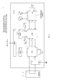
Сущность полезной модели поясняется также электрическими функциональными схемами устройства, блока управления и контроля, блока коммутации высоковольтного напряжения и блока соединителей, показанным соответственно на фиг. 1, 2, 3 и 4.The essence of the utility model is also illustrated by the electrical functional diagrams of the device, the control and monitoring unit, the high-voltage voltage switching unit and the connector unit, shown respectively in FIG. 1, 2, 3 and 4.
На фиг. 1 приняты следующие обозначения:In FIG. 1 adopted the following notation:
1 - корпус,1 - housing
2 - крышка,2 - cover
3 - блок внешнего электропитания (БВЭП), 220В, 50 Гц, собственная разработка,3 - block external power supply (BEP), 220V, 50 Hz, own development,
4 - источник внутреннего электропитания (ИВЭП), Nes 15-5, фирма «Меаn Well»,4 - source of internal power supply (IWEP), Nes 15-5, the company "Man Well",
5 - источник высоковольтного испытательного напряжения (ИВИН), трансформатор RSTN 75, 1 - 400 - 23 - 02, фирма «Michael Rieder»,5 - source of high voltage test voltage (IVIN), transformer RSTN 75, 1 - 400 - 23 - 02, the company "Michael Rieder",
6 - блок управления и контроля (БУК), собственная разработка,6 - control and monitoring unit (BUK), own development,
7 - блок коммутации высоковольтного напряжения (БКВН), собственная разработка,7 - switching unit high voltage (BKVN), own development,
8 - блок соединителей (БС), собственная разработка,8 - connector block (BS), own development,
9, 10, 11 и 12 - первый, второй, третий и четвертый индикаторы напряжения (ИН), лампа неоновая с держателем, 220 В, N701R, фирма «ЧИП и ДИП»,9, 10, 11 and 12 - the first, second, third and fourth voltage indicators (IN), neon lamp with holder, 220 V, N701R, the company "CHIP and DIP",
13 - концевой выключатель (КВК), В614, фирма «ЧИП и ДИП».13 - limit switch (KVK), B614, the company "CHIP and DIP".
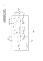
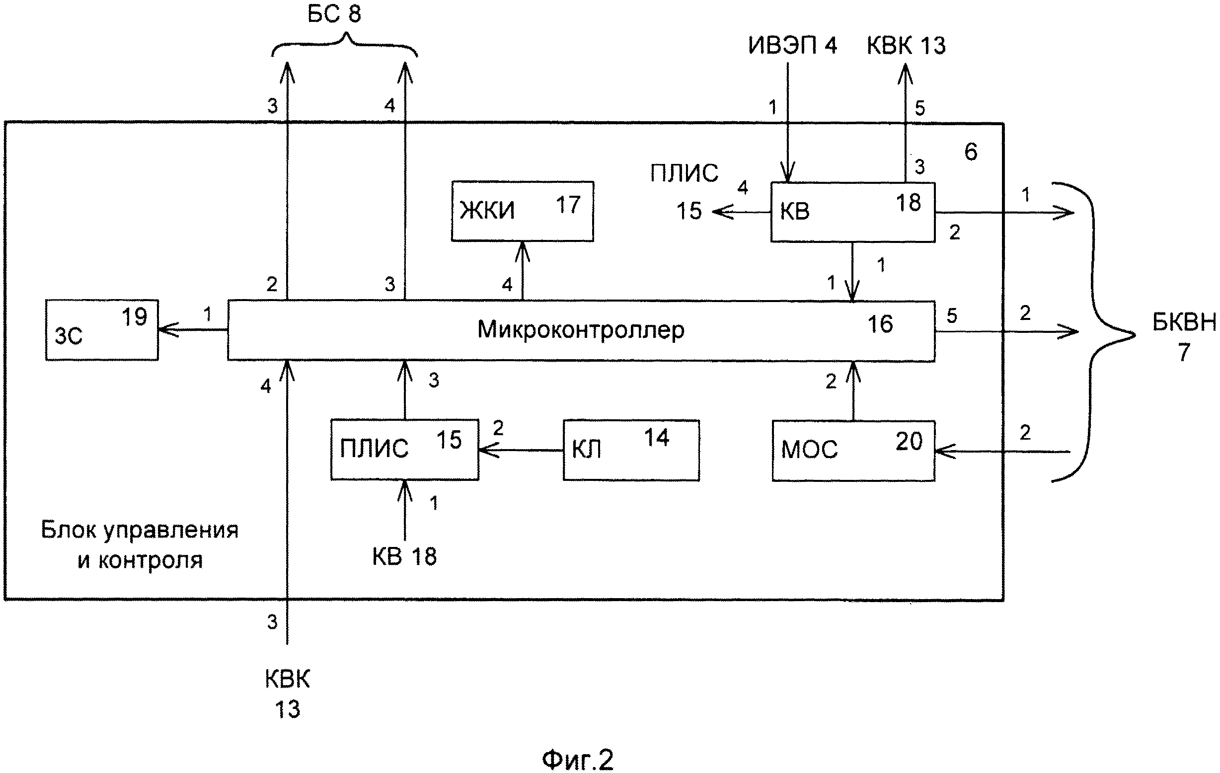
На фиг. 2 приняты следующие обозначения:In FIG. 2 adopted the following notation:
14 - клавиатура (КЛ), АК1604 - N - WWB Платан, ЗАО «Компонентс»,14 - keyboard (KL), AK1604 - N - WWB Platan, CJSC Components,
15 - программируемая логическая интегральная схема (ПЛИС), EPM712BSTC, фирма «Альтера»,15 - programmable logic integrated circuit (FPGA), EPM712BSTC, the company "Altera",
16 - микроконтроллер (МК), Atmega 128, фирма «Atmel»,16 - microcontroller (MK), Atmega 128, the company "Atmel",
17 - жидкокристаллический индикатор (ЖКИ), МТ - 16S2P -3YLG, фирма «МЭЛТ»,17 - liquid crystal indicator (LCD), MT - 16S2P-3YLG, the company "MELT",
18 - конвертор (KB), преобразователь DC/DC AM3N - 0505 SZ, компания «Компэл»,18 - converter (KB), DC / DC converter AM3N - 0505 SZ, Kompel company,
19 - звуковой сигнализатор (ЗС), НСМ1206Х, компания «Компэл»,19 - sound signaling device (ЗС), НСМ1206Х, Kompel company,
20 - модуль обработки сигнала (МОС), оптрон HCPL-0600, фирма «Промэлектроника».20 - signal processing module (MOS), optocoupler HCPL-0600, the company "Promelectronics".
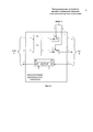
На фиг. 3 приняты следующие обозначения:In FIG. 3 adopted the following notation:
21 - реле (РЛ), G5V-1, фирма «Omron»,21 - relay (RL), G5V-1, the company "Omron",
22 и 23 - первый и второй коммутаторы (КМ), высоковольтные оптроны МОС 3063М, фирма «Fairchild»,22 and 23 - the first and second switches (KM), high-voltage optocouplers MOS 3063M, the company "Fairchild",
24 - датчик пробоя (ДП), собственная разработка,24 - breakdown sensor (DP), own development,
25 - высоковольтный оптрон (ВОП), КР 3010, фирма «Протон»,25 - high-voltage optocoupler (VOP), KR 3010, the company "Proton",
26 - токоограничивающий резистор (TOP), SQP10Bт, 11,2 кОм, фирма «ЧИП и ДИП».26 - current-limiting resistor (TOP), SQP10Bt, 11.2 kOhm, the company "CHIP and DIP".
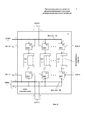
На фиг. 4 приняты следующие обозначенияIn FIG. 4 the following notation
27 - коммутирующие элементы (КЭ), ТВ - 2 (385), фирма «Автаком»,27 - switching elements (CE), TV - 2 (385), Avtakom company,
28 - высоковольтная шина (ВШ) «А», конструктивный элемент (проводник на плате печатного монтажа),28 - high voltage bus (VS) "A", structural element (conductor on the printed circuit board),
29 - ВШ «Б», конструктивный элемент (проводник на плате печатного монтажа),29 - VS “B”, structural element (conductor on a printed circuit board),
30 и 31 - первые и вторые коммутирующие высоковольтные оптроны (КВО), МОС 3063М, фирма «Fairchild».30 and 31 - the first and second switching high-voltage optocouplers (KVO), MOS 3063M, Fairchild.
Описание элементов заявляемого устройстваDescription of the elements of the claimed device
Блок внешнего электропитания (БВЭП) 3 предназначен для распределения сетевого напряжения 220 В, 50 Гц между ИВЭП 4 и ИВИН 5.The external power supply unit (BEP) 3 is designed to distribute the mains voltage of 220 V, 50 Hz between
Источник внутреннего электропитания (ИВЭП) 4 предназначен для формирования напряжения 5 В для питания МК 16 и ПЛИС 15 БУК 6, РЛ 21 БКВН 7, КВК 13 корпуса 1.The internal power supply (IVEP) 4 is designed to generate a voltage of 5 V for supplying
Источник высоковольтного испытательного напряжения (ИВИН) 5 предназначен для формирования высоковольтного напряжения амплитудой 500 В, частотой 50 Гц и подачи его на проверяемые изделия через РЛ 21, первый и второй КМ 22 и 23 БКВН 7 и через ВШ «А» 28 и ВШ «Б» 29, первые и вторые КВО 30 и 31 и КЭ 27 БС 8, а также подачи сигналов на первые и вторые ИН 9 и 10.The source of high-voltage test voltage (IVIN) 5 is designed to generate a high-voltage voltage with an amplitude of 500 V, a frequency of 50 Hz and supply it to the products under test through
Блок управления и контроля (БУК) 6 предназначен для формирования сигналов управления БКВН 7 и БС 8 посредством КЛ 14, ПЛИС 15, МК 16 и ЖКИ 17, а также для контроля процесса испытаний посредством обратной связи МК 16 с БС 8, ДП 24 БКВН 7, МОС 20 и визуализации на ЖКИ 17.The control and monitoring unit (BUK) 6 is designed to generate control signals BKVN 7 and
Блок коммутации высоковольтного напряжения (БКВН) 7 предназначен для обеспечения коммутации испытательного напряжения на БС 8 и соответственно на проверяемые изделия посредством РЛ 21, первого и второго КМ 22 и 23, а также для обеспечения обратной связи МК 16 БУК 6 с БС 8 посредством ДП 24.The high-voltage voltage switching unit (BKVN) 7 is designed to provide switching of the test voltage to
Блок соединителей (БС) 8 предназначен для подключения проверяемых изделий посредством КЭ 27 и обеспечения подачи и коммутации испытательного напряжения на проверяемые изделия посредством ВШ «А» 28 и ВШ «Б» 29 и первых и вторых КВО 30 и 31, а также для обеспечения обратной связи с МК 16 БУК 6 и подачи сигналов на третьи и четвертые ИН 11 и 12.The connector block (BS) 8 is designed to connect the tested products by KE 27 and ensure the supply and switching of the test voltage to the tested products by VSH "A" 28 and VSH "B" 29 and the first and
Первый и второй индикаторы напряжения (ИН) 9 и 10 предназначены для визуализации наличия высоковольтного напряжения на выходах ИВИН 5.The first and second voltage indicators (IN) 9 and 10 are designed to visualize the presence of high-voltage voltage at the outputs of
Третий и четвертый индикаторы напряжения (ИН) 11 и 12 предназначены для визуализации наличия высоковольтного напряжения на входах КЭ 27 БС 8.The third and fourth voltage indicators (IN) 11 and 12 are designed to visualize the presence of high-voltage voltage at the inputs of
Концевой выключатель (КВК) 13 предназначен для размыкания цепи и снятия высоковольтного напряжения с КЭ 27 БС 8 при подъеме крышки 2 корпуса 1.Limit switch (KVK) 13 is designed to open the circuit and remove high voltage from
Клавиатура (КЛ) 14 БУК 6 предназначена для введения исходных данных контроля проверяемых изделий в МК 16 через ПЛИС 15 с отображением информации на ЖКИ 17.Keyboard (CL) 14
Программируемая логическая интегральная схема (ПЛИС) 15 БУК 6 предназначена для программирования и введения параметров контроля проверяемых изделий в МК 16 посредством КЛ 14.Programmable logic integrated circuit (FPGA) 15
Микроконтроллер (МК) 16 БУК 6 предназначен для производства процесса испытаний в заданном оператором режиме, а также для управления, связи и контроля ЗС 19, БС 8, ЖКИ 17, БКВН 7 и МОС 20.The microcontroller (MK) 16
Жидкокристаллический индикатор (ЖКИ) 17 БУК 6 предназначен для получения и визуализации информации от МК 16.The liquid crystal indicator (LCD) 17
Конвертор (KB) 18 БУК 6 предназначен для получения напряжения 5 В от ИВЭП 4, преобразования напряжения 5 В в 5 Ви (изолированное) и распределения питания между МК 16, БКВН 7, КВК 13 и ПЛИС 14, а также для образования совместно с МОС 20 БУК 6 и РЛ 21 первой ступени гальванической развязки КЛ 14 и ЖКИ 17 БУК 6 от электрических цепей ИВЭП 4 и ИВИН 5.Converter (KB) 18
Звуковой сигнализатор (ЗС) 19 БУК 6 предназначен для оповещения об окончания контроля в случае соответствия изоляции техническим условиям или фиксации пробоя изоляции (нарушения электрической прочности) испытываемого изделия по сигналу от МК 16.The sound signaling device (ЗС) 19
Модуль обработки сигнала (МОС) 20 БУК 6 предназначен для выпрямления и усиления сигнала окончания контроля в случае соответствия изоляции техническим условиям или фиксации пробоя изоляции от ДП 24 БКВН 7 и передачи этого сигнала в МК 16, а также для образования совместно с KB 18, РЛ 21 БКВН 7 первой ступени гальванической развязки КЛ 14 и ЖКИ 17 БУК 6 от электрических цепей ИВЭП 4 и ИВИН 5.The signal processing module (MOS) 20
Реле (РЛ) 21 БКВН 7 предназначено для подачи напряжения питания 5 В от KB 18 БУК 6 и сигналов управления от МК 16 БУК 6 первому и второму КМ 21 и 22, а также для образования совместно с KB 18, МОС 20 БУК 6 первой ступени гальванической развязки КЛ 14 и ЖКИ 17 БУК 6 от электрических цепей ИВЭП 4 и ИВИН 5.The relay (RL) 21
Первый и второй коммутаторы (КМ) 22 и 23 БКВН 7 предназначены для приема испытательного напряжения от ИВИН 5 и подачи его на проверяемые изделия посредством ВШ «А» 28 и ВШ «Б» 29, первых и вторых КВО 30 и 31 и КЭ 27 БС 8, а также для образования совместно с ДП 24 второй ступени гальванической развязки КЛ 14 и ЖКИ 17 БУК 6 от электрических цепей ИВЭП 4 и ИВИН 5. Кроме того, применение в качестве первого и второго КМ 22 и 23 высоковольтных оптронов со встроенными детекторами определения и управления прохождением переменного коммутируемого высоковольтного напряжения через «0» позволяет исключить подачу высоковольтного напряжения на испытываемые изделия в моменты близкие к амплитудным значениям, что обеспечивает плавное повышение испытательного высоковольтного напряжения в пределах 5 миллисекунд при частоте 50 Гц и соответственно предохранение от пробоя (повреждения) изоляции испытываемого изделия при возможных «скачках» испытательного высоковольтного напряжения.The first and second switches (KM) 22 and 23 of the
Датчик пробоя (ДП) 24 БКВН 7 и высоковольтный оптрон (ВОП) 25 в его составе предназначены для получения сигнала окончания контроля в случае соответствия изоляции техническим условиям или фиксации пробоя изоляции (нарушения электрической прочности) испытываемого изделия от БС 8 в случае пробоя изоляции проверяемого изделия и передачи этого сигнала в МОС 20 и МК 16 БУК 6, а также для образования совместно с первым и вторым КМ 22 и 23 второй ступени гальванической развязки КЛ 14 и ЖКИ 17 БУК 6 от электрических цепей ИВЭП 4 и ИВИН 5.Breakdown sensor (DP) 24 BKVN 7 and a high-voltage optocoupler (VOP) 25 in its composition are designed to receive a signal of termination of control in case of insulation compliance with technical conditions or fixation of insulation breakdown (violation of electrical strength) of the tested product from
Токоограничивающий резистор (ТОР) 26 в составе ДП 24 БКВН 7 предназначен его для защиты от выхода из строя при включении в цепь высоковольтного напряжения.The current-limiting resistor (TOR) 26 as part of the
Коммутирующие элементы (КЭ) 27 БС 6 предназначены для подключения испытываемых изделий, подачи и коммутации на полюса этих изделий высоковольтного испытательного напряжения от ИВИН 5 через первый и второй КМ 22 и 23 БКВН 7 и ВШ «А» и «Б» 28 и 29.The switching elements (CE) 27
Первые и вторые коммутирующие высоковольтные оптроны (КВО) 30 и 31 БС 6 предназначены для подключения КЭ 27 к ВШ «А» и «Б» 28 и 29 БС 6 и соответственно полюсов испытываемых изделий к необходимому полюсу ИВИП 5 по сигналам управления от МК 16 БУК 6.The first and second switching high-voltage optocouplers (KVO) 30 and 31
Описание работы программируемого устройства автоматизированного контроля электрической прочности изоляцииDescription of the work of a programmable device for automated control of dielectric strength
Все составные части заявляемого устройства установлены в металлическом корпусе 1 с крышкой 2 и заземляющей шиной (на схеме не обозначена) и находятся в конструктивном единстве и функциональной взаимосвязи, внутренний электромонтаж осуществляется через разъемы∗∗ (∗∗)- на схемах не показаны, здесь и далее) составных частей, а также монтажными жгутами∗∗ и перемычками∗∗, т.е. технический результат обеспечивается совокупностью признаков всех элементов конструкции, при этом исключение одного из элементов конструкции исключает и возможность качественного функционирования в соответствии с решаемыми задачами.All components of the claimed device are installed in a
Собирают схему устройства.Assemble a device diagram.
Сеть промышленного напряжения 220 В, 50 Гц подключают к входу БВЭП 3, первый выход БВЭП 3 соединяют с входом ИВЭП 4, а второй выход БВЭП 3 - с входом ИВИН 5, выход ИВЭП 4 через первый вход БУК 6 соединяют с входом KB 18, первый выход которого соединяют с первым входом МК 16, второй выход KB 18 соединяют через первый выход БУК 6 с первым входом БКВН 7, а четвертый выход KB 18 - с первым входом ПЛИС 15, второй вход которой соединяют с выходом КЛ 14, а выход ПЛИС 15 соединяют с третьим входом МК 16, четвертый выход МК 16 соединяют с входом ЖКИ 17, а пятый выход МК 16 через второй выход БУК 6 - со вторым входом БКВН 7, первый и второй входы БКВН 7 соединяют соответственно с первым и вторым входами РЛ 21, первый и второй выходы РЛ 21 - с первыми входами первого и второго КМ 22 и 23, вторые входы которых соединяют соответственно через четвертый и пятый входы БКВН 7 с первым и вторым выходами ИВИН 5, а выходы первого и второго КМ 22 и 23 соответственно через первый и второй выходы БКВН 7 соединяют с первым и вторым входами БС 6 и соответственно через ВШ «А» и «Б» 28 и 29 с первыми входами первых и вторых КВО 30 и 31 и первыми и вторыми входами каждого КЭ 27 16, второй и третий выходы МК 16 соединяют соответственно через третий и четвертый выходы БУК 6 с третьими и четвертыми входами БС 8 и соответственно со вторыми входами первых и вторых КВО 30 и 31 и первыми и вторыми входами каждого КЭ 27, кроме того, первые входы вторых КВО 31 соединяют между собой и через первый выход БС 8 с третьим входом БКВН 7 и соответственно с входом ТОР 26, являющимся входом ДП 24, выход ТОР 26 соединяют с входом ВОП 25, выход которого, являющийся выходом ДП 24 через третий выход БКВН 7 соединяют со вторым входом БУК 6 и соответственно с входом МОС 20, выход которого соединяют со вторым входом МК 16, вход КВК 13 соединяют через крышку 2, корпус 1 и пятый выход БУК 6 с третьим выходом KB 18, первый выход КВК 13 через третий вход БУК 6 соединяют с четвертым входом МК 16, а второй выход КВК 13 - с заземляющей шиной корпуса 1, вход ЗС 19 соединяют с первым выходом МК 16, входы первого и второго ИН 9 и 10 соединяют соответственно с первым и вторым выходами ИВИН 5, а входы третьего и четвертого ИН 11 и 12 соединяют соответственно через второй и третий выходы БС 8 и ВШ «А» и «Б» 28 и 29 с КЭ 27. При этом KB 18, РЛ 21 и МОС 20 образуют первую ступень гальванической развязки (ГР) КЛ 14 и ЖКИ 17 от электрических цепей БВЭП 3 и ИВИН 5, а первый и второй КМ 22 и 23 и ДП 24 - вторую ступень ГР, указанные элементы KB 18, РЛ 21, МОС 20, КМ 22 и 23 и ДП 24 обладают функцией гальванической изоляции и надежно за счет двух ступеней разделяют высоковольтное и низкое напряжения для обеспечения защиты персонала в случае пробоя изоляции путем исключения попадания высоковольтного напряжения на элементы управления и контроля КЛ 14 и ЖКИ 17.An industrial voltage network of 220 V, 50 Hz is connected to the input of the BVEP 3, the first output of the BVEP 3 is connected to the input of IVEP 4, and the second output of BVEP 3 is connected to the input of IVIN 5, the output of IVEP 4 through the first input of BUK 6 is connected to input KB 18, the first the output of which is connected to the first input of MK 16, the second output of KB 18 is connected through the first output of the BUK 6 to the first input of the BKVN 7, and the fourth output of KB 18 is connected to the first input of the FPGA 15, the second input of which is connected to the output of the CL 14, and the output of the FPGA 15 connected to the third input of MK 16, the fourth output of MK 16 is connected to the input of the LCD 17, and the fifth output of MK 16 through the second the output of the BUK 6 is with the second input of the BKVN 7, the first and second inputs of the BKVN 7 are connected respectively to the first and second inputs of the RL 21, the first and second outputs of the RL 21 are connected to the first inputs of the first and second KM 22 and 23, the second inputs of which are connected respectively the fourth and fifth inputs of BKVN 7 with the first and second outputs of IVIN 5, and the outputs of the first and second KM 22 and 23, respectively, through the first and second outputs of BKVN 7 are connected to the first and second inputs of BS 6 and, respectively, through the VS “A” and “B” 28 and 29 with the first inputs of the first and second KVO 30 and 31 and the first and second inputs each KE 27 16, the second and third outputs of MK 16 are connected respectively through the third and fourth outputs of the BUK 6 with the third and fourth inputs of BS 8 and, respectively, with the second inputs of the first and second KVO 30 and 31 and the first and second inputs of each KE 27, in addition , the first inputs of the second KVO 31 are connected to each other and through the first output of the BS 8 with the third input of the BKVN 7 and, respectively, with the input of the TOP 26, which is the input of the DP 24, the output of the TOP 26 is connected to the input of the VOP 25, the output of which is the output of the DP 24 through the third the output of the BKVN 7 is connected to the second input of the BUK 6 and, accordingly, Naturally, with the input of MOS 20, the output of which is connected to the second input of MK 16, the input of KVK 13 is connected through cover 2, the housing 1, and the fifth output of BUK 6 with the third output of KB 18, the first output of KVK 13 through the third input of BUK 6 is connected to the fourth input of MK 16, and the second output of the CVC 13 - with the grounding bus of the housing 1, the input of the AP 19 is connected to the first output of the MK 16, the inputs of the first and second ID 9 and 10 are connected respectively to the first and second outputs of IVIN 5, and the inputs of the third and fourth ID 11 and 12 connect respectively through the second and third outputs BS 8 and VS “A” and “B” 28 and 29 with KE 27. In this
Контролируемое (испытываемое) изделие, например многожильный электрический кабель, (на схемах не обозначено) подключают к соответствующим входам КЭ 27 БС 8 при отсутствии высоковольтного напряжения на КЭ 27 БС 8 (при поднятой крышке 2 и разомкнутом КВК 13).A controlled (tested) product, for example, a multicore electric cable (not shown in the diagrams), is connected to the corresponding inputs of
БВЭП 3 и ИВЭП 4 обеспечивают электропитание +5 В соответствующих составных частей устройства, а ИВИН 5 - необходимое испытательное напряжение 500 В (по амплитуде), KB 18 формирует напряжение +5 Ви (изолированное), КВК 13 при подъеме крышки 2 корпуса 1 размыкает цепь и снимает высоковольтное напряжением с КЭ 27 БС8, первый, второй, третий и четвертый ИН 9, 10, 11 и 12 сигнализируют о наличии высоковольтного напряжения на выходах ИВИН 5 и на входах КЭ 27 БС 8, а встроенные детекторы∗∗ определения и управления прохождением переменного коммутируемого высоковольтного напряжения через «0» первого и второго КМ 22 и 23 исключают подачу высоковольтного напряжения на испытываемые изделия в моменты близкие к амплитудным значениям, а также обеспечивают плавное повышение испытательного высоковольтного напряжения в пределах 5 миллисекунд при частоте 50 Гц и соответственно предохранение от пробоя (повреждения) изоляции испытываемого изделия при возможных «скачках» испытательного высоковольтного напряжения.
Посредством КЛ 14, ПЛИС 15 и МК 16 устанавливают (программируют) режимы предварительной экспресс проверки (кратковременной подачи высоковольтного напряжения на каждую цепь испытываемого изделия, с целью предварительного определения короткого замыкания между жилами) или полной проверки, при этом на ЖКИ отображается введенная информация.By means of
Посредством МК 16 при закрытой крышке 2 корпуса 1 формируют управляющие сигналы для ЗС 19, первых и вторых КВО 30 и 31, ЖКИ 17, РЛ 21 и соответственно для первого и второго КМ 22 и 23 БКВН 7, а также принимают информационные сигналы от МОС 20, КЛ 14 через ПЛИС 15 и от КВК 13.Using
Посредством МК 16 управляют первыми и вторыми КВО 30 и 31 и подключают необходимые полюсы испытываемого изделия к тому или иному полюсу ИВИН 5 через КМ 22 и 23 и ВШ «А» и «Б» 28 и 29.By means of
Посредством МК 16 и РЛ 21 управляют первым и вторым КМ 22 и 23, которые через ВШ 28 и 29 подают испытательное напряжение на входы КЭ 27 и соответственно на испытываемые изделия при выбранном режиме проверки.By means of
Производят предварительную экспресс проверку, для максимально возможной гарантии от пробоя изоляции при полной проверке, занимающей значительно большее время по сравнению с предварительной, поскольку при полной проверке короткое замыкание может быть обнаружено в одной из последних жил электрического кабеля, что, после устранения дефекта, приведет к необходимости повторной проверки предыдущих жил, и соответственно к затратам дополнительного времени, при этом первыми и вторыми КВО 30 и 31 полюсы «А» (условно) жил испытываемого изделия поочередно подключают к полюсу «А» (условно) ИВИН 5, а полюс «Б» (условно) одной из жил изделия подключают к полюсу «Б» (условно) ИВИН 5, затем кратковременно с выдержкой в течение 1 секунды подают высоковольтное испытательное напряжение 500 В, в зависимости от требований технических условий (ТУ) на конкретное изделие, и фиксируют отсутствие или наличие короткого замыкания, т.е. пробоя изоляции между упомянутыми жилами и изоляцией отдельно подключенной жилы и т.д. по каждой жиле изделия.A preliminary express test is performed to ensure the maximum possible guarantee against breakdown of insulation during a full test, which takes much longer than a preliminary test, because during a full test a short circuit can be detected in one of the last conductors of the electric cable, which, after eliminating the defect, will lead to the need to re-check the previous cores, and accordingly to the cost of additional time, while the first and
После предварительной экспресс проверки производят полную или основную проверку, при этом полюсы «А» (условно) жил испытываемого изделия подключают к полюсу «А» (условно) ИВИН 5, а полюсы «Б» (условно) - к полюсу «Б» (условно) ИВИН 5, затем поочередно, на каждую жилу подают высоковольтное испытательное напряжение 500 В с выдержкой в течение 1 минуты, в зависимости от ТУ на конкретное изделие.After preliminary express checks, a full or basic check is performed, while the poles “A” (conditionally) of the test product conductors are connected to the pole “A” (conditionally)
После завершения проверки (контроля) в случае соответствия изоляции техническим условиям или фиксации пробоя изоляции испытываемого изделия информационные сигналы от вторых КВО 31 БС 8 поступают в ТОР 26 и ВОП 25 ДП 24 БКВН 7 и далее в МСО 20 для выпрямления и усиления, а затем в МК 16 и ЗС 19 для звуковой сигнализации и в ЖКИ 17 для отображения полученной информации.After completion of the check (control) in the case of insulation compliance with technical specifications or fixing a breakdown of the insulation of the tested product, information signals from the
Технический результат от использования полезной модели заключается:The technical result of using the utility model is:
- в повышении безопасности работы оператора введением двух ступеней гальванической развязки элементов управления и силовых цепей, звукового сигнала об окончании проверки в случае соответствия изоляции техническим условиям или фиксации пробоя изоляции испытываемых изделий, индикаторов напряжения о формировании высоковольтного напряжения на выходе источника высоковольтного испытательного напряжения и появления высоковольтного напряжения на коммутирующих элементах блока соединителей, повышением защищенности датчика пробоя, а также предохранением от пробоя (повреждения) изоляции при возможных «скачках» испытательного высоковольтного напряжения;- to increase the safety of the operator by introducing two stages of galvanic isolation of the control elements and power circuits, an audible signal to complete the test in case of insulation compliance with technical conditions or fixing a breakdown of insulation of the tested products, voltage indicators on the formation of a high voltage voltage at the output of the source of high voltage test voltage and the appearance of high voltage voltage on the switching elements of the connector block, increasing the security of the breakdown sensor, as well as e protection against breakdown (damage) of insulation during possible “surges” in the test high-voltage voltage;
- в повышение удобства работы введением предварительной экспресс проверки кратковременной подачей испытательного высоковольтного напряжения на каждую цепь испытываемого изделия и автоматического подключения КЭ БС и соответственно полюсов испытываемых изделий к необходимому полюсу источника ИВИН.- to increase the convenience of work by introducing a preliminary express check by short-term supply of a test high-voltage voltage to each circuit of the tested product and automatic connection of the CE BS and, accordingly, the poles of the tested products to the required pole of the IVIN source.
Указанный технический результат достигается совокупностью отличительных признаков, а именно снабжением блока управления и контроля (БУК) программируемой логической интегральной схемой (ПЛИС), конвертором (KB) и модулем обработки сигнала (МОС), в снабжении блока коммутации высоковольтного напряжения (БКВН) первым и вторым коммутаторами (КМ), выполнением датчика пробоя (ДП) в виде высоковольтного оптрона (ВОП) и токоограничивающего резистора (ТОР), снабжением блока соединителей (БС) двумя высоковольтными шинами (ВШ) «А» и «Б», а каждого коммутирующего элемента (КЭ) - первым и вторым коммутирующими высоковольтными оптронами (КВО), снабжением корпуса устройства концевым выключателем (КВК) для снятия высоковольтного напряжения с КЭ БС, введением звукового сигнализатора (ЗС) окончания контроля электрической прочности изоляции испытываемого изделия, а также введением первого, второго, третьего и четвертого индикаторов напряжений (ИН) наличия высоковольтного напряжения на выходах источника высоковольтного испытательного напряжения ИВИН и на входах КЭ БС.The specified technical result is achieved by a set of distinctive features, namely, by supplying a control and monitoring unit (BUC) with a programmable logic integrated circuit (FPGA), a converter (KB) and a signal processing module (MOS), in supplying the first and second high-voltage voltage switching unit (BKVN) switches (KM), the implementation of the breakdown sensor (DP) in the form of a high-voltage optocoupler (VOP) and a current-limiting resistor (TOP), supplying the block of connectors (BS) with two high-voltage buses (VS) "A" and "B", and each switch a switching element (CE) - the first and second switching high-voltage optocouplers (KVO), supplying the device body with an end switch (KVK) for removing high-voltage voltage from the BS KE, introducing an audible signaling device (ZS) of the end of the electrical insulation test of the tested product, as well as introducing the first , the second, third and fourth voltage indicators (IN) of the presence of high voltage at the outputs of the source of high voltage test voltage IVIN and at the inputs of the CE BS.
Представленные описание и схемы заявляемого устройства позволяют, применяя существующие материалы и унифицированные покупные комплектующие изделия, изготовить его промышленным способом и использовать для автоматизированного контроля электрической прочности изоляции различных электрических или электронных цепей электротехнических или радиоэлектронных изделий.The presented description and schemes of the claimed device allow, using existing materials and unified purchased component parts, to manufacture it industrially and use it for automated control of dielectric strength of insulation of various electrical or electronic circuits of electrical or electronic products.
Перечень обозначений на фиг. 1The notation in FIG. one
1 - корпус,1 - housing
2 - крышка,2 - cover
3 - блок внешнего электропитания (БВЭП),3 - block external power supply (BEP),
4 - источник внутреннего электропитания (ИВЭП),4 - source of internal power supply (IVEP),
5 - источник высоковольтного испытательного напряжения (ИВИН),5 - source of high voltage test voltage (IVIN),
6 - блок управления и контроля (БУК),6 - control unit and control (BUK),
7 - блок коммутации высоковольтного напряжения (БКВН),7 - switching unit high voltage (BKVN),
8 - блок соединителей (БС),8 - connector block (BS),
9, 10, 11 и 12 - первый, второй, третий и четвертый индикаторы напряжения (ИН),9, 10, 11 and 12 - the first, second, third and fourth voltage indicators (IN),
13 - концевой выключатель (КВК).13 - limit switch (KVK).
Перечень обозначений на фиг. 2The notation in FIG. 2
14 - клавиатура (КЛ),14 - keyboard (KL),
15 - программируемая логическая интегральная схема (ПЛИС),15 - programmable logic integrated circuit (FPGA),
16 - микроконтроллер (МК),16 - microcontroller (MK),
17 - жидкокристаллический индикатор (ЖКИ),17 - liquid crystal indicator (LCD),
18 - конвертор (KB),18 - converter (KB),
19 - звуковой сигнализатор (ЗС),19 - sound signaling device (ZS),
20 - модуль обработки сигнала (МОС).20 - signal processing module (MOS).
Перечень обозначений на фиг. 3The notation in FIG. 3
21 - реле (РЛ),21 - relay (RL),
22 и 23 - первый и второй коммутаторы (КМ),22 and 23 - the first and second switches (KM),
24 - датчик пробоя (ДП),24 - breakdown sensor (DP),
25 - высоковольтный оптрон (ВОП),25 - high voltage optocoupler (VOP),
26 - токоограничивающий резистор (ТОР).26 - current limiting resistor (TOP).
Перечень обозначений на фиг. 4The notation in FIG. four
27 - коммутирующие элементы (КЭ),27 - switching elements (CE),
28 - высоковольтная шина (ВШ) «А»,28 - high voltage bus (VS) "A",
29 - ВШ «Б»,29 - VS "B",
30 и 31 - первые и вторые коммутирующие высоковольтные оптроны (КВО).30 and 31 - the first and second switching high-voltage optocouplers (KVO).
Claims (3)
Priority Applications (1)
| Application Number | Priority Date | Filing Date | Title |
|---|---|---|---|
| RU2016126637/28U RU166345U1 (en) | 2016-07-01 | 2016-07-01 | PROGRAMMABLE DEVICE FOR AUTOMATED INSULATION ELECTRICAL CONTROL |
Applications Claiming Priority (1)
| Application Number | Priority Date | Filing Date | Title |
|---|---|---|---|
| RU2016126637/28U RU166345U1 (en) | 2016-07-01 | 2016-07-01 | PROGRAMMABLE DEVICE FOR AUTOMATED INSULATION ELECTRICAL CONTROL |
Publications (1)
| Publication Number | Publication Date |
|---|---|
| RU166345U1 true RU166345U1 (en) | 2016-11-20 |
Family
ID=57792778
Family Applications (1)
| Application Number | Title | Priority Date | Filing Date |
|---|---|---|---|
| RU2016126637/28U RU166345U1 (en) | 2016-07-01 | 2016-07-01 | PROGRAMMABLE DEVICE FOR AUTOMATED INSULATION ELECTRICAL CONTROL |
Country Status (1)
| Country | Link |
|---|---|
| RU (1) | RU166345U1 (en) |
Cited By (1)
| Publication number | Priority date | Publication date | Assignee | Title |
|---|---|---|---|---|
| RU2776635C1 (en) * | 2022-03-21 | 2022-07-22 | Общество с ограниченной ответственностью Научно-производственное предприятие "ЭКРА" | Kit of automated tests of electrical equipment with increased voltage |
-
2016
- 2016-07-01 RU RU2016126637/28U patent/RU166345U1/en not_active IP Right Cessation
Cited By (1)
| Publication number | Priority date | Publication date | Assignee | Title |
|---|---|---|---|---|
| RU2776635C1 (en) * | 2022-03-21 | 2022-07-22 | Общество с ограниченной ответственностью Научно-производственное предприятие "ЭКРА" | Kit of automated tests of electrical equipment with increased voltage |
Similar Documents
| Publication | Publication Date | Title |
|---|---|---|
| KR101016378B1 (en) | Switchgear for easy measurement of leakage current of ground wire | |
| JPH066916A (en) | Method and device for judging wiring connection | |
| RU166345U1 (en) | PROGRAMMABLE DEVICE FOR AUTOMATED INSULATION ELECTRICAL CONTROL | |
| RU166053U1 (en) | DEVICE OF AUTOMATED CONTROL OF ELECTRICAL STRENGTH OF INSULATION | |
| CN113608013A (en) | Non-contact electricity utilization detection device and detection method thereof | |
| RU2365013C1 (en) | Method of automatic repeated switching-on of power transmission line (ptl) | |
| EP2778693B1 (en) | Apparatus to verify an electrically safe work condition | |
| CN207976549U (en) | A kind of suspension type power-supply controller of electric for high-voltage switch gear detection device | |
| JP5883363B2 (en) | Power supply for lighting and polarity test | |
| CN204008911U (en) | A kind of coil apparatus proving installation | |
| CN104181413A (en) | Multifunctional relay protection experiment device and use method thereof | |
| KR100971996B1 (en) | Harness connecting apparatus for stardinizing power control of distributing board | |
| CN204649952U (en) | Based on the bushing shell for transformer monitoring device detection platform of synchro measure | |
| CN209471149U (en) | A kind of auxiliary connection device of high-voltage inverter test macro | |
| JP2017211219A (en) | Device for confirming secondary wiring connection state of current transformer for meters | |
| CN202886458U (en) | Real-time detection and alarm device for bypass flexible cable running current | |
| CN102982636B (en) | Small animal detection and alarm method for power transformation and distribution facility | |
| US20230208968A1 (en) | Telephone Line Testing Apparatus With Remote Control | |
| RU178299U1 (en) | Device for continuous monitoring of insulation resistance of a submersible electric cable and continuous monitoring of the resistance of windings of a submersible electric motor of an electric submersible pump installation | |
| CN204925295U (en) | Control point survey circuit and equipment ground measurement system | |
| CN209963629U (en) | Metal enclosed outlet cabinet for electric power system | |
| CN205015427U (en) | Neutral point multipoint earthing detection device based on high accuracy testing electric current | |
| CN204695499U (en) | A kind of high-potting district is anti-is strayed into device | |
| CN104423284A (en) | High-voltage electrification displaying and locking device | |
| CN106501558A (en) | A kind of safe mode of connection during electric power transmission line parameter testing |
Legal Events
| Date | Code | Title | Description |
|---|---|---|---|
| MM9K | Utility model has become invalid (non-payment of fees) |
Effective date: 20170702 |