RU166314U1 - SPRAY GUN WITH ROTATING NOZZLE - Google Patents
SPRAY GUN WITH ROTATING NOZZLE Download PDFInfo
- Publication number
- RU166314U1 RU166314U1 RU2015147550/05U RU2015147550U RU166314U1 RU 166314 U1 RU166314 U1 RU 166314U1 RU 2015147550/05 U RU2015147550/05 U RU 2015147550/05U RU 2015147550 U RU2015147550 U RU 2015147550U RU 166314 U1 RU166314 U1 RU 166314U1
- Authority
- RU
- Russia
- Prior art keywords
- specified
- tube
- gas
- gas supply
- rotating nozzle
- Prior art date
Links
Images
Classifications
-
- B—PERFORMING OPERATIONS; TRANSPORTING
- B05—SPRAYING OR ATOMISING IN GENERAL; APPLYING FLUENT MATERIALS TO SURFACES, IN GENERAL
- B05B—SPRAYING APPARATUS; ATOMISING APPARATUS; NOZZLES
- B05B3/00—Spraying or sprinkling apparatus with moving outlet elements or moving deflecting elements
- B05B3/14—Spraying or sprinkling apparatus with moving outlet elements or moving deflecting elements with oscillating elements; with intermittent operation
- B05B3/16—Spraying or sprinkling apparatus with moving outlet elements or moving deflecting elements with oscillating elements; with intermittent operation driven or controlled by the liquid or other fluent material discharged, e.g. the liquid actuating a motor before passing to the outlet
-
- B—PERFORMING OPERATIONS; TRANSPORTING
- B05—SPRAYING OR ATOMISING IN GENERAL; APPLYING FLUENT MATERIALS TO SURFACES, IN GENERAL
- B05B—SPRAYING APPARATUS; ATOMISING APPARATUS; NOZZLES
- B05B3/00—Spraying or sprinkling apparatus with moving outlet elements or moving deflecting elements
- B05B3/02—Spraying or sprinkling apparatus with moving outlet elements or moving deflecting elements with rotating elements
- B05B3/04—Spraying or sprinkling apparatus with moving outlet elements or moving deflecting elements with rotating elements driven by the liquid or other fluent material discharged, e.g. the liquid actuating a motor before passing to the outlet
- B05B3/06—Spraying or sprinkling apparatus with moving outlet elements or moving deflecting elements with rotating elements driven by the liquid or other fluent material discharged, e.g. the liquid actuating a motor before passing to the outlet by jet reaction
-
- B—PERFORMING OPERATIONS; TRANSPORTING
- B05—SPRAYING OR ATOMISING IN GENERAL; APPLYING FLUENT MATERIALS TO SURFACES, IN GENERAL
- B05B—SPRAYING APPARATUS; ATOMISING APPARATUS; NOZZLES
- B05B1/00—Nozzles, spray heads or other outlets, with or without auxiliary devices such as valves, heating means
- B05B1/005—Nozzles or other outlets specially adapted for discharging one or more gases
-
- B—PERFORMING OPERATIONS; TRANSPORTING
- B05—SPRAYING OR ATOMISING IN GENERAL; APPLYING FLUENT MATERIALS TO SURFACES, IN GENERAL
- B05B—SPRAYING APPARATUS; ATOMISING APPARATUS; NOZZLES
- B05B3/00—Spraying or sprinkling apparatus with moving outlet elements or moving deflecting elements
- B05B3/02—Spraying or sprinkling apparatus with moving outlet elements or moving deflecting elements with rotating elements
- B05B3/04—Spraying or sprinkling apparatus with moving outlet elements or moving deflecting elements with rotating elements driven by the liquid or other fluent material discharged, e.g. the liquid actuating a motor before passing to the outlet
-
- B—PERFORMING OPERATIONS; TRANSPORTING
- B05—SPRAYING OR ATOMISING IN GENERAL; APPLYING FLUENT MATERIALS TO SURFACES, IN GENERAL
- B05B—SPRAYING APPARATUS; ATOMISING APPARATUS; NOZZLES
- B05B7/00—Spraying apparatus for discharge of liquids or other fluent materials from two or more sources, e.g. of liquid and air, of powder and gas
- B05B7/02—Spray pistols; Apparatus for discharge
- B05B7/06—Spray pistols; Apparatus for discharge with at least one outlet orifice surrounding another approximately in the same plane
- B05B7/062—Spray pistols; Apparatus for discharge with at least one outlet orifice surrounding another approximately in the same plane with only one liquid outlet and at least one gas outlet
- B05B7/063—Spray pistols; Apparatus for discharge with at least one outlet orifice surrounding another approximately in the same plane with only one liquid outlet and at least one gas outlet one fluid being sucked by the other
- B05B7/064—Spray pistols; Apparatus for discharge with at least one outlet orifice surrounding another approximately in the same plane with only one liquid outlet and at least one gas outlet one fluid being sucked by the other the liquid being sucked by the gas
-
- B—PERFORMING OPERATIONS; TRANSPORTING
- B05—SPRAYING OR ATOMISING IN GENERAL; APPLYING FLUENT MATERIALS TO SURFACES, IN GENERAL
- B05B—SPRAYING APPARATUS; ATOMISING APPARATUS; NOZZLES
- B05B7/00—Spraying apparatus for discharge of liquids or other fluent materials from two or more sources, e.g. of liquid and air, of powder and gas
- B05B7/24—Spraying apparatus for discharge of liquids or other fluent materials from two or more sources, e.g. of liquid and air, of powder and gas with means, e.g. a container, for supplying liquid or other fluent material to a discharge device
- B05B7/2402—Apparatus to be carried on or by a person, e.g. by hand; Apparatus comprising containers fixed to the discharge device
- B05B7/2405—Apparatus to be carried on or by a person, e.g. by hand; Apparatus comprising containers fixed to the discharge device using an atomising fluid as carrying fluid for feeding, e.g. by suction or pressure, a carried liquid from the container to the nozzle
- B05B7/2435—Apparatus to be carried on or by a person, e.g. by hand; Apparatus comprising containers fixed to the discharge device using an atomising fluid as carrying fluid for feeding, e.g. by suction or pressure, a carried liquid from the container to the nozzle the carried liquid and the main stream of atomising fluid being brought together by parallel conduits placed one inside the other
-
- B—PERFORMING OPERATIONS; TRANSPORTING
- B05—SPRAYING OR ATOMISING IN GENERAL; APPLYING FLUENT MATERIALS TO SURFACES, IN GENERAL
- B05B—SPRAYING APPARATUS; ATOMISING APPARATUS; NOZZLES
- B05B7/00—Spraying apparatus for discharge of liquids or other fluent materials from two or more sources, e.g. of liquid and air, of powder and gas
- B05B7/24—Spraying apparatus for discharge of liquids or other fluent materials from two or more sources, e.g. of liquid and air, of powder and gas with means, e.g. a container, for supplying liquid or other fluent material to a discharge device
- B05B7/26—Apparatus in which liquids or other fluent materials from different sources are brought together before entering the discharge device
- B05B7/28—Apparatus in which liquids or other fluent materials from different sources are brought together before entering the discharge device in which one liquid or other fluent material is fed or drawn through an orifice into a stream of a carrying fluid
- B05B7/30—Apparatus in which liquids or other fluent materials from different sources are brought together before entering the discharge device in which one liquid or other fluent material is fed or drawn through an orifice into a stream of a carrying fluid the first liquid or other fluent material being fed by gravity, or sucked into the carrying fluid
-
- B—PERFORMING OPERATIONS; TRANSPORTING
- B08—CLEANING
- B08B—CLEANING IN GENERAL; PREVENTION OF FOULING IN GENERAL
- B08B3/00—Cleaning by methods involving the use or presence of liquid or steam
- B08B3/02—Cleaning by the force of jets or sprays
- B08B3/026—Cleaning by making use of hand-held spray guns; Fluid preparations therefor
- B08B3/028—Spray guns
-
- B—PERFORMING OPERATIONS; TRANSPORTING
- B08—CLEANING
- B08B—CLEANING IN GENERAL; PREVENTION OF FOULING IN GENERAL
- B08B5/00—Cleaning by methods involving the use of air flow or gas flow
- B08B5/02—Cleaning by the force of jets, e.g. blowing-out cavities
-
- B—PERFORMING OPERATIONS; TRANSPORTING
- B60—VEHICLES IN GENERAL
- B60S—SERVICING, CLEANING, REPAIRING, SUPPORTING, LIFTING, OR MANOEUVRING OF VEHICLES, NOT OTHERWISE PROVIDED FOR
- B60S3/00—Vehicle cleaning apparatus not integral with vehicles
- B60S3/04—Vehicle cleaning apparatus not integral with vehicles for exteriors of land vehicles
- B60S3/044—Hand-held cleaning arrangements with liquid or gas distributing means
Landscapes
- Nozzles (AREA)
Abstract
1. Пистолет-распылитель с вращающейся форсункой, содержащий:рукоять, включающую воздухоприемную трубку, соединяемую с внешним источником воздуха высокого давления для поступления сжатого воздуха, седло клапана, газоподводящую трубку, соединенную с передним концом указанного седла клапана, спусковой крючок, предназначенный для открывания указанного седла клапана с целью пропуска потока указанного сжатого воздуха в указанную газоподводящую трубку, причем указанная газоподводящая трубка включает воздухоподающий канал, сообщающийся с указанным седлом клапана и указанной воздухоприемной трубкой, и стыковочно-соединительный участок, расположенный на ее наружном конце вокруг конца указанного воздухоподающего канала; ивращающийся формирователь струи, причем указанный формирователь струи состоит из газопроводящей трубки, присоединенной к указанному стыковочно-соединительному участку указанной газоподводящей трубки, причем указанная газопроводящая трубка включает соединительный участок, расположенный на ее конце, дальнем по отношению к указанной газоподводящей трубке, и газопроводящий канал, проходящий в осевом направлении через ее противоположные концы и сообщающийся с указанным воздухоподающим каналом, и соединительной муфты, подшипника и вращающейся форсунки, установленных на указанный соединительный участок газопроводящей трубки, причем указанная соединительная муфта установлена на указанный подшипник и может приводиться в движение указанной вращающейся форсункой для вращения относительно указанного подшипника, причем указанная вращающаяся форсунка установлена на указанную1. A spray gun with a rotating nozzle, comprising: a handle including an air intake pipe connected to an external high pressure air source for receiving compressed air, a valve seat, a gas supply pipe connected to the front end of said valve seat, a trigger designed to open said valve seats to pass a stream of said compressed air into said gas supply pipe, said gas supply pipe including an air supply channel in communication with seemed valve seat and said air intake pipe and connection-connecting portion positioned at its outer end around the end of said air supply duct; a rotatable jet former, wherein said jet former consists of a gas conduit attached to said docking and connecting portion of said gas supply tube, said gas conduit comprising a connecting portion located at an end thereof distal to said gas supply tube and a gas conduit passing in the axial direction through its opposite ends and communicating with the specified air supply channel, and the coupling, bearing and BP -rotating nozzles installed on said gas conducting tube connecting portion, said coupler is mounted on said bearing and can be driven by rotating said nozzle to rotate relative to said bearing, said nozzle is mounted rotating on said
Description
ПРЕДПОСЫЛКИ СОЗДАНИЯ ПОЛЕЗНОЙ МОДЕЛИBACKGROUND OF USING A USEFUL MODEL
1. Область применения1 area of use
Настоящая полезная модель касается конструкции пистолета-распылителя и, в частности, пистолета-распылителя с вращающейся форсункой, включающего рукоять, снабженную газоподводящей трубкой, приставную трубку, присоединенную к газоподводящей трубке, и вращающийся формирователь струи, присоединенный к газоподводящей трубке и удерживающий вращающуюся форсунку в выпускном отверстии приставной трубки, с возможностью ее вращения, для эжекции сжатого воздуха.The present utility model relates to the design of a spray gun and, in particular, to a spray gun with a rotating nozzle, including a handle provided with a gas supply pipe, an attachment pipe attached to the gas supply pipe, and a rotary jet former connected to the gas supply pipe and holding the rotating nozzle in the outlet openings of an attached tube, with the possibility of its rotation, for ejection of compressed air.
2. Описание аналогов и прототипа2. Description of analogues and prototype
По мере развития техники все аспекты качества нашей жизни непрерывно совершенствовались. Для целей транспортировки широко используются автомобили и мотоциклы в качестве личных транспортных средств. Количество автомобилей и мотоциклов постоянно растет. Для мойки автомобилей и мотоциклов применяется ряд автоматических моющих машин. В этих автоматических моющих машинах для чистки автомобилей обычно применяются вращающиеся щетки. Чистка автомобилей вращающимися щетками не может эффективно удалять пятна и грязь с кромок или выпуклых и вогнутых поверхностей кузова автомобиля. Некоторые пользователи моют автомобиль вручную чистой водой, а затем удаляют остаточные водяные пятна с кузова автомобиля сухой тряпкой. Однако чистка автомобиля таким способом требует много усилий и времени.With the development of technology, all aspects of the quality of our life are continuously improved. For transportation purposes, cars and motorcycles are widely used as personal vehicles. The number of cars and motorcycles is constantly growing. For washing cars and motorcycles, a number of automatic washing machines are used. In these automatic car washing machines, rotating brushes are usually used. Cleaning cars with rotating brushes cannot effectively remove stains and dirt from the edges or convex and concave surfaces of the car body. Some users wash the car manually with clean water, and then remove residual water stains from the car body with a dry rag. However, cleaning a car in this way requires a lot of effort and time.
При осуществлении генеральной чистки пользователи обычно воздействуют на поверхность обрабатываемого объекта струей воды и одновременно протирают поверхность объекта щеткой или тряпкой. При чистке автомобиля или здания необходимо воздействовать на очищаемую поверхность сильной струей воды, а затем протирать поверхность щеткой или тряпкой. Для создания сильной струи воды, подаваемой на очищаемую поверхность, обычно водяной шланг присоединяют к водопроводному крану и сдавливают конец водяного шланга пальцами, направляя эжектируемую из конца шланга воду на очищаемую поверхность. После промывки поверхности струей воды для чистки помытой поверхности пользуются щеткой или тряпкой. Этот способ чистки является трудоемким и требует много воды, а, следовательно, не отвечает требованиям экономии энергии и воды. С целью решения проблемы излишней траты водных ресурсов созданы некоторые проекты, сочетающие использование воздуха высокого давления с водяным пистолетом для усиления воздействия сильной струи воды и контроля времени водопотребления, чтобы избежать причин больших потерь воды. На фиг. 8 показан традиционный пистолет-распылитель с вращающейся форсункой, выбранный в качестве прототипа (патентная заявка США №2003/0029933 А1, кл. В05В 7/12, публ. 13.02.2003 г.). Пистолет-распылитель А с вращающейся форсункой включает рукоятку А1, Т-образную трубку А2, жидкостной бачок A3 и узел В распылительного сопла. Узел В распылительного сопла включает рупорообразный тубус В1, имеющий винтовое соединение В11, расположенное на одном его конце и сочлененное с воздухоподающим концом А4 Т-образной трубки А2, вращающуюся трубку С, имеющую соединительный элемент С1, расположенный на одном ее конце, и вращательно присоединенную к воздухоподоющему концу А4 Т-образной трубки А2 внутри винтового соединения ВП, противовесы С2, смонтированные вокруг периферии вращающейся трубки С, погружную трубку С3. пропущенную сквозь вращающуюся трубку С и Т-образную трубку А2 и опущенную в жидкостной бачок A3, и форсуночный распылитель С31, расположенный на конце погружной трубки С3. При применении, поток сжатого воздуха от внешнего источника сжатого воздуха направляется через воздушный канал в рукоятке А1 и Т-образную трубку А2 во вращающуюся трубку С.Когда сжатый воздух проходит через вращающуюся трубку С и форсуночный распылитель С31 погружной трубки С3, создается эффект Вентури - засасывание жидкости из жидкостного бачка A3 в Т-образную трубку А2 для смешивания со сжатым воздухом вокруг форсуночного распылителя С31, с тем чтобы воздушно-жидкостная смесь могла быть вытолкнута из рупорообразного тубуса В1 в виде аэрозоля мелких капелек для применения. Однако в действительной заявке, когда вращающаяся трубка С пистолета-распылителя А с вращающейся форсункой потоком сжатого воздуха приводится во вращение в рупорообразном тубусе В1, достигая высокой скорости, вращающаяся трубка С и противовесы С2 будут 3When carrying out general cleaning, users usually expose the surface of the object to be treated with a jet of water and at the same time wipe the surface of the object with a brush or rag. When cleaning a car or building, it is necessary to expose the surface to be cleaned with a strong jet of water, and then wipe the surface with a brush or a rag. To create a strong jet of water supplied to the surface to be cleaned, usually a water hose is attached to the water tap and squeeze the end of the water hose with your fingers, directing the water ejected from the end of the hose to the surface to be cleaned. After washing the surface with a jet of water, use a brush or rag to clean the washed surface. This method of cleaning is time-consuming and requires a lot of water, and therefore does not meet the requirements of saving energy and water. In order to solve the problem of excessive waste of water resources, several projects have been created combining the use of high pressure air with a water gun to enhance the effects of a strong jet of water and control the time of water consumption in order to avoid the causes of large water losses. In FIG. Figure 8 shows a traditional spray gun with a rotating nozzle, selected as a prototype (US patent application No. 2003/0029933 A1, CL B05B 7/12, publ. February 13, 2003). The spray gun A with a rotating nozzle includes a handle A1, a T-shaped tube A2, a fluid reservoir A3 and a nozzle assembly B. The spray nozzle assembly B includes a horn-shaped tube B1 having a screw connection B11 located at one end thereof and articulated to the air supply end A4 of the T-shaped tube A2, a rotating tube C having a connecting member C1 located at one end thereof and rotationally connected to the air-supplying end A4 of the T-shaped tube A2 inside the screw connection VP, counterweights C2 mounted around the periphery of the rotating tube C, the immersion tube C3. passed through the rotating tube C and the T-shaped tube A2 and lowered into the fluid reservoir A3, and the nozzle atomizer C31 located at the end of the immersion tube C3. When applied, the flow of compressed air from an external source of compressed air is directed through the air channel in the handle A1 and the T-shaped tube A2 into the rotating tube C. When the compressed air passes through the rotating tube C and the nozzle atomizer C31 of the immersion tube C3, the Venturi effect is created - suction liquid from the liquid tank A3 into the T-shaped tube A2 for mixing with compressed air around the nozzle atomizer C31, so that the air-liquid mixture can be pushed out of the horn-shaped tube B1 in the form of an aerosol I'm fine droplets for use. However, in the actual application, when the rotating tube C of the spray gun A with the rotating nozzle is driven by a stream of compressed air into the horn-shaped tube B1, reaching high speed, the rotating tube C and the counterweights C2 will be 3
тереться о внутреннюю стенку рупорообразного тубуса В1, вызывая повреждения рупорообразного тубуса В1 в процессе эксплуатации. После продолжительного использования соединительный участок между соединительным элементом С1 вращающейся трубки С и воздухоподающим концом А4 Т-образной трубки А2 может легко сломаться, и отломившийся компонент может быть выброшен из рупорообразного тубуса В1, приведя к несчастному случаю.rub against the inner wall of the horn-shaped tube B1, causing damage to the horn-shaped tube B1 during operation. After prolonged use, the connecting portion between the connecting element C1 of the rotating tube C and the air supply end A4 of the T-shaped tube A2 can easily break and the broken component can be ejected from the horn-shaped tube B1, resulting in an accident.
Поэтому желательно создать пистолет-распылитель с вращающейся форсункой, устраняющий проблему трения между вращающейся форсункой и внутренней стенкой рупорообразного тубуса, а также проблему возможности поломки вращающейся трубки в процессе работы.Therefore, it is desirable to create a spray gun with a rotating nozzle, eliminating the problem of friction between the rotating nozzle and the inner wall of the horn-shaped tube, as well as the problem of the possibility of breaking the rotating tube during operation.
Признаки прототипа, совпадающие с существенными признаками заявляемой полезной модели: рукоять, включающая воздухоприемную трубку, соединяемую с внешним источником воздуха высокого давления для поступления сжатого воздуха, седло клапана, газоподводящая трубка, соединенная с передним концом указанного седла клапана, спусковой крючок, предназначенный для открывания указанного седла клапана с целью пропуска потока указанного сжатого воздуха в указанную газоподводящую трубку, причем указанная газоподводящая трубка включает воздухоподающий канал, сообщающийся с указанным седлом клапана и указанной воздухоприемной трубкой, стыковочно-соединительный участок, расположенный на ее наружном конце вокруг конца указанного воздухоподающего канала; Т-образная трубка, жидкостной бачок, узел распылительного сопла в виде рупорообразнго тубуса.Signs of the prototype, which coincides with the essential features of the claimed utility model: a handle including an air intake pipe connected to an external high pressure air source for compressed air, a valve seat, a gas supply pipe connected to the front end of the specified valve seat, a trigger designed to open the specified valve seats to pass a stream of said compressed air into said gas supply pipe, said gas supply pipe including air ayuschy passage communicating with said valve seat and said air intake pipe connection, a connecting portion disposed at its outer end around the end of said air supply duct; T-shaped tube, fluid reservoir, spray nozzle assembly in the form of a horn tube.
КРАТКОЕ ОПИСАНИЕ ПОЛЕЗНОЙ МОДЕЛИBRIEF DESCRIPTION OF USEFUL MODEL
Настоящая полезная модель была разработана на основе вышеуказанных обстоятельств. Поэтому основной целью настоящей полезной модели является создать пистолет-распылитель с вращающейся форсункой, который включает рукоять, снабженную газоподводящей трубкой и спусковым крючком, приставную трубку, присоединенную к газоподводящей трубке, и вращающийся формирователь струи, присоединенный к газоподводящей трубке и удерживающий вращающуюся форсунку в выпускном отверстии приставной трубки с возможностью ее вращения. Так, при воздействии на спусковой крючок рукояти, чтобы позволить потоку сжатого воздуха поступить в газоподводящую трубку по направлению к вращающейся форсунке, входящий поток сжатого воздуха заставляет вращающуюся форсунку вращающегося формирователя струи вращаться в выпускном отверстии приставной трубки.This utility model was developed based on the above circumstances. Therefore, the main objective of this utility model is to create a spray gun with a rotating nozzle, which includes a handle equipped with a gas supply pipe and a trigger, an attached pipe attached to the gas supply pipe, and a rotary jet former attached to the gas supply pipe and holding the rotating nozzle in the outlet attached tube with the possibility of its rotation. So, when the handle is exposed to the trigger to allow the flow of compressed air to enter the gas supply pipe towards the rotating nozzle, the incoming compressed air stream causes the rotating nozzle of the rotating jet former to rotate in the outlet of the attached tube.
Предпочтительно, чтобы пистолет-распылитель с вращающейся форсункой состоял из рукояти, которая включает управляемое спусковым крючком седлоPreferably, the spray gun with a rotating nozzle consists of a handle that includes a trigger-operated seat
клапана и газоподводящую трубку, простирающуюся от седла клапана до стыковочно-соединительного участка, приставной трубки, присоединенной к стыковочно-соединительному участку газоподводящей трубки, и вращающегося формирователя струи, который включает газопроводящую трубку, подсоединенную к стыковочно-соединительному участку газоподводящей трубки и находящуюся в висячем положении в аккомодационной полости приставной трубки, подшипник, соединительную муфту и вращающуюся форсунку, установленные на соединительный участок газопроводящей трубки. При воздействии на спусковой крючок рукояти сжатый воздух направляется через воздухоприемную трубку рукояти в газопроводящую трубку вращающегося формирователя струи и затем выталкивается из косого отверстия вращающейся форсунки, и одновременно создается центробежная сила, которая заставляет вращающуюся форсунку вращаться в выпускном отверстии приставной трубки, и, таким образом, закрученный поток сжатого воздуха эжектируется из пистолета-распылителя. Также газоподводящая трубка может быть снабжена нижней соединительной трубкой для подсоединения водяного бачка, а водоподающая трубка вмонтирована в газоподводящий канал газоподводящей трубки и простирается от нижней соединительной трубки через газопроводящий канал газопроводящей трубки вращающегося формирователя струи в газоаккумулирующую камеру вращающейся форсунки и завершается водовыпускным концом, вставленным в сквозное отверстие, расположенное во вращающейся форсунке. Таким образом, когда закрученный поток сжатого воздуха эжектируется из кольцевого зазора в сквозном отверстии вокруг водовыпускного конца, поток жидкости засасывается в нижнюю соединительную трубку газоподводящей трубки и водоподающую трубку и эжектируется из водовыпускного конца водоподающей трубки, и жидкость, вытолкнутая из водовыпускного конца, затем превращается в аэрозоль, одновременно сжатый воздух эжектируется из косого отверстия, делая аэрозоль более мелким.a valve and a gas supply pipe extending from the valve seat to the docking and connecting portion, an attachment tube attached to the docking and connecting portion of the gas supply tube, and a rotational jet former that includes a gas conduit connected to the docking and connecting portion of the gas supply tube and in the hanging position in the accommodating cavity of the attached tube, a bearing, a coupling and a rotating nozzle mounted on the connecting section of the gas pipeline yaschey tube. When the handle is exposed to the handle, the compressed air is directed through the handle air intake tube to the gas conduit of the rotating jet former and then is pushed out of the oblique opening of the rotating nozzle, and at the same time a centrifugal force is created which causes the rotating nozzle to rotate in the outlet of the attached tube, and thus the swirling stream of compressed air is ejected from the spray gun. Also, the gas supply pipe may be provided with a lower connecting pipe for connecting the water tank, and the water supply pipe is mounted in the gas supply channel of the gas supply pipe and extends from the lower connecting pipe through the gas supply channel of the gas supply pipe of the rotating jet former into the gas storage chamber of the rotating nozzle and terminated through the water outlet end hole located in the rotating nozzle. Thus, when a swirling stream of compressed air is ejected from the annular gap in the through hole around the water outlet, the liquid stream is sucked into the lower connecting pipe of the gas supply pipe and the water supply pipe and ejected from the water outlet end of the water supply pipe, and the liquid pushed out of the water outlet end, then turns into aerosol, simultaneously compressed air is ejected from an oblique hole, making the aerosol smaller.
Предпочтительно, чтобы вращающийся формирователь струи состоял из газопроводящей трубки, подшипника, соединительной муфты и вращающейся форсунки. Газопроводящая трубка включает газопроводящий канал, проходящий в осевом направлении через ее противоположные передний и задний концы, находящийся на его конце соединительный участок с установленными на него подшипником, соединительной муфтой и вращающейся форсункой, и соединительный концевой элемент, расположенный на ее противоположном конце и заканчивающийся резьбовым участком, ввинченным в винтовое отверстие в стыковочно-соединительном участке газоподводящей трубки рукояти. Соединительный участок газопроводящей трубки включает соединительный цилиндрический хвостовик сравнительно меньшего внешнего диаметра, простирающийся вперед в осевом направлении от конца газопроводящей трубки, дальнего по отношению к газоподводящей трубке, и трубчатый резьбовой стержень сравнительно меньшего внешнего диаметра, простирающийся вперед в осевом направлении от соединительного цилиндрического хвостовика. Подшипник снабжен осевым отверстием, в которое вставлен соединительный цилиндрический хвостовик. Соединительная муфта включает посадочную выемку, жестко соединенную с наружным кольцом подшипника для синхронного вращения с наружным кольцом подшипника, и наружную резьбу, расположенную вокруг периферии муфты. Вращающаяся форсунка включает внутреннюю резьбу, имеющуюся на одной из ее поверхностей и входящую в зацепление с наружной резьбой соединительной муфты. Также газоаккумулирующая камера вращающейся форсунки выполнена сообщающейся с газопроводящим каналом газопроводящей трубки. Косое отверстие вращающейся форсунки отходит наклонно от газоаккумулирующей камеры наружу от вращающейся форсунки. Таким образом, когда входящий поток сжатого воздуха направляется через газопроводящий канал газопроводящей трубки в газоаккумулирующую камеру вращающейся форсунки, вращающаяся форсунка и соединительная муфта приводятся во вращение вместе с наружным кольцом подшипника относительно газопроводящей трубки, и одновременно сжатый воздух, аккумулированный в газоаккумулирующей камере, эжектируется из вращающейся форсунки через косое отверстие.Preferably, the rotary jet former consists of a gas conduit, a bearing, a coupler and a rotary nozzle. The gas conduit includes a gas conduit extending axially through its opposite front and rear ends, a connecting portion located at its end with a bearing mounted thereon, a coupling and a rotating nozzle, and a connecting end member located at its opposite end and ending in a threaded portion screwed into a screw hole in the docking and connecting section of the handle gas supply tube. The connecting portion of the gas conducting tube includes a cylindrical connecting shank of a relatively smaller external diameter extending axially forward from the end of the gas conducting tube distant with respect to the gas supply tube, and a tubular threaded rod of a relatively smaller external diameter extending axially forward from the connecting cylindrical shank. The bearing is provided with an axial bore in which a connecting cylindrical shank is inserted. The coupling includes a seating recess, rigidly connected to the outer ring of the bearing for synchronous rotation with the outer ring of the bearing, and an external thread located around the periphery of the coupling. The rotating nozzle includes an internal thread that is present on one of its surfaces and which engages with the external thread of the coupler. Also, the gas storage chamber of the rotating nozzle is made in communication with the gas conduit of the gas conduit. The oblique hole of the rotating nozzle extends obliquely from the gas storage chamber to the outside of the rotating nozzle. Thus, when the incoming stream of compressed air is directed through the gas channel of the gas pipe into the gas storage chamber of the rotating nozzle, the rotating nozzle and the coupling are rotated together with the outer ring of the bearing relative to the gas pipe, and the compressed air accumulated in the gas storage chamber is ejected from the rotating nozzles through an oblique hole.
Предпочтительно, чтобы газоподводящая трубка была Т-образной трехходовой трубой, содержащей нижнюю соединительную трубку, расположенную с ее нижней стороны. Далее, водяной бачок прикреплен к нижней соединительной трубке газоподводящей трубки и содержит в себе жидкость (такую как вода, детергент, мыло, гидровоск и т.п.). Далее, погружная трубка подсоединена к нижней соединительной трубке и вставлена в водяной бачок для засасывания жидкости в нижнюю соединительную трубку. Далее, водоподающая трубка подсоединена к нижней соединительной трубке и, имея сообщение с погружной трубкой, вставлена в газоподводящий канал газоподводящей трубки; водоподающая трубка завершается водовыпускным концом. Водовыпускной конец водоподающей трубки вставлен в сквозное отверстие во вращающейся форсунке по одну сторону относительно косого отверстия. Таким образом, когда закрученный поток сжатого воздуха эжектируется из кольцевого зазора в сквозном отверстии вокруг водовыпускного конца, поток жидкости засасывается в нижнюю соединительную трубку газоподводящей трубки и водоподающей трубки и эжектируется из водовыпускного конца водоподающей трубки, и жидкость, выталкиваемая из водовыпускного конца, затем превращается в аэрозоль; одновременно сжатый воздух эжектируется из косого отверстия, делая аэрозоль более мелким.Preferably, the gas supply pipe is a T-shaped three-way pipe containing a lower connecting pipe located on its lower side. Further, the water tank is attached to the lower connecting pipe of the gas supply pipe and contains a liquid (such as water, detergent, soap, water wax, etc.). Further, the immersion tube is connected to the lower connection tube and inserted into the water tank to draw fluid into the lower connection tube. Further, the water supply pipe is connected to the lower connecting pipe and, having communication with the immersion pipe, is inserted into the gas supply channel of the gas supply pipe; the water supply pipe ends with a water outlet. The water outlet end of the water supply tube is inserted into the through hole in the rotating nozzle on one side relative to the oblique hole. Thus, when a swirling stream of compressed air is ejected from the annular gap in the through hole around the water outlet, the liquid stream is sucked into the lower connecting pipe of the gas supply pipe and the water supply pipe and ejected from the water outlet end of the water supply pipe, and the liquid pushed out of the water outlet end is then turned into spray can; at the same time, compressed air is ejected from the oblique opening, making the aerosol finer.
Другие преимущества и особенности настоящей полезной модели могут быть легко поняты из нижеследующего подробного описания с прилагаемыми чертежами, на которых одни и те же элементы конструкции обозначены одинаковыми позициями.Other advantages and features of the present utility model can be easily understood from the following detailed description with the accompanying drawings, in which the same structural elements are denoted by the same reference numbers.
КРАТКОЕ ОПИСАНИЕ ЧЕРТЕЖЕЙBRIEF DESCRIPTION OF THE DRAWINGS
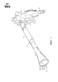
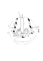
Фиг. 1 - перспективный вид пистолета-распылителя с вращающейся форсункой сверху и спереди в соответствии с настоящей полезной моделью.FIG. 1 is a perspective view of a spray gun with a rotating nozzle top and front in accordance with this utility model.
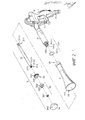
Фиг. 2 - перспективное объемное изображение пистолета-распылителя с вращающейся форсункой с пространственным разделением деталей в соответствии с настоящей полезной моделью.FIG. 2 is a perspective three-dimensional image of a spray gun with a rotating nozzle with a spatial separation of parts in accordance with this utility model.
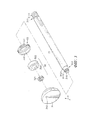
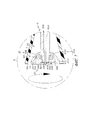
Фиг. 3 - перспективное объемное изображение с пространственным разделением деталей вращающегося формирователя струи пистолета-распылителя с вращающейся форсункой.FIG. 3 is a perspective three-dimensional image with a spatial separation of the details of the rotating shaper of the spray gun with a rotating nozzle.
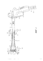
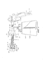
Фиг. 4 - вид пистолета-распылителя с вращающейся форсункой в разрезе, в соответствии с настоящей полезной моделью.FIG. 4 is a sectional view of a spray gun with a rotating nozzle in accordance with this utility model.
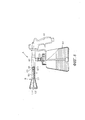
Фиг. 5 - увеличенное изображение узла А фиг. 4.FIG. 5 is an enlarged view of the assembly A of FIG. four.
Фиг. 6 - вид альтернативного образца пистолета-распылителя с вращающейся форсункой в разрезе, в соответствии с настоящей полезной моделью.FIG. 6 is a sectional view of an alternative sample of a spray gun with a rotating nozzle in accordance with the present utility model.
Фиг. 7 - увеличенное изображение узла В фиг. 6.FIG. 7 is an enlarged view of the assembly of FIG. 6.
Фиг. 8 - прототип пистолета-распылителя с вращающейся форсункой в соответствии с настоящей полезной моделью, вид в разрезе.FIG. 8 is a prototype of a spray gun with a rotating nozzle in accordance with this utility model, sectional view.
ПОДРОБНОЕ ОПИСАНИЕ ПОЛЕЗНОЙ МОДЕЛИDETAILED DESCRIPTION OF A USEFUL MODEL
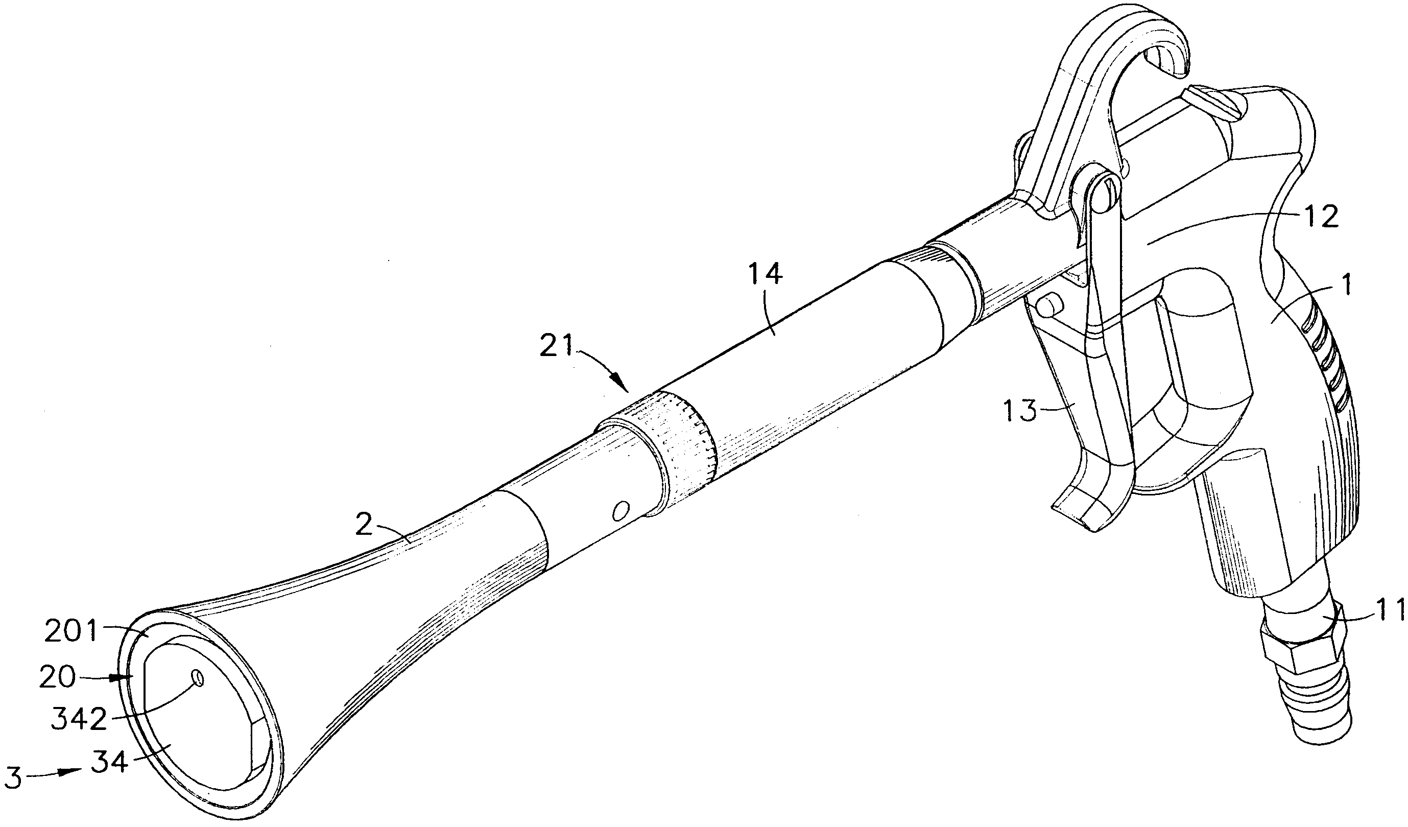
На фиг. 1-5 показаны перспективный вид пистолета-распылителя с вращающейся форсункой сверху и спереди, перспективное объемное изображение пистолета-распылителя с вращающейся форсункой с пространственным разделением деталей, перспективное объемное изображение с пространственным разделением деталей вращающегося формирователя струи пистолета-распылителя с вращающейся форсункой и вид пистолета-распылителя с вращающейся форсункой в разрезе. Как показано, пистолет-распылитель с вращающейся форсункой включает рукоять 1, соединительную трубку 2 и вращающийся формирователь 3 струи.In FIG. Figures 1-5 show a perspective view of a spray gun with a rotating nozzle top and front, a perspective three-dimensional image of a spray gun with a rotating nozzle with a spatial separation of parts, a perspective three-dimensional image with a spatial separation of parts of a rotating shaper of a spray gun with a rotating nozzle and a view of the gun- sectional view of a spray nozzle with a rotating nozzle. As shown, the spray gun with a rotating nozzle includes a
Рукоять 1 содержит воздухоприемную трубку 11 на ее нижней стороне, седло 12 клапана, расположенное на ее верхней стороне, спусковой крючок 13 и газоподводящую трубку 14. Спусковой крючок 13 предназначен для управления седлом 12 клапана с целью пропуска потока сжатого воздуха от внешнего источника через воздухоприемную трубку 11. Газоподводящая трубка 14 соединена своим задним концом с передним концом седла 12 клапана с другой стороны воздухоприемной трубки 11 и охватывает собой простирающийся в осевом направлении газоподводящий канал 140, сообщающийся с седлом 12 клапана и воздухоприемной трубкой 11. Далее, газоподводящая трубка 14 снабжена стыковочно-соединительным участком 141, расположенным на ее переднем конце, противоположном по отношению к седлу 12 клапана. Стыковочно-соединительный участок 141 представляет с собой стыковочно-соединительный резьбовой стержень 1411, выступающий из переднего конца газоподводящей трубки 14, охватывающей собой винтовое отверстие 1412, сообщающееся с газоподводящим каналом 140.The
Приставная трубка 2 включает стыковочно-соединительный концевой элемент 21, расположенный на одном из ее концов, стыковочно-соединительное винтовое отверстие 211, выполненное в стыковочно-соединительном концевом элементе 21, расширенное выпускное отверстие 201, расположенное на ее противоположном конце, и предусмотренную в нем аксиально расположенную аккомодационную полость 20, сообщающуюся со стыковочно-соединительным винтовым отверстием 211 и отверстием 201.The attached
Вращающийся формирователь 3 струи включает газопроводящую трубку 31, подшипник 32, соединительную муфту 33 и вращающуюся форсунку 34. Газопроводящая трубка 31 включает газопроводящий канал, проходящий в осевом направлении через ее противоположные передний и задний концы, соединительный концевой элемент 311, имеющийся на заднем конце, то есть резьбовой участок 3111, простирающийся назад в осевом направлении от заднего конца газопроводящей трубки 31, и соединительный участок 312, имеющийся на переднем конце. Соединительный участок 312 включает соединительный цилиндрический хвостовик 3121, простирающийся вперед в осевом направлении от переднего конца газопроводящей трубки 31, и трубчатый резьбовой стержень 3122, простирающийся вперед в осевом направлении от соединительного цилиндрического хвостовика 3121. Подшипник 32 снабжен осевым отверстием 320, в которое вставлен соединительный цилиндрический хвостовик 3121 соединительного участка 312 газопроводящей трубки 31. Далее, стопорная гайка 321 навинчена на трубчатый резьбовой стержень 3122 для предотвращения спадания подшипника 32 с соединительного цилиндрического хвостовика 3121. Соединительная муфта 33 установлена на газопроводящую трубку 31, причем посадочная выемка 330 жестко соединена с наружным кольцом 322 подшипника 32, а наружная резьба 331 расположена вокруг периферии муфты. Вращающаяся форсунка 34 включает внутреннюю резьбу 341, имеющуюся с одной ее стороны и входящую в зацепление с наружной резьбой 331 соединительной муфты 33, газоаккумулирующую камеру 340, предусмотренную в форсунке и простирающуюся внутрь от наружной резьбы 331, и косое отверстие 342, простирающееся косо вперед от газоаккумулирующей камеры 340 наружу от вращающейся форсунки 34, с эксцентричным расположением.Rotating jet former 3 includes a
При сборке, присоедините воздухоприемную трубку 11 рукояти 1 к внешнему источнику высокого давления воздуха. При этом пользователь может воздействовать на спусковой крючок 13 рукояти 1 для управления поступлением сжатого воздуха от внешнего источника высокого давления воздуха через воздухоприемную трубку 11. Далее, уплотнительное кольцо 1413 надевают на стыковочно-соединительный резьбовой стержень 1411 стыковочно-соединительного участка 141 газоподводящей трубки 14 рукояти 1, а затем стыковочно-соединительное винтовое отверстие 211 стыковочно-соединительного концевого элемента 21 приставной трубки 2 навинчивают на стыковочно-соединительный резьбовой стержень 1411 стыковочно-соединительного участка 141 газоподводящей трубки 14 и прижимают к уплотнительному кольцу 1413 перед стыковочно-соединительным концевым элементом 21 приставной трубки 2. Сверх того, перед скреплением стыковочно-соединительного винтового отверстия 211 приставной трубки 2 со стыковочно-соединительным резьбовым стержнем 1411 газоподводящей трубки 14 резьбовой участок 3111 соединительного концевого элемента 311 газопроводящей трубки 31 вращающегося формирователя 3 струи ввинчивают в винтовое отверстие 1412 стыковочно-соединительного участка 141 газоподводящей трубки 14, приставную трубку 2 размещают с передней стороны газоподводящей трубки 14 вокруг газопроводящей трубки 31, а соединительный участок 312 газопроводящей трубки 31 оставляют в расширенном выпускном отверстии 201 приставной трубки 2 в состоянии ожидания, после чего подшипник 32, соединительная муфта 33 и вращающаяся форсунка 34 могут быть установлены на соединительный участок 312 газопроводящей трубки 31 и оставлены свободно вращающимися в расширенном выпускном отверстии 201 с наружной стороны аккомодационной полости 20 приставной трубки 2. Таким образом, рукоять 1, приставная трубка 2 и вращающийся формирователь 3 струи оказываются собранными, чтобы составить пистолет-распылитель с вращающейся форсункой в соответствии с настоящей полезной моделью.When assembling, attach the
При пользовании, присоедините воздухоприемную трубку 11 рукояти 1 к внешнему источнику высокого давления воздуха (например, к воздушному компрессору), а затем воздействуйте на спусковой крючок 13 рукояти 1 для управления поступлением сжатого воздуха от внешнего источника высокого давления воздуха через воздухоприемную трубку 11 и воздухоподающий канал 121 седла 12 клапана в газоподводящий канал 140 газоподводящей трубки 14, побуждая входящий поток сжатого воздуха проходить через стыковочно-соединительный участок 141 газоподводящей трубки 14 и газопроводящий канал 310 газопроводящей трубки 31 вращающегося формирователя 3 струи в газоаккумулирующую камеру 340 вращающейся форсунки 34 и затем проходить из газоаккумулирующей камеры 340 через отверстие 342 форсунки в наружную среду пистолета-распылителя. Одновременно вращающаяся форсунка 34 и соединительная муфта 33 начинают вращаться на наружном кольце 322 подшипника 32 от давления проходящего через них потока сжатого воздуха, и таким образом сильная струя воздуха непрерывно закручивается и извергается на поверхность объекта (кузов автомобиля или наружное остекление здания) с целью удаления водяной протравы или пыли с поверхности объекта без причинения повреждений.When using, attach the
Кроме того, приставная трубка 2, присоединенная к газоподводящей трубке 14 рукояти 1, может быть рупорообразной, обычной или полигональной трубой.In addition, the
На фиг. 6 и 7 показаны вид альтернативного образца пистолета-распылителя с вращающейся форсункой в разрезе, в соответствии с настоящей полезной моделью, и увеличенное изображение узла B фиг. 6. Этот альтернативный образец целесообразен для извержения закрученного потока водного аэрозоля. Согласно этому альтернативному образцу газоподводящая трубка 14 рукояти 1 является Т-образной трехходовой трубой, содержащей нижнюю соединительную трубку 142, расположенную вертикально с ее нижней стороны и сообщающуюся с газоподводящим каналом 140 для подсоединения водяного бачка 1421. Далее, погружная трубка 1422 подсоединена к нижней соединительной трубке 142 и свисает в водяной бачок 1421 вблизи нижней стенки водяного бачка 1421. Далее, водоподающая трубка 1423 вмонтирована в газоподводящий канал 140 газоподводящей трубки 14 и простирается от нижней соединительной трубки 142 через газопроводящий канал 310 газопроводящей трубки 31 вращающегося формирователя 3 струи в газоаккумулирующую камеру 340 вращающейся форсунки 34 и завершается водовыпускным концом 1424, вставленным в сквозное отверстие 343, расположенное во вращающейся форсунке 34, и проходящим сквозь переднюю поверхность 344 вращающейся форсунки 34. Диаметр сквозного отверстия 343 больше наружного диаметра водовыпускного конца 1424 водоподающей трубки 1423. При пользовании, присоедините воздухоприемную трубку 11 рукояти 1 к внешнему источнику высокого давления воздуха (к воздушному компрессору) с помощью нагнетательного шланга 111 высокого давления, а затем воздействуйте на спусковой крючок 13 рукояти 1 для управления поступлением сжатого воздуха от внешнего источника высокого давления воздуха через воздухоприемную трубку 11 и воздухоподающий канал 121 седла 12 клапана в газоподводящий канал 140 газоподводящей трубки 14, побуждая входящий поток сжатого воздуха проходить через стыковочно-соединительный участок 141 газоподводящей трубки 14 и газопроводящий канал 310 газопроводящей трубки 31 вращающегося формирователя 3 струи в газоаккумулирующую камеру 340 вращающейся форсунки 34 и затем проходить из газоаккумулирующей камеры 340 через отверстие 342 форсунки в наружную среду пистолета-распылителя. Одновременно вращающаяся форсунка 34 и соединительная муфта 33 начинают вращаться на наружном кольце 322 подшипника 32 от давления проходящего через них потока сжатого воздуха, и таким образом сильная струя воздуха непрерывно закручивается и эжектируется из пистолета-распылителя. Когда входящий поток сжатого воздуха проходит через соединительный участок 312 газопроводящей трубки 31 и через сквозное отверстие 343 вращающейся форсунки 34, в сквозном отверстии 343 создается эффект Вентури, вызывающий засасывание имеющейся в водяном бачке 1421 воды через погружную трубку 1422 и нижнюю соединительную трубку 142 в водоподающую трубку 1423 с последующим выводом ее из водоподающей трубки 1423 через водовыпускной конец 1424. Когда поток жидкости эжектируется из водовыпускного конца 1424, сжатый воздух непрерывно направляется в газоаккумулирующую камеру 340 вращающейся форсунки 34 и эжектируется из косого отверстия 342 и из кольцевого зазора в сквозном отверстии 343 вокруг водовыпускного конца 1424, заставляя поток жидкости, извергаемый из водовыпускного конца 1424, превращаться в аэрозоль. Таким образом, когда пользователь приводит в движение спусковой крючок 13 рукояти 1, чтобы позволить потоку сжатого воздуха поступить от внешнего источника высокого давления воздуха через воздухоприемную трубку 11 в газоподводящую трубку 14 и газопроводящую трубку 31 вращающегося формирователя 3 струи и в газоаккумулирующую камеру 340 вращающейся форсунки 34, а затем поступить из газоаккумулирующей камеры 340 через косое отверстие 342 форсунки и кольцевой зазор в сквозном отверстии 343 вокруг водовыпускного конца 1424 по направлению к наружной стороне пистолета-распылителя, одновременно поток жидкости исторгается из водовыпускного конца 1424 и превращаться в аэрозоль. Когда сильная струя сжатого воздуха эжектируется из кольцевого зазора в сквозном отверстии 343 вокруг водовыпускного конца 1424, чтобы превратить извергнутый поток воздуха в аэрозоль, сжатый воздух одновременно эжектируется из косого отверстия 342 форсунки, делая аэрозоль более мелким.In FIG. 6 and 7 show a sectional view of an alternative sample of a spray gun with a rotating nozzle in accordance with the present utility model, and an enlarged view of the assembly B of FIG. 6. This alternative sample is suitable for erupting a swirling stream of water aerosol. According to this alternative example, the
Как показано выше, резьбовой участок 3111 газопроводящей трубки 31 вращающегося формирователя 3 струи ввинчен в винтовое отверстие 1412 стыковочно-соединительного участка 141; подшипник 32 установлен на соединительный цилиндрический хвостовик 3121 соединительного участка 312 газопроводящей трубки 31; стопорная гайка 321 навинчена на трубчатый резьбовой стержень 3122 соединительного участка 312 газопроводящей трубки 31. Далее, диаметр стопорной гайки 321 больше внутреннего диаметра осевого отверстия 320 подшипника 32. Таким образом, подшипник 32 зафиксирован на своем месте стопорной гайкой 321, и предохранен от спадания с соединительного цилиндрического хвостовика 3121. Далее, посадочная выемка 330 соединительной муфты 33 жестко соединена с наружным кольцом 322 подшипника 32; внутренняя резьба 341 вращающейся форсунки 34 находится в зацеплении с наружной резьбой 331 соединительной муфты 33; газопроводящая трубка 31 вращающегося формирователя 3 струи находится в висячем положении в аккомодационной полости 20 приставной трубки 2; вращающаяся форсунка 34 установлена свободно вращающейся на конце газопроводящей трубки 31 в отверстии 201 приставной трубки 2. Когда сжатый воздух подается в газопроводящий канал 310 газопроводящей трубки 31, он аккумулируется в газоаккумулирующей камере 340 вращающейся форсунки 34 и затем выталкивается из косого отверстия 342 вращающейся форсунки 34, вызывая вращение вращающейся форсунки 34 с соединительной муфтой 33 и наружным кольцом 322 подшипника 32. Таким образом, когда поток сжатого воздуха подается через газопроводящий канал 310 и выталкивается из косого отверстия 342 форсунки, вращающаяся форсунка 34 приводится во вращение в отверстии 201 приставной трубки 2, в то время как газопроводящая трубка 31 остается неподвижной в аккомодационной полости 20 приставной трубки 2, не вызывая возникновения центробежной силы, которая могла бы вытолкнуть газопроводящую трубку 31 из приставной трубки 2; таким образом увеличена конструкционная прочность приставной трубки 2 и вращающегося формирователя 3 струи. Далее, водовыпускной конец 1424 водоподающей трубки 1423 вставлен в сквозное отверстие 343 вращающейся форсунки 34 вращающегося формирователя 3 струи, а погружная трубка 1422 присоединена к нижней соединительной трубке 142 и опущена в водяной бачок 1421 для высасывания содержащейся в нем воды. Таким образом, когда поток жидкости засасывается в погружную трубку 1422 и направляется через водоподающую трубку 1423 и водовыпускной конец 1424 по направлению к наружной стороне сквозного отверстия 343 вращающейся форсунки 34, эжектируемый сжатый воздух, истекающий из косого отверстия 342 и кольцевого зазора в сквозном отверстии 343 вокруг водовыпускного конца 1424, заставляет жидкость, эжектируемую из водовыпускного конца 1424, превращаться в аэрозоль. Далее, стопорная гайка 321 навинчена на трубчатый резьбовой стержень 3122 соединительного участка 312 газопроводящей трубки 31 вращающегося формирователя 3 струи, чтобы удерживать подшипник 32 и соединительную муфту 33 на своем месте, предотвращая спадание подшипника 32 и соединительной муфты 33 с соединительного участка 312. Далее, внутренняя резьба 341 вращающейся форсунки 34 находится в зацеплении с наружной резьбой 331 соединительной муфты 33. Когда вращающаяся форсунка 34 и соединительная муфта 33 приводятся во вращение вместе с подшипником 32, направление вращения вращающейся форсунки 34 и соединительной муфты 33 является противоположным направлению завинчивания между вращающейся форсункой 34 и соединительной муфтой 33, и, таким образом, центробежная сила, возникающая во время вращения вращающейся форсунки 34 и соединительной муфты 33, не вызывает разъединения между вращающейся форсункой 34 и соединительной муфтой 33. Таким образом, при пользовании компоновочный узел вращающейся форсунки 34, подшипника 32 и соединительной муфты 33 не будет вытолкнут из аккомодационной полости 20 приставной трубки 2, обеспечивая высокий уровень надежности работы пистолета-распылителя и уменьшая степень опасности при пользовании.As shown above, the threaded
Как описано выше, приставная трубка 2 и вращающийся формирователь 3 струи присоединены к газоподводящей трубке 14 рукояти 1 посредством ввинчивания резьбового участка 3111 соединительного концевого элемента 311 газопроводящей трубки 31 вращающегося формирователя 3 струи в винтовое отверстие 1412 стыковочно-соединительного резьбового стержня 1411 стыковочно-соединительного участка 141 газоподводящей трубки 14 и затем навинчивания стыковочно-соединительное винтовое отверстие 211 стыковочно-соединительного концевого элемента 21 приставной трубки 2 на стыковочно-соединительный резьбовой стержень 1411 стыковочно-соединительного участка 141 газоподводящей трубки 14, а затем подшипник 32, соединительная муфта 33 и вращающаяся форсунка 34 установлены на соединительный участок 312 газопроводящей трубки 31 вращающегося формирователя 3 струи. При пользовании воздухоприемную трубку 11 рукояти 1 подсоединяют к внешнему источнику высокого давления воздуха. Когда посредством воздействия на спусковой крючок 13 производится открывание седла 12 клапана, сжатый воздух направляется через воздухоприемную трубку 11 рукояти 1 и газоподводящий канал 140 газоподводящей трубки 14 в газопроводящую трубку 31 вращающегося формирователя 3 струи и в газоаккумулирующую камеру 340 вращающейся форсунки 34. Затем сжатый воздух выталкивается из косого отверстия 342 вращающейся форсунки 34. Когда поток сжатого воздуха выталкивается из косого отверстия 342 вращающейся форсунки 34, центробежная сила, произведенная таким образом, заставляет вращающуюся форсунку 34 вращаться в отверстии 201 приставной трубки 2. Далее, водяной бачок 1421 подсоединен к нижней соединительной трубке 142 газоподводящей трубки 14, а погружная трубка 1422 подсоединена к нижней соединительной трубке 142 и опущена в водяной бачок 1421. Таким образом, когда закрученный поток сжатого воздуха эжектируется из кольцевого зазора в сквозном отверстии 343 вокруг водовыпускного конца 1424, поток жидкости засасывается в погружную трубку 1422 и направляется через водоподающую трубку 1423 и водовыпускной конец 1424 по направлению к наружной стороне сквозного отверстия 343 вращающейся форсунки 34, и жидкость, вытолкнутая из водовыпускного конца 1424, затем превращается в аэрозоль; одновременно сжатый воздух эжектируется из косого отверстия 342, делая аэрозоль более мелким.As described above, the
Таким образом, полезная модель направлена на создание пистолета-распылителя с вращающейся форсункой, включающего рукоять, которая включает седло клапана, спусковым крючком, и газоподводящую трубку, отходящую от седла клапана и оканчивающуюся стыковочно-соединительным участком, приставную трубку, присоединенную к стыковочно-соединительному участку газоподводящей трубки, и вращающийся формирователь струи, включающий газопроводящую трубку, подсоединенную к стыковочно-соединительному участку газоподводящей трубки и находящуюся в висячем положении в аккомодационной полости приставной трубки, подшипник, соединительную муфту и вращающуюся форсунку, установленные на соединительный участок газопроводящей трубки. При воздействии на спусковой крючок рукояти сжатый воздух направляется через воздухоприемную трубку рукояти в газопроводящую трубку вращающегося формирователя струи и затем выталкивается из косого отверстия вращающейся форсунки, и одновременно производится центробежная сила, которая заставляет вращающуюся форсунку вращаться в выпускном отверстии приставной трубки, и таким образом закрученный поток сжатого воздуха эжектируется из пистолета-распылителя. Далее, газоподводящая трубка может быть скомпонована с нижней соединительной трубкой для подсоединения водяного бачка, водоподающая трубка вмонтирована в газоподводящий канал газоподводящей трубки и простирается от нижней соединительной трубки через газопроводящий канал газопроводящей трубки вращающегося формирователя струи в газоаккумулирующую камеру вращающейся форсунки и завершается водовыпускным концом, вставленным в сквозное отверстие во вращающейся форсунке. Таким образом, когда закрученный поток сжатого воздуха эжектируется из кольцевого зазора в сквозном отверстии вокруг водовыпускного конца, поток жидкости засасывается в нижнюю соединительную трубку газоподводящей трубки и водоподающей трубки и эжектируется из водовыпускного конца водоподающей трубки, и жидкость, вытолкнутая из водовыпускного конца, затем превращается в аэрозоль; одновременно сжатый воздух эжектируется из косого отверстия, делая аэрозоль более мелким.Thus, the utility model is aimed at creating a spray gun with a rotating nozzle, including a handle that includes a valve seat, a trigger, and a gas supply pipe extending from the valve seat and ending with a docking and connecting section, an attached tube attached to the docking and connecting section a gas supply tube, and a rotating jet former comprising a gas conduit connected to the docking and connecting portion of the gas supply tube and located in accommodative state than in the cavity Adjacent tubes bearing the coupling and rotating a nozzle mounted on the connecting portion of the gas conducting tube. When the handle is acted upon by the handle, the compressed air is directed through the handle air intake tube into the gas conduit of the rotating jet former and then is pushed out of the oblique hole of the rotating nozzle, and at the same time a centrifugal force is produced which causes the rotating nozzle to rotate in the outlet of the attached tube, and thus the swirl compressed air is ejected from the spray gun. Further, the gas supply pipe can be arranged with the lower connecting pipe to connect the water tank, the water supply pipe is mounted in the gas supply channel of the gas supply pipe and extends from the lower connecting pipe through the gas supply channel of the gas supply pipe of the rotational jet former into the gas storage chamber of the rotating nozzle and ends with the water supply end through hole in rotating nozzle. Thus, when a swirling stream of compressed air is ejected from the annular gap in the through hole around the water outlet, the liquid flow is sucked into the lower connecting pipe of the gas supply pipe and the water supply pipe and ejected from the water outlet end of the water supply pipe, and the liquid pushed out of the water outlet end is then turned into spray can; at the same time, compressed air is ejected from the oblique opening, making the aerosol finer.
В целях иллюстрации здесь дано подробное описание вариантов полезной модели, однако возможны ее различные модификации и усовершенствования без нарушения сущности и объема полезной модели. Следовательно, данная полезная модель не должна ограничиваться ничем иным, как только прилагаемыми пунктами формулы полезной модели.For purposes of illustration, a detailed description of the utility model options is given, however, various modifications and improvements are possible without violating the essence and scope of the utility model. Therefore, this utility model should not be limited to anything other than the attached claims of the utility model formula.
Claims (10)
Applications Claiming Priority (2)
| Application Number | Priority Date | Filing Date | Title |
|---|---|---|---|
| TW104105598A TWI586436B (en) | 2015-02-17 | 2015-02-17 | The construction of the revolving gun |
| TW104105598 | 2015-02-17 |
Publications (1)
| Publication Number | Publication Date |
|---|---|
| RU166314U1 true RU166314U1 (en) | 2016-11-20 |
Family
ID=55641881
Family Applications (1)
| Application Number | Title | Priority Date | Filing Date |
|---|---|---|---|
| RU2015147550/05U RU166314U1 (en) | 2015-02-17 | 2015-11-06 | SPRAY GUN WITH ROTATING NOZZLE |
Country Status (7)
| Country | Link |
|---|---|
| US (1) | US9751098B2 (en) |
| DE (1) | DE102015107764B4 (en) |
| FR (1) | FR3032631B3 (en) |
| GB (1) | GB2537016A (en) |
| IT (1) | ITUB201566393U1 (en) |
| RU (1) | RU166314U1 (en) |
| TW (1) | TWI586436B (en) |
Families Citing this family (13)
| Publication number | Priority date | Publication date | Assignee | Title |
|---|---|---|---|---|
| US9823040B1 (en) * | 2016-08-23 | 2017-11-21 | Shih-Che Hu | Gun barrel unit for a toy gun |
| CN107512248B (en) * | 2017-07-17 | 2023-08-01 | 吴寿林 | Vehicle cleaning and maintenance equipment |
| FR3072347B1 (en) * | 2017-10-16 | 2019-11-08 | Heurtaux S.A.S. | DEVICE FOR WASHING A VEHICLE BY PROJECTING HIGH-PRESSURE WASHING LIQUID |
| US10259002B1 (en) * | 2018-04-09 | 2019-04-16 | Grain Point Enterprise Limited | Spray-gun apparatus |
| EP4247572B1 (en) * | 2020-11-17 | 2026-01-28 | Engineered Controls International, LLC | Cleaning nozzle for cryogenic fluid fueling receptacle |
| CN116507430A (en) * | 2020-11-17 | 2023-07-28 | 国际工程控制公司 | Cleaning nozzle for cryogenic fluid fueling receptacle |
| US11732887B1 (en) * | 2021-07-02 | 2023-08-22 | Placer Union High School District | Brush burning tool |
| CN113503005B (en) * | 2021-07-05 | 2022-07-01 | 北京建工四建工程建设有限公司 | High-adhesion paint spraying unit and paint spraying device |
| USD1057090S1 (en) * | 2021-11-08 | 2025-01-07 | Energizer Auto, Inc. | Foam sprayer |
| USD1024271S1 (en) * | 2021-11-08 | 2024-04-23 | Energizer Auto, Inc. | Foam sprayer |
| PL442253A1 (en) * | 2022-09-12 | 2024-03-18 | Erko Spółka Z Ograniczoną Odpowiedzialnością Spółka Komandytowa | Computer-aided method of producing busbars, system of devices for implementing this method and device for plastic shaping of flat bars by this method |
| PL245918B1 (en) * | 2022-10-13 | 2024-10-28 | 3N Solutions Spolka Z Ograniczona Odpowiedzialnoscia | Lance of the cleaning kit for medium voltage power equipment |
| USD1100141S1 (en) * | 2025-03-30 | 2025-10-28 | Shenzhen Zero Zero Hair Automotive Supplies Co., Ltd | Car washing gun |
Family Cites Families (34)
| Publication number | Priority date | Publication date | Assignee | Title |
|---|---|---|---|---|
| US2983452A (en) * | 1958-06-12 | 1961-05-09 | Virgual T Lindbloom | Rotary sprayer |
| US3868949A (en) * | 1973-08-08 | 1975-03-04 | Arneson Prod Inc | Hydromassage device |
| US4704826A (en) * | 1981-06-26 | 1987-11-10 | Kirkland Wyatt S | Spin-blast tool |
| US4523340A (en) * | 1982-12-20 | 1985-06-18 | Watkins Manufacturing Co. | Means providing moving water stream ejecting into spa tank |
| US4716604A (en) * | 1985-09-18 | 1988-01-05 | Watkins Manufacturing Co. | Spa with moving jets |
| US4689839A (en) * | 1985-11-12 | 1987-09-01 | Henkin Melvyn Lane | Tap water powered hydrotherapy method and apparatus |
| US4821961A (en) * | 1988-03-31 | 1989-04-18 | Nlb Corp. | Self-rotating nozzle |
| US5060862A (en) * | 1990-01-19 | 1991-10-29 | Butterworth Jetting Systems, Inc. | Magnetic speed control for self-propelled swivel |
| US5104043A (en) * | 1990-01-19 | 1992-04-14 | Butterworth Jetting Systems, Inc. | Magnetic speed control for self-propelled swivel |
| US5232161A (en) * | 1991-05-13 | 1993-08-03 | Goldblatt Tool Company | Texture material application device |
| JP2514135B2 (en) * | 1991-12-06 | 1996-07-10 | 安全自動車株式会社 | Highly convergent jet nozzle device |
| US5284298A (en) * | 1993-04-13 | 1994-02-08 | Fluid Controls Inc. | Fluid-conducting swivel and method |
| US6193169B1 (en) * | 1993-08-26 | 2001-02-27 | Spraying Systems Deutschland Gmbh | Rotating spray nozzle with controlled braking action |
| US5909848A (en) * | 1998-07-17 | 1999-06-08 | Stoneage, Inc. | High pressure liquid rotary nozzle with coil spring retarder |
| JP2004321844A (en) * | 2003-04-21 | 2004-11-18 | Ransburg Ind Kk | Rotary atomizing type coating machine |
| US7458485B2 (en) * | 2005-05-23 | 2008-12-02 | Tropical Ventures Llc | Water gun amusement devices and methods of using the same |
| ATE469703T1 (en) * | 2006-08-11 | 2010-06-15 | Ulrich Simpfendoerfer | CLEANING NOZZLE |
| US8480011B2 (en) * | 2007-09-04 | 2013-07-09 | Dehn's Innovations, Llc | Nozzle system and method |
| US8056830B1 (en) * | 2009-01-02 | 2011-11-15 | Jeff M Pedersen | Spinner tip shower head |
| EP2221110A1 (en) * | 2009-02-19 | 2010-08-25 | Double Dynasty Co., Ltd. | Rotary spray gun |
| TWM380171U (en) * | 2009-11-03 | 2010-05-11 | Grain Point Entpr Ltd | Structure of spraying gun |
| US9321067B2 (en) * | 2010-07-08 | 2016-04-26 | Federal Signal Corporation | Seal cartridge for a rotating nozzle assembly |
| TW201244827A (en) * | 2011-05-11 | 2012-11-16 | Strong Fortress Tool Co Ltd | Rotary spraying device |
| TWM418736U (en) * | 2011-09-01 | 2011-12-21 | Strong Fortress Tool Co Ltd | Spray gun apparatus |
| DE202011105869U1 (en) * | 2011-09-16 | 2011-10-24 | 3St Industry Co., Ltd. | Speed adjustment mechanism for a rotary spray gun |
| US9144810B2 (en) * | 2012-07-04 | 2015-09-29 | Christopher John Bosua | Atomizing nozzle assembly for pneumatically operated cleaning equipment |
| TW201406465A (en) * | 2012-08-10 | 2014-02-16 | Strong Fortress Tool Co Ltd | Cyclotron |
| US20140061334A1 (en) * | 2012-09-05 | 2014-03-06 | Ying-Chieh Liao | Spray gun |
| US9399230B2 (en) * | 2014-01-16 | 2016-07-26 | Nlb Corp. | Rotating fluid nozzle for tube cleaning system |
| US20150266041A1 (en) * | 2014-03-24 | 2015-09-24 | Ying-Chieh Liao | Spray gun |
| TWM486493U (en) * | 2014-05-26 | 2014-09-21 | Neutek Internat Inc | Liquid storage device for rotary spray gun |
| TWI533934B (en) * | 2014-07-01 | 2016-05-21 | Qing-Nan Chen | Air guide rotary spray device and air guide rotary sprayer |
| US20160339458A1 (en) * | 2015-05-19 | 2016-11-24 | Neutek International Inc. | Structure of gyrating nozzle spray gun |
| DE202015102785U1 (en) * | 2015-05-29 | 2015-06-17 | Neutek International Inc. | Improved construction of a rotary nozzle spray gun |
-
2015
- 2015-02-17 TW TW104105598A patent/TWI586436B/en not_active IP Right Cessation
- 2015-05-11 US US14/709,146 patent/US9751098B2/en not_active Expired - Fee Related
- 2015-05-18 DE DE102015107764.7A patent/DE102015107764B4/en not_active Expired - Fee Related
- 2015-08-31 IT ITUB2015U066393U patent/ITUB201566393U1/en unknown
- 2015-09-16 FR FR1558674A patent/FR3032631B3/en not_active Expired - Fee Related
- 2015-11-06 RU RU2015147550/05U patent/RU166314U1/en not_active IP Right Cessation
-
2016
- 2016-02-05 GB GB1602111.5A patent/GB2537016A/en not_active Withdrawn
Also Published As
| Publication number | Publication date |
|---|---|
| US20160332175A1 (en) | 2016-11-17 |
| TWI586436B (en) | 2017-06-11 |
| GB2537016A (en) | 2016-10-05 |
| TW201630664A (en) | 2016-09-01 |
| DE102015107764A1 (en) | 2016-11-24 |
| GB201602111D0 (en) | 2016-03-23 |
| US9751098B2 (en) | 2017-09-05 |
| ITUB201566393U1 (en) | 2017-03-03 |
| FR3032631B3 (en) | 2017-04-28 |
| FR3032631A3 (en) | 2016-08-19 |
| DE102015107764B4 (en) | 2017-11-09 |
Similar Documents
| Publication | Publication Date | Title |
|---|---|---|
| RU166314U1 (en) | SPRAY GUN WITH ROTATING NOZZLE | |
| US20160339458A1 (en) | Structure of gyrating nozzle spray gun | |
| RU95562U1 (en) | SPRAYING GUN WITH ROTATING BENT TUBE | |
| CN108296042A (en) | A kind of spray nozzle of cleaning machine component | |
| JP3198554U (en) | Structure of rotary cleaning gun | |
| CN204602450U (en) | The structure of the rotary spray gun | |
| CN221356742U (en) | Water outlet atomization structure of floor brush of floor scrubber | |
| CN203803682U (en) | Large device cleaning machine | |
| CN113712454B (en) | Shower gel spray head of shower device | |
| CN110508577A (en) | A kind of quick bottle washer of hand-held | |
| JP2016203117A (en) | Structure of rotary washing gun | |
| CN1741857A (en) | Nozzle and ejector | |
| CN214637446U (en) | Multifunctional environment-friendly spray gun for automobile coating repair | |
| CN209829302U (en) | Shower nozzle | |
| JP3198555U (en) | Structure of rotary cleaning gun | |
| CN109482547A (en) | A kind of cleaning machine | |
| CN204956431U (en) | Multi -functional portable carwash squirt | |
| CN2327452Y (en) | Washing jet | |
| CN208332399U (en) | Cleaning sprayer and kitchen ventilator | |
| CN208411684U (en) | A kind of portable car cleaner | |
| JP2008114211A (en) | Fluid ejection device | |
| CN208377012U (en) | Pneumatic water aspirator peculiar to vessel | |
| CN222739431U (en) | 360 Rotatable foam cleaning shower nozzle of degree | |
| DE202015102533U1 (en) | Rotating nozzles spray gun | |
| CN209287828U (en) | A kind of nozzle ring assemblies inner hole cleaning device |
Legal Events
| Date | Code | Title | Description |
|---|---|---|---|
| MM9K | Utility model has become invalid (non-payment of fees) |
Effective date: 20191107 |