RU158137U1 - SYSTEM OF PROFILES FOR MANUFACTURE OF THE DOOR OPENING BOX - Google Patents
SYSTEM OF PROFILES FOR MANUFACTURE OF THE DOOR OPENING BOX Download PDFInfo
- Publication number
- RU158137U1 RU158137U1 RU2015116329/12U RU2015116329U RU158137U1 RU 158137 U1 RU158137 U1 RU 158137U1 RU 2015116329/12 U RU2015116329/12 U RU 2015116329/12U RU 2015116329 U RU2015116329 U RU 2015116329U RU 158137 U1 RU158137 U1 RU 158137U1
- Authority
- RU
- Russia
- Prior art keywords
- profiles
- profile
- wall
- opening
- additional element
- Prior art date
Links
Images


Abstract
1. Система профилей для изготовления коробки проёма двери, содержащая два профиля, связанные между собой через плоский доборный элемент, установленный в открытых пазах, несомых профилями навстречу друг другу, отличающаяся тем, что стенки открытых пазов выполнены на внешних поверхностях профилей со стороны середины проёма, а в направленных друг к другу стенках профилей, выполнены отверстия и/или канавка по длине профиля, связанные разъёмным креплением для обжатия стенки проёма в направлении параллельном плоскости доборного элемента, при этом, по меньшей мере, в одном профиле параллельно плоскости доборного элемента выполнен уступ с отверстиями для разъёмного крепежа к стенке проёма в направлении перпендикулярном плоскости доборного элемента.2. Система профилей по п. 1, отличающаяся тем, что между профилями на стенке проёма закреплён промежуточный профиль для разъёмного крепления к нему другого профиля и обжатия стенки проёма параллельно плоскости доборного элемента.3. Система профилей по п. 1, отличающаяся тем, что в качестве разъёмного крепления использованы саморезы с декоративной маскировкой в виде нащельника, крышки или накладки.1. A system of profiles for the manufacture of a doorway box containing two profiles interconnected through a flat additional element installed in open grooves carried by the profiles facing each other, characterized in that the walls of the open grooves are made on the outer surfaces of the profiles from the side of the middle of the opening, and in the walls of the profiles directed to each other, holes and / or a groove are made along the length of the profile, connected by a detachable fastening to compress the wall of the opening in the direction parallel to the plane of the additional element, with this, at least in one profile parallel to the plane of the additional element is made ledge with holes for detachable fasteners to the wall of the opening in the direction perpendicular to the plane of the additional element. 2. A profile system according to claim 1, characterized in that an intermediate profile is fixed between the profiles on the wall of the aperture for detachably attaching another profile thereto and compressing the aperture wall parallel to the plane of the additional element. 3. The profile system according to claim 1, characterized in that as a detachable fastening, self-tapping screws with decorative disguise in the form of a filler, cover or lining are used.
Description
Полезная модель относится к области жилищного строительства, в частности, к конструкции межкомнатных дверей, в которых коробки проемов изготовлены с применением профилей, выполненных из алюминия или его сплавов методом экструзии.The utility model relates to the field of housing, in particular, to the design of interior doors, in which apertures are made using profiles made of aluminum or its alloys by extrusion.
Известен способ крепления коробки двери или ворот к стене проема здания, включающий сборку коробки из его элементов, введение закладных деталей в пазы боковых стоек и верхней перекладины коробки, установку коробки в проеме стены здания, крепление закладных деталей к проему стены здания и последующую фиксацию коробки посредством фиксирующих элементов (а.с. N 293116, E06B 1/60, СССР, 1969 г.). Для обеспечения плотного сопряжения приклеиваемых деталей между коробкой и полкой уголка забивают клиновой элемент. Торец уголка и клин не должны выступать за внутреннюю плоскость коробки. Для дверных и оконных коробок обычных габаритов предусмотрены четыре узла крепления, по два на каждой боковой стороне. Для оконных коробок малой высоты возможно применение двух узлов крепления.A known method of fastening a door or gate box to a wall of an opening of a building, including assembling a box of its elements, inserting embedded parts into the grooves of the side racks and the upper crossbar of the box, installing the box in the opening of the building wall, fixing the embedded parts to the opening of the building wall and subsequently fixing the box by fixing elements (A.S. N 293116, E06B 1/60, USSR, 1969). To ensure a tight fit of the glued parts between the box and the corner shelf, the wedge element is driven. The corner end and the wedge should not protrude beyond the inner plane of the box. For door and window frames of normal dimensions, four attachment points are provided, two on each side. For window frames of small height, two attachment points are possible.
Недостаток известного способа заключается в том, что известное техническое решение не может быть использовано для повторной установки коробки.The disadvantage of this method is that the known technical solution cannot be used to reinstall the box.
Известен также способ крепления двери или ворот к стене проема здания, включающий изготовление фиксирующих элементов на поверхности коробки непосредственно из материала коробки и последующую фиксацию коробки к стене проема здания (патент США N 2189216, 1940 г., кл. 72-98).There is also a method of attaching a door or gate to a wall of an opening of a building, including the manufacture of fixing elements on the surface of the box directly from the material of the box and subsequent fixing of the box to the wall of the opening of the building (US patent N 2189216, 1940, class 72-98).
Недостаток известного способа заключается в том, что известное техническое решение не обеспечивает крепление коробки в готовых проемах с повышенными механическими свойствами материала проема. Это объясняется тем, что коробку с отогнутыми фиксирующими элементами устанавливают в место будущего проема, а фиксацию коробки в проеме стены осуществляют путем монтажа стен по наружному периметру коробки, т.е. предлагаемое техническое решение, как правило, реализуется непосредственно при строительстве (монтаже) стен строительных объектов. Это объясняется также тем, что коробку, по известному техническому решению, можно закрепить посредством фиксирующих элементов к поверхности готового проема, если материал проема является податливым при внедрении в него фиксирующих элементов.The disadvantage of this method is that the known technical solution does not provide fastening of the box in the finished openings with increased mechanical properties of the material of the opening. This is explained by the fact that a box with bent fixing elements is installed in the place of the future opening, and the box is fixed in the wall opening by installing walls along the outer perimeter of the box, i.e. The proposed technical solution, as a rule, is implemented directly during the construction (installation) of walls of construction objects. This is also due to the fact that the box, according to a known technical solution, can be fixed by means of fixing elements to the surface of the finished opening, if the material of the opening is pliable when the fixing elements are introduced into it.
Известен способ крепления коробки двери или ворот к стенке проема здания, включающий изготовление фиксирующих элементов на поверхности коробки непосредственно из материала коробки и последующую фиксацию коробки, отличающийся тем, что предварительно на поверхности проема выполняют пазы, при этом пазы изготавливают на уровне расположения фиксирующих элементов, затем устанавливают коробку в проем, осуществляют центровку коробки относительно проема, а фиксацию коробки осуществляют путем выгибания фиксирующих элементов в пазы и последующего заполнения пазов с фиксирующими элементами строительным раствором или пеной, при этом подачу строительного раствора или пены осуществляют через отверстия в коробке, образованные после выгибания фиксирующих элементов, (патент RU на изобретение №2131507 C1, МПК E06B 1/00, E06B 1/02, E06B 1/04, E06B 1/14, E06B 1/16, E06B 1/20, E06B 1/36, E06B 1/52, E06B 1/56, E06B 1/60, публикация: 10.06.1999).There is a method of attaching a door or gate box to the wall of an opening of a building, including the manufacture of fixing elements on the surface of the box directly from the material of the box and subsequent fixing of the box, characterized in that the grooves are made on the surface of the opening, and the grooves are made at the level of the location of the fixing elements, then the box is installed in the opening, the box is centered relative to the opening, and the box is fixed by bending the fixing elements into the grooves and after filling the grooves with the fixing elements with mortar or foam, while the mortar or foam is supplied through the holes in the box formed after the fixing elements are bent (RU patent for invention No. 2131507 C1, IPC E06B 1/00, E06B 1/02, E06B 1/04, E06B 1/14, E06B 1/16, E06B 1/20, E06B 1/36, E06B 1/52, E06B 1/56, E06B 1/60, publication: 06/10/1999).
Недостаток этого способа заключается в том, что известное техническое решение не обеспечивает крепление коробки в готовых проемах с различной толщиной стен и не может быть использовано для повторной установки коробки.The disadvantage of this method is that the known technical solution does not provide fastening of the box in the finished openings with different wall thicknesses and cannot be used to reinstall the box.
Известна система профилей для изготовления коробки двери, включающая перекрывающие друг друга два защитных профиля обрамления проема, по меньшей мере, один из которых содержит камеру. В одном из профилей выполнен паз, открытый в сторону другого профиля, который снабжен выступом. При этом оба профиля снабжены дополнительными пазами, открытыми навстречу друг другу и обеспечивающими возможность телескопического соединения профилей [Полезная модель RU №26810, кл. E06B 1/20, публикация 20.12.2002 г.].A known system of profiles for the manufacture of door frames, including overlapping two protective profiles of the frame of the opening, at least one of which contains a camera. In one of the profiles, a groove is made, open in the direction of another profile, which is equipped with a protrusion. In this case, both profiles are equipped with additional grooves open towards each other and providing the possibility of telescopic connection of the profiles [Utility model RU No. 26810, class. E06B 1/20, publication December 20, 2002].
Среди недостатков, присущих вышеописанной конструкции системы профилей, необходимо отметить следующие:Among the disadvantages inherent in the above-described design of the profile system, the following should be noted:
во-первых, конструктивная сложность каждого из используемых для изготовления коробки профилей и, учитывая их различную конфигурацию, необходимость применения различных инструментов для их изготовления. Другими словами, отсутствует унификация профилей;firstly, the structural complexity of each of the profiles used for the manufacture of the box and, given their different configurations, the need to use various tools for their manufacture. In other words, there is no unification of profiles;
во-вторых, в связи с перекрытием профилями всего проема, имеет место повышенный расход алюминиевого сырья, имеющего значительную стоимость;secondly, due to the overlapping profiles of the entire opening, there is an increased consumption of aluminum raw materials, which has a significant cost;
в-третьих, низкая жесткость и прочность обрамления в целом, что ведет к низкой стабильности геометрических размеров коробки под воздействием таких внешних факторов как температура, влажность и силовое воздействие.thirdly, low rigidity and strength of the frame as a whole, which leads to low stability of the geometric dimensions of the box under the influence of external factors such as temperature, humidity and force.
Известна система профилей для изготовления коробки проема дверей, содержащая два профиля, связанных между собой и установленных с возможностью изменения расстояния между ними, при этом, по меньшей мере, один из профилей имеет камеру, внешняя стенка которой выполнена в виде трехкамерной пластины, предназначенной для крепления петель. Над пластиной со смещением наружу закреплена дополнительная камера, несущая со стороны проема открытый паз для расширителя. Нижняя стенка этой камеры предназначена для закрепления уплотнителя. Нижняя стенка основной камеры, перпендикулярная пластине, выполнена в виде ложемента с закраинами для размещения наличника, при этом второй профиль представляет собой фрагмент в виде нижней стенки основной камеры и снабжен открытым пазом конструктивно аналогичный вышеупомянутому (Полезная модель RU 134207 U1, МПК E06B 1/20, публикация 10.11.2013).A known system of profiles for the manufacture of doorway boxes containing two profiles interconnected and installed with the possibility of changing the distance between them, while at least one of the profiles has a camera, the outer wall of which is made in the form of a three-chamber plate for mounting loops. An additional chamber is fixed above the plate with an offset to the outside, bearing an open groove for the expander from the side of the opening. The bottom wall of this chamber is designed to secure the seal. The lower wall of the main chamber, perpendicular to the plate, is made in the form of a lodgement with flanges for placement of the clypeus, while the second profile is a fragment in the form of the lower wall of the main chamber and is equipped with an open groove structurally similar to the above (Utility model RU 134207 U1, IPC E06B 1/20 publication November 10, 2013).
Заявленной задачей указанной выше полезной модели является упрощение конструкции коробки проема двери, выполненной из системы профилей. Повышение стабильности геометрических параметров от воздействия различных внешних факторов и, наконец, удешевление производства за счет рационального использования материала профилей, т.е. алюминия и его сплавов.The stated objective of the above utility model is to simplify the design of the box of the doorway made of a system of profiles. Improving the stability of geometric parameters from the effects of various external factors and, finally, cheaper production due to the rational use of material profiles, i.e. aluminum and its alloys.
В описании указан способ крепления коробки двери из этой системы профилей к стенке проема. Предварительно, стенка камеры основного профиля с помощью соответствующего крепежа связывается с монтажной пластиной, а затем весь профиль фиксируется на стенке проема закреплением на ней пластины. Петли крепления рамы полотна двери к пластине могут быть установлены как до монтажа профиля в проеме, так и после этого. Это же касается и уплотнения двери. Основной профиль должен плотно прилегать к поверхности стенки проема. При этом возможно дополнительное крепление профиля к поверхности, используя фрагмент ложемента, находящийся в стороне от камеры основного профиля. Вспомогательный профиль соединяется с основным с помощью расширителя (добора) путем размещения его концов в открытых пазах профилей соответственно. Вспомогательный профиль может быть дополнительно прикреплен к поверхности к поверхности стенки проема. После завершения монтажа профилей в ложементы укладываются наличники.The description indicates a method for attaching a door frame from this profile system to an aperture wall. Previously, the wall of the main profile chamber is connected with the mounting plate using the appropriate fasteners, and then the entire profile is fixed on the wall of the opening by fixing the plate on it. The hinges of fastening the frame of the door leaf to the plate can be installed both before mounting the profile in the opening, and after that. The same applies to door seals. The main profile should fit snugly against the surface of the wall of the opening. In this case, additional fastening of the profile to the surface is possible using a fragment of the tool tray located away from the main profile chamber. The auxiliary profile is connected to the main one using an expander (extension) by placing its ends in the open grooves of the profiles, respectively. The auxiliary profile may be further attached to the surface to the surface of the wall of the opening. After the installation of the profiles is completed, platbands are placed in the lodgements.
Таким образом, крепление профилей к стенке проема посредством монтажной пластины является неразъемным и нерегулируемым, что усложняет возможность исправления недостатков монтажа. Недостатками этого способа также является то, что техническое решение не обеспечивает крепление коробки в готовых проемах с увеличенной толщиной стен, прочность крепления ограничивается свойствами расширителя (добора), не может быть использовано для повторной установки коробки и не обеспечивает регулировку прочности крепления и обжатия стенки проема.Thus, the fastening of the profiles to the wall of the aperture by means of a mounting plate is integral and unregulated, which complicates the ability to correct installation flaws. The disadvantages of this method is that the technical solution does not provide fastening of the box in the finished openings with increased wall thickness, the strength of the fastening is limited by the properties of the expander (extension), cannot be used to reinstall the box and does not adjust the fastening strength and compression of the wall of the opening.
Техническим результатом полезной модели является устранение этих недостатков прототипа, а именно, обеспечение надежного крепления коробки в готовых проемах с различной, в том числе, увеличенной толщиной стен с исключением нарушения целостности и разрушения добора, возможности разборки и повторной установки коробки и обеспечения регулировки прочности крепления и обжатия стенки проема для оперативного устранения недостатков монтажа и компенсации неровностей стен проема.The technical result of the utility model is the elimination of these disadvantages of the prototype, namely, ensuring reliable fastening of the box in the finished openings with various, including increased wall thicknesses, with the exception of violation of the integrity and destruction of the extension, the possibility of disassembling and reinstalling the box and ensuring adjustment of the fastening strength and compression of the wall of the opening to quickly eliminate the shortcomings of installation and compensation of irregularities of the walls of the opening.
Указанный выше технический результат достигается в системе профилей для изготовления коробки проема, содержащей два профиля, связанные между собой через плоский доборный элемент, установленный в открытых пазах, несомых профилями навстречу друг другу, тем, что стенки открытых пазов выполнены на внешних поверхностях профилей со стороны середины проема, а в направленных друг к другу стенках профилей, выполнены отверстия и/или канавка по длине профиля, связанные разъемным креплением для обжатия стенки проема в направлении параллельном плоскости доборного элемента, при этом, по меньшей мере, в одном профиле параллельно плоскости доборного элемента выполнен уступ с отверстиями для разъемного крепежа к стенке проема в направлении перпендикулярном плоскости доборного элемента.The above technical result is achieved in the profile system for the manufacture of an opening box containing two profiles interconnected via a flat additional element installed in open grooves carried by the profiles towards each other, in that the walls of the open grooves are made on the outer surfaces of the profiles from the middle the aperture, and in the walls of the profiles directed towards each other, holes and / or a groove are made along the length of the profile, connected by a detachable mount to compress the wall of the aperture in the direction parallel at the same time, in at least one profile parallel to the plane of the additional element, a step is made with holes for detachable fasteners to the wall of the opening in the direction perpendicular to the plane of the additional element.
Кроме того, между профилями на стенке проема закреплен промежуточный профиль для разъемного крепления к нему другого профиля и обжатия стенки проема параллельно плоскости доборного элемента.In addition, an intermediate profile is fixed between the profiles on the wall of the aperture for releasably attaching another profile thereto and compressing the aperture wall parallel to the plane of the additional element.
Кроме того, в качестве разъемного крепления использованы саморезы с декоративной маскировкой в виде нащельника, крышки или накладки.In addition, self-tapping screws with decorative camouflage in the form of a filler, cover or lining were used as detachable fasteners.
Полезная модель поясняется чертежами.The utility model is illustrated by drawings.
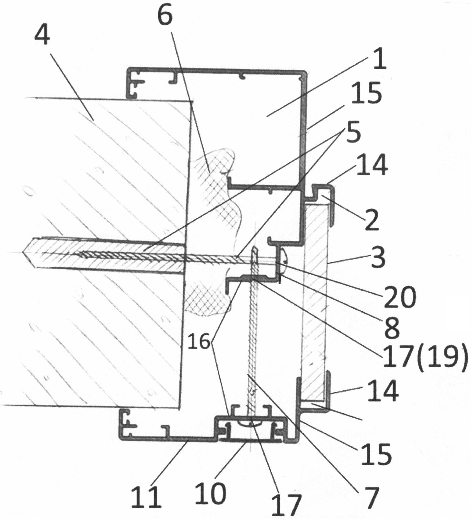
на фиг. 1 - показано крепление с использованием профилей, в которых открытые пазы для добора выполнены в крайнем положении в сторону середины проема и направлены навстречу друг другу;in FIG. 1 shows a fastening using profiles in which open grooves for extension are made in the extreme position toward the middle of the opening and are directed towards each other;
на фиг. 2 - показано крепление с использованием профилей, и дополнительного промежуточного профиля для увеличения расстояния между профилями.in FIG. 2 shows the fastening using profiles, and an additional intermediate profile to increase the distance between the profiles.
Система профилей для изготовления коробки проема, содержит два профиля: основной 1 и дополнительный 11, связанные между собой через доборный элемент 3, установленный в открытых пазах 2 и 12, несомых профилями навстречу друг другу. Стенки 14 открытых пазов выполнены на внешних поверхностях 15 профилей со стороны середины проема, а в стенках 16 профилей, направленных друг к другу, выполнены отверстия 17 и/или канавка 19 по длине профиля для их разъемного крепления 7 и обжатия стенки 4 проема параллельно доборному элементу 3. При этом, по меньшей мере, в одном профиле 1 параллельно доборному элементу выполнен уступ 8 с отверстиями 20 для разъемного крепежа 5 к стенке 4 проема в направлении перпендикулярном доборному элементу 3.The system of profiles for the manufacture of the opening box contains two profiles: the main 1 and the additional 11, interconnected via an
Между профилями 1 и 11 на стенке 4 проема закреплен промежуточный профиль 13 для разъемного крепления 7 к нему другого профиля 11 и обжатия стенки 4 проема параллельно доборному элементу 3.Between the
При осуществлении фиксации коробки предварительно выполняют в дополнительном профиле 11 дополнительный элемент 7 разъемного крепежа для регулировки расстояния между этими профилями, при установке элементов добора 3 размещают их концы в открытых пазах 2 и 12 основного 1 и дополнительного 11 профилей, а фиксацию коробки осуществляют, используя этот дополнительный элемент 7 разъемного крепежа, регулируя расстояние между этими профилям и, соответственно, обжатие стенки 4 проема. Это позволяет обеспечить регулировку прочности крепления и обжатия стенки проема для оперативного устранения недостатков монтажа и компенсации неровностей стен проема, позволяет исключить нарушение целостности и разрушение хрупкого добора, например, кафельной плитки, и возможность разборки и повторной установки коробки без искажения геометрии профиля. Для обеспечения достижения указанных выше преимуществ в готовых проемах с увеличенной толщиной стен перед установкой элементов добора 3 на стенке проема между основным и дополнительным профилями закрепляют промежуточный профиль 13 для регулировки расстояния между основным 1 и дополнительным 11 профилями, а дополнительный элемент 7 разъемного крепежа фиксируют на промежуточном профиле 13.When carrying out the fixing of the box, an
Предлагаемая система профилей предназначена для универсального применения доборных элементов в виде любых видов плит (ЛГК, ДВП, ЛДСП, ГВЛ, сендвич-панель, и т.д.), возможности установки уплотнителя по периметру дверного короба и дополнительного профиля, возможность крепления (механического) саморезами к стене, без применения дополнительных элементов (подвесов). Соединение профилей короба в одной плоскости осуществляется с применением сухарей, для обеспечения жесткости и беззазорного углового соединения, при угле запила профилей короба под 45 градусов, расположенных в угловых участках дверного профиля короба, как с применением клея, так и без него, что делает возможным разборку дверной коробки и повторный монтаж, без деформирования деталей дверного короба.The proposed system of profiles is designed for the universal use of additional elements in the form of any types of plates (LGK, DVP, LDSP, GVL, a sandwich panel, etc.), the possibility of installing a seal around the perimeter of the door frame and an additional profile, the possibility of fastening (mechanical) screws to the wall, without the use of additional elements (suspensions). The connection of the duct profiles in one plane is carried out using crackers to ensure rigidity and clearance-free angular connection, at an angle washed down the duct profiles at 45 degrees located in the corner sections of the duct door profile, both with or without glue, which makes it possible to disassemble door frame and reassembly, without deformation of door frame parts.
Уступ 8 обеспечивает удобство крепления с последующей укладкой плитки (7-9 мм) с заходом ее в паз 2, например, на дополнительную опору 9, что позволяет улучшить эстетику, исключая этим дальнейшие механические разрывы (трещины) между коробом и добором (кафельной настенной плиткой).The
Крепление дверного короба с применением дополнительного профиля 11 (фиг. 1, 4) обеспечивает возможность использования скрытого крепления 7 с декоративной маскировкой 10 (нащельник, крышка, накладка) и обеспечить обжатие стены с целью скрытия неровностей (путем механического крепления саморезами, со сверлом длинной в зависимости от толщены стены). Основной профиль дверного короба имеет центровочную канавку 19 (фиг. 4) (по всему периметру дверной коробки) для ориентировки сверла самореза. Механический монтаж основного и дополнительного профилей дверного короба и осуществляется одновременно с креплением доборных элементов в пазах профилей, с клеем или без него.Fastening the door frame using an additional profile 11 (Figs. 1, 4) makes it possible to use the
Монтаж профилей дверной коробки (фиг. 2) на стенах с большой толщиной осуществляется, например, через прикрепленный в проеме стены брус (40×40 мм) или металлический профиль типа КНАУФ, саморезами или дюбель-гвоздями.The installation of door frame profiles (Fig. 2) on walls with large thickness is carried out, for example, through a beam (40 × 40 mm) attached to the wall opening or a metal profile of the KNAUF type, with self-tapping screws or dowels-nails.
Таким образом, при использовании заявленной полезной модели достигается технический результат, которым является обеспечение надежного крепления коробки в готовых проемах с различной, в том числе, увеличенной толщиной стен с исключением нарушения целостности и разрушения добора, возможности разборки и повторной установки коробки и обеспечения регулировки прочности крепления и обжатия стенки проема для оперативного устранения недостатков монтажа и компенсации неровностей стен проема.Thus, when using the claimed utility model, a technical result is achieved, which is to ensure reliable fastening of the box in the finished openings with various, including increased wall thicknesses, with the exception of violation of the integrity and destruction of the extension, the possibility of disassembling and reinstalling the box and ensuring adjustment of the fastening strength and compression of the wall of the opening to quickly eliminate the shortcomings of the installation and compensation of irregularities of the walls of the opening.
Claims (3)
Priority Applications (1)
| Application Number | Priority Date | Filing Date | Title |
|---|---|---|---|
| RU2015116329/12U RU158137U1 (en) | 2015-04-29 | 2015-04-29 | SYSTEM OF PROFILES FOR MANUFACTURE OF THE DOOR OPENING BOX |
Applications Claiming Priority (1)
| Application Number | Priority Date | Filing Date | Title |
|---|---|---|---|
| RU2015116329/12U RU158137U1 (en) | 2015-04-29 | 2015-04-29 | SYSTEM OF PROFILES FOR MANUFACTURE OF THE DOOR OPENING BOX |
Publications (1)
| Publication Number | Publication Date |
|---|---|
| RU158137U1 true RU158137U1 (en) | 2015-12-20 |
Family
ID=54871794
Family Applications (1)
| Application Number | Title | Priority Date | Filing Date |
|---|---|---|---|
| RU2015116329/12U RU158137U1 (en) | 2015-04-29 | 2015-04-29 | SYSTEM OF PROFILES FOR MANUFACTURE OF THE DOOR OPENING BOX |
Country Status (1)
| Country | Link |
|---|---|
| RU (1) | RU158137U1 (en) |
Cited By (1)
| Publication number | Priority date | Publication date | Assignee | Title |
|---|---|---|---|---|
| RU194621U1 (en) * | 2019-10-08 | 2019-12-17 | Общество с ограниченной ответственностью "Аргус-Волга" | PVC DOOR BOX PROFILE |
-
2015
- 2015-04-29 RU RU2015116329/12U patent/RU158137U1/en active IP Right Revival
Cited By (1)
| Publication number | Priority date | Publication date | Assignee | Title |
|---|---|---|---|---|
| RU194621U1 (en) * | 2019-10-08 | 2019-12-17 | Общество с ограниченной ответственностью "Аргус-Волга" | PVC DOOR BOX PROFILE |
Similar Documents
| Publication | Publication Date | Title |
|---|---|---|
| US8650818B1 (en) | Mounting apparatus for door jambs and window frames | |
| RU2599243C1 (en) | System of construction translucent walling structures | |
| RU158137U1 (en) | SYSTEM OF PROFILES FOR MANUFACTURE OF THE DOOR OPENING BOX | |
| RU134207U1 (en) | SYSTEM OF PROFILES FOR MANUFACTURE OF THE DOOR OPENING BOX | |
| JP6148616B2 (en) | curtain wall | |
| JP5118535B2 (en) | Partially refurbished door frame and its refurbishing method | |
| RU2599700C1 (en) | Method for mounting door frame to the opening wall and system of profiles to produce door opening frame | |
| RU98213U1 (en) | WINDOW BLOCK | |
| JP6512870B2 (en) | Door frame refurbished structure and refurbished door | |
| JPH0616101Y2 (en) | Blind built-in obstruction unit | |
| RU2343263C2 (en) | System of decorative profiles of windows and doorways openings | |
| RU142648U1 (en) | ALUMINUM BOX INVISIBLE | |
| RU132120U1 (en) | STEEL DOOR | |
| JP2008133693A (en) | Partly covering remodeled door frame | |
| KR20170056871A (en) | Fire door reinforced intensity | |
| JP6127110B2 (en) | Rail member repair method | |
| JP2020176440A (en) | Window part connecting structure | |
| RU66395U1 (en) | SYSTEM OF FINISHING PROFILES OF WINDOWS AND DOORS | |
| JP7306944B2 (en) | Fittings | |
| JP2018131903A (en) | Door frame renovation structure and renovated door | |
| EP1643069A2 (en) | A frame for windows, french windows and the like | |
| RU108077U1 (en) | WINDOW AND DOOR FINISHING SYSTEM | |
| JP2022067377A (en) | Renovation sash | |
| JP7088735B2 (en) | Refurbished fittings | |
| TWI671464B (en) | Window frame renovating structure |
Legal Events
| Date | Code | Title | Description |
|---|---|---|---|
| MM1K | Utility model has become invalid (non-payment of fees) |
Effective date: 20160430 |
|
| NF1K | Reinstatement of utility model |
Effective date: 20170911 |