RU135740U1 - VERTICAL CENTRIFUGAL PUMP INSTALLATION - Google Patents
VERTICAL CENTRIFUGAL PUMP INSTALLATION Download PDFInfo
- Publication number
- RU135740U1 RU135740U1 RU2013130964/03U RU2013130964U RU135740U1 RU 135740 U1 RU135740 U1 RU 135740U1 RU 2013130964/03 U RU2013130964/03 U RU 2013130964/03U RU 2013130964 U RU2013130964 U RU 2013130964U RU 135740 U1 RU135740 U1 RU 135740U1
- Authority
- RU
- Russia
- Prior art keywords
- pump
- spacer
- electric motor
- column
- installation
- Prior art date
Links
Images

Landscapes
- Structures Of Non-Positive Displacement Pumps (AREA)
Abstract
1. Вертикальная центробежная насосная установка, содержащая электродвигатель, погружной центробежный насос, коаксиально установленный в колонне и закрепленный в основании, имеющем входной и выходной каналы, проставку с верхним и нижним фланцами, в которой размещен узел соединения валов электродвигателя и насоса, и отвод для воздуха, отличающаяся тем, что валы электродвигателя и насоса соединены посредством магнитной муфты, в верхней части колонны дополнительно установлен магнитный сепаратор, а корпус насоса вкручен в основание.2. Установка по п.1, отличающаяся тем, что верхний фланец проставки снабжен упорами для регулирования положения электродвигателя относительно оси насоса, а в нижнем фланце проставки отвод для воздуха выполнен в виде радиального канала.1. A vertical centrifugal pump installation comprising an electric motor, a submersible centrifugal pump, coaxially mounted in a column and fixed in a base having inlet and outlet channels, a spacer with upper and lower flanges, in which a connection unit of the motor and pump shafts is located, and an air outlet characterized in that the shafts of the electric motor and pump are connected by means of a magnetic coupling, an additional magnetic separator is installed in the upper part of the column, and the pump housing is screwed into the base. 2. Installation according to claim 1, characterized in that the upper flange of the spacer is provided with stops for adjusting the position of the electric motor relative to the axis of the pump, and in the lower flange of the spacer the air outlet is made in the form of a radial channel.
Description
Предлагаемая полезная модель относится к области насосных установок, предназначенных для нагнетания под высоким давлением жидкости, которая может использоваться для различных нужд потребителя, например, для поддержания пластового давления (ППД).The proposed utility model relates to the field of pumping plants designed for injection under high pressure fluid, which can be used for various consumer needs, for example, to maintain reservoir pressure (RPM).
Из существующего уровня техники известна горизонтальная дожимная насосная установка (патент №2380577 РФ, МПК F04D 13/06, F04D 9/04, 2010), содержащая опорную раму, электродвигатель, расположенные на одном валу вспомогательный и основной центробежные насосы, узел нагнетания и узлы всасывания на входе в каждый насос, при этом вспомогательный насос соединен с электродвигателем, узел нагнетания вспомогательного насоса совмещен с узлом всасывания основного насоса, а производительность основного насоса значительно превышает вспомогательного.A horizontal booster pumping unit (RF patent No. 2380577, IPC F04D 13/06, F04D 9/04, 2010) is known in the prior art, comprising a support frame, an electric motor, auxiliary and main centrifugal pumps, a discharge unit and suction units located on the same shaft. at the entrance to each pump, while the auxiliary pump is connected to the electric motor, the discharge unit of the auxiliary pump is combined with the suction unit of the main pump, and the capacity of the main pump is significantly higher than the auxiliary.
Недостатками данной конструкции являются значительные габаритные размеры установки по длине и высокая металлоемкость рамы.The disadvantages of this design are the significant overall dimensions of the installation along the length and high metal consumption of the frame.
Наиболее близкой по технической сущности к предлагаемой установке является вертикальная центробежная насосная установка, содержащая электродвигатель, зажатый между двумя фланцами насос, размещенный внутри колонны и прикрепленный к ее основанию, имеющему входной и выходной каналы, отвод для выхода воздуха в крышке колонны, узел соединения валов электродвигателя и насоса, расположенный внутри конической проставки, нижний фланец которой состыкован с крышкой колонны, а на верхнем фланце установлен электродвигатель (EP 0907029 A2, F04D 29/40, 1998). Валы электродвигателя и насоса соединены с помощью разъемной муфты, крепление насоса к основанию осуществляется с помощью болта, вкрученного в вал.Closest to the technical nature of the proposed installation is a vertical centrifugal pump installation, containing an electric motor, a pump sandwiched between two flanges, located inside the column and attached to its base, having inlet and outlet channels, an outlet for air outlet in the column cover, a motor shaft connection unit and a pump located inside a conical spacer, the lower flange of which is joined to the column cover, and an electric motor is installed on the upper flange (EP 0907029 A2, F04D 29/40, 1998). The shafts of the electric motor and pump are connected using a detachable coupling, the pump is fixed to the base with a bolt screwed into the shaft.
Недостатком данной установки является ограничение давления перекачиваемой жидкости, поступающей в установку.The disadvantage of this installation is the restriction of the pressure of the pumped liquid entering the installation.
Задачей полезной модели является обеспечение работоспособности установки при высоком давлении на входе за счет повышения герметичности.The objective of the utility model is to ensure the operability of the installation at high inlet pressure by increasing the tightness.
Указанный технический результат достигается тем, что в вертикальной центробежной насосной установке, содержащей электродвигатель, центробежный насос, закрепленный в основании, имеющим входной и выходной каналы, колонну, охватывающую насос, проставку с верхним и нижним фланцами, внутри которой размещен узел соединения валов электродвигателя и насоса, и отвод для воздуха, согласно полезной модели, валы электродвигателя и насоса соединены посредством магнитной муфты, в верхней части колонны дополнительно установлен магнитный сепаратор, а корпус насоса вкручен в основание.The specified technical result is achieved by the fact that in a vertical centrifugal pump installation containing an electric motor, a centrifugal pump fixed in the base having inlet and outlet channels, a column covering the pump, a spacer with upper and lower flanges, inside of which there is an assembly for connecting the motor and pump shafts , and the air outlet, according to a utility model, the shafts of the electric motor and pump are connected by means of a magnetic coupling, a magnetic separator is additionally installed in the upper part of the column, and the pump housing is screwed into the base.
Для регулировки радиального положения электродвигателя верхний фланец проставки снабжен упорами.To adjust the radial position of the motor, the upper flange of the spacer is equipped with stops.
Кроме того, отвод для выхода воздуха может быть выполнен в виде радиального канала внутри нижнего фланца проставки.In addition, the exhaust outlet can be made in the form of a radial channel inside the lower spacer flange.
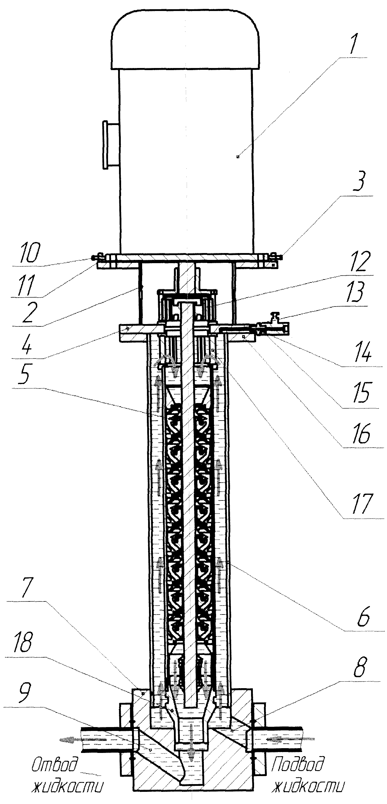
На фиг. изображен общий вид заявляемой установки в разрезе.In FIG. shows a General view of the inventive installation in the context.
Вертикальный насосная установка содержит электродвигатель 1, цилиндрическую проставку 2 с верхним 3 и нижним 4 фланцами, центробежный насос 5, коаксиально размещенный внутри колонны 6, и основание 7, имеющее входной 8 и выходной 9 каналы. Электродвигатель 1 установлен на верхний фланец 3 и выставлен соосно с центробежным насосом 5 посредством регулировочных винтов 10, установленных в упорах 11. Внутри вертикально ориентированной проставки 2 размещена магнитная муфта 12, соединяющая вал электродвигателя 1 с валом насоса 5.The vertical pump installation includes an
Магнитная муфта 12 опирается на нижний фланец 4 проставки 2, в котором имеются радиальный канал 13 для выхода воздуха, вытесняемого жидкостью, поступающей в насос 5, и штуцер 14 для подключения вентиля 15. Фланец 4 состыкован с фланцем 16, который установлен на колонне 6. За магнитной муфтой 12 в верхней части колонны 6 размещен магнитный сепаратор 17, который центрируется по насосу 5 и фланцу 4. Насос 5 закреплен в основании 7 с помощью резьбового окончания, выполненного, например, на переходнике 18. Благодаря резьбовому соединению насоса 5 с основанием 7 достигается центрирование насоса 5 в колонне 6, что обеспечивает соосность вала насоса 5 с валом электродвигателя 1 и повышает надежность и долговечность установки.The
Монтаж предлагаемой вертикальной насосной центробежной установки производят следующим образом.Installation of the proposed vertical pump centrifugal installation is as follows.
Насос 5 с присоединенным к нему переходником 18 закручивают в основание 7; затем в основание 7 герметично устанавливают колонну 6 с верхним фланцем 16. На корпусе насоса 5 монтируют магнитный сепаратор 17; после чего на фланце 16 закрепляют проставку 2 с нижним фланцем 4. Далее на вал насоса 5 устанавливают магнитную муфту 12, на верхнем фланце 3 проставки 5 размещают электродвигатель 1 и центрируют его при помощи регулировочных винтов 10. Благодаря центрированию снижается вероятность заклинивания вала насоса и повышается долговечность установки.The
Вертикальная насосная установка работает следующим образом.Vertical pumping unit operates as follows.
При включении электродвигателя 1, укрепленного на фланце 3, вращение передается на вал насоса 5 через магнитную муфту 12, защищаемую магнитным сепаратором 17 от попадания металлических включений. Перекачиваемая жидкость с давлением на входе до 20 МПа, подается по подводящему трубопроводу через входной канал 8 основания 7 в колонну 6, где поднимается по кольцевому зазору и поступает в насос 5 сверху. Воздух из колонны 6, вытесняемый поднимающейся жидкостью, по каналу 13 через штуцер 14 выводится из установки. После чего вентиль 15 переводится в закрытое положение. Поступившая в насос 5 жидкость под давлением нагнетается обратно в основание 7 и через выходной канал 9 попадает в отводящий трубопровод и поступает потребителю.When you turn on the
Таким образом, предлагаемая конструкция более технологична, так как магнитная муфта обеспечивает высокую степень герметичности насоса без использования дополнительных уплотнительных средств, что обеспечивает высокие входные давления, а также предотвращает поломку вала двигателя в случае заклинивании вала насоса.Thus, the proposed design is more technologically advanced, since the magnetic coupling provides a high degree of tightness of the pump without the use of additional sealing means, which ensures high inlet pressures and also prevents breakage of the motor shaft in case of jamming of the pump shaft.
Установка отличается простотой при сборке за счет резьбового соединения насоса с основанием, которое обеспечивают центрирование насоса в колонне.The installation is easy to assemble due to the threaded connection of the pump with the base, which provides centering of the pump in the column.
Предлагаемая установка является промышленно применимой, так как для его реализации используется стандартные конструктивные элементы.The proposed installation is industrially applicable, since standard structural elements are used for its implementation.
Claims (2)
Priority Applications (1)
| Application Number | Priority Date | Filing Date | Title |
|---|---|---|---|
| RU2013130964/03U RU135740U1 (en) | 2013-07-04 | 2013-07-04 | VERTICAL CENTRIFUGAL PUMP INSTALLATION |
Applications Claiming Priority (1)
| Application Number | Priority Date | Filing Date | Title |
|---|---|---|---|
| RU2013130964/03U RU135740U1 (en) | 2013-07-04 | 2013-07-04 | VERTICAL CENTRIFUGAL PUMP INSTALLATION |
Publications (1)
| Publication Number | Publication Date |
|---|---|
| RU135740U1 true RU135740U1 (en) | 2013-12-20 |
Family
ID=49785532
Family Applications (1)
| Application Number | Title | Priority Date | Filing Date |
|---|---|---|---|
| RU2013130964/03U RU135740U1 (en) | 2013-07-04 | 2013-07-04 | VERTICAL CENTRIFUGAL PUMP INSTALLATION |
Country Status (1)
| Country | Link |
|---|---|
| RU (1) | RU135740U1 (en) |
Cited By (3)
| Publication number | Priority date | Publication date | Assignee | Title |
|---|---|---|---|---|
| RU196494U1 (en) * | 2019-12-18 | 2020-03-03 | Сергей Викторович Яблочко | Six-section electric pump unit |
| RU196491U1 (en) * | 2019-12-18 | 2020-03-03 | Сергей Викторович Яблочко | Two-section electric pump unit |
| RU196653U1 (en) * | 2019-12-18 | 2020-03-11 | Сергей Викторович Яблочко | Three-section electric pump unit |
-
2013
- 2013-07-04 RU RU2013130964/03U patent/RU135740U1/en active
Cited By (3)
| Publication number | Priority date | Publication date | Assignee | Title |
|---|---|---|---|---|
| RU196494U1 (en) * | 2019-12-18 | 2020-03-03 | Сергей Викторович Яблочко | Six-section electric pump unit |
| RU196491U1 (en) * | 2019-12-18 | 2020-03-03 | Сергей Викторович Яблочко | Two-section electric pump unit |
| RU196653U1 (en) * | 2019-12-18 | 2020-03-11 | Сергей Викторович Яблочко | Three-section electric pump unit |
Similar Documents
| Publication | Publication Date | Title |
|---|---|---|
| RU135740U1 (en) | VERTICAL CENTRIFUGAL PUMP INSTALLATION | |
| CN203926033U (en) | The horizontal multi-stage centrifugal pump of a kind of end water sucting belt inducer | |
| CN203130527U (en) | Single-stage vertical direct-connected centrifugal pump with guide vanes | |
| EA026452B1 (en) | Centrifugal multistage electric pump | |
| CN102086889A (en) | Automatic cooling type sewage pump | |
| EP3992463A1 (en) | Multistage centrifugal pump with two parallel flows of pumped medium | |
| RU84074U1 (en) | SEALED PUMP UNIT | |
| CN106762676B (en) | A kind of centrifugal multistage pump multiple centrifugal pump delivery chamber | |
| CN108980054A (en) | Vertical high-efficiency energy-saving automatic control self-priming scale pump | |
| CN109667764B (en) | Can dismantle high-efficient pump with inhaling device | |
| KR101221056B1 (en) | The underwater pump will be able to accomplish the function of the inline pump | |
| RU153798U1 (en) | SUBMERSIBLE TYPE PUMP FOR TRANSFER OF LIQUID METALS OF NUCLEAR POWER PLANTS | |
| CN205533277U (en) | Horizontal multi -stage centrifugal pump | |
| CN201874842U (en) | Convenient disassembly type centrifugal pipeline pump | |
| RU205739U1 (en) | Centrifugal sectional pump with two parallel flows of the pumped medium | |
| RU2016114412A (en) | Multi-stage high pressure flanged pump assembly | |
| CN205478554U (en) | Horizontal single -stage double entry pump | |
| AU2012101036A4 (en) | Windows Pump | |
| CN204003508U (en) | A kind of LNG latent liquid type centrifugal pump | |
| CN203702579U (en) | Amphibious mute high-pressure pump | |
| CN220487887U (en) | Submersible electric pump for well | |
| CN204327527U (en) | General cavitation performance test run device structure | |
| RU123076U1 (en) | CENTRIFUGAL MULTI-STAGE ELECTRIC PUMP | |
| RU150035U1 (en) | HORIZONTAL PUMP INSTALLATION | |
| RU2684049C1 (en) | Installation horizontal pump |