RU135386U1 - PIPELINE SUPPORT IN CASE - Google Patents
PIPELINE SUPPORT IN CASE Download PDFInfo
- Publication number
- RU135386U1 RU135386U1 RU2013121471/06U RU2013121471U RU135386U1 RU 135386 U1 RU135386 U1 RU 135386U1 RU 2013121471/06 U RU2013121471/06 U RU 2013121471/06U RU 2013121471 U RU2013121471 U RU 2013121471U RU 135386 U1 RU135386 U1 RU 135386U1
- Authority
- RU
- Russia
- Prior art keywords
- clamps
- pipeline
- support
- pipe
- legs
- Prior art date
Links
Images


Landscapes
- Supports For Pipes And Cables (AREA)
Abstract
Опора трубопровода в футляре, содержащая превышающий диаметр трубопровода хомут из двух полухомутов, нижний из которых снабжен, как минимум, двумя ножками, стягивающие полухомуты болтовые соединения, пластину между трубой и хомутом и ребра жесткости, взаимодействующие с полухомутами и ножками, отличающаяся тем, что в опору дополнительно введены ребра жесткости, взаимодействующие с болтовыми соединениями, а пластина состоит, как минимум, из двух частей, каждая из которых жестко закреплена на внутренней поверхности соответствующего полухомута и выполнена из фрикционно-диэлектрического материала, при этом ребра жесткости, взаимодействующие с болтовыми соединениями, расположены с обеспечением исключения вращения головки болта.A pipe support in a case containing a pipe clamp exceeding the diameter of two half-clamps, the lower of which is equipped with at least two legs, bolt-tightening half-clamps, a plate between the pipe and clamp and stiffeners interacting with half-clamps and legs, characterized in that stiffening ribs interacting with bolted joints are additionally introduced into the support, and the plate consists of at least two parts, each of which is rigidly fixed to the inner surface of the corresponding floor slough and made of friction-dielectric material, wherein the ribs cooperating with bolted joints are arranged to ensure exclusion of rotation of the bolt head.
Description
Полезная модель относится к области прокладки технологических и магистральных трубопроводов, предназначена для их протаскивания внутри защитного футляра/кожуха или внутри другой трубы и может быть использована в качестве опоры, в частности, при строительстве переходов, прокладываемых под автомобильными и железными дорогами, по дну водоемов или в стесненных условиях, например, под существующими насыпями, а также другими инженерными сооружениями.The utility model relates to the field of laying technological and trunk pipelines, is designed to be dragged inside a protective case / casing or inside another pipe and can be used as a support, in particular, in the construction of passages laid under roads and railways, along the bottom of water bodies or in cramped conditions, for example, under existing embankments, as well as other engineering structures.
Известно опорно-направляющее кольцо (ОНК) на переходе трубопровода в защитном кожухе, включающее не менее двух кольцевых сегментов, выполненных цельными с защитными выступами из диэлектрического материала и стянутых между собой болтовыми соединениями. А между кольцевыми сегментами и трубопроводом установлена защитно-корректирующая прокладка (патент РФ на полезную модель №62192, МПК F16L 1/028, F16L 7/00. Опубл. 27.03.2007 г.).It is known support ring (ONK) at the transition of the pipeline in a protective casing, comprising at least two ring segments made integral with protective protrusions of dielectric material and tightened together by bolted connections. And between the ring segments and the pipeline a protective corrective gasket is installed (RF patent for utility model No. 62192, IPC F16L 1/028,
К недостаткам известного опорно-направляющего кольца относится усложненность монтажа кольцевых сегментов на защитно-корректирующую прокладку из-за отсутствия ее закрепления на трубопроводе. Кроме того, защитно-корректирующая прокладка, не являясь фрикционной, не исключает перемещения опоры по трубопроводу, что недопустимо, т.к. опоры должны располагаться на трубопроводе на расчетном фиксированном расстоянии. Не исключено и самопроизвольное раскручивание гайки болтового соединения при вибрациях трубопровода.The disadvantages of the known support-guide ring include the complexity of mounting the annular segments on the protective-corrective gasket due to the lack of its fastening on the pipeline. In addition, the protective and corrective gasket, while not friction, does not exclude the movement of the support through the pipeline, which is unacceptable, because supports should be located on the pipeline at a calculated fixed distance. It is also possible that spontaneous unscrewing of the nut of the bolted joint during vibration of the pipeline.
Известно также опорно-направляющее кольцо для трубопровода, содержащее последовательно соединенные между собой дуги в количестве, не менее двух, выполненные из металлических полос и расположенные по окружности, диаметр которой превышает диаметр трубы трубопровода в месте расположения опорно-направляющего кольца. Причем дуги выполнены с разъемными соединениями в виде отогнутых уголков, снабженных ребрами жесткости - двумя или более - и скрепленных болтовыми соединениями, и каждая дуга снабжена закрепленным на нем опорным элементом - одним или более в виде приваренного металлического колодца с соответствующим вкладышем, выполненным из полиэтилена низкой плотности методом литья в пресс-форме и соединенным со стенками колодца запрессовкой с обеспечением фиксатора в виде продольного выступа на стенке колодца, совмещенного с соответствующей впадиной на стенке вкладыша. А вкладыш в поперечном сечении выполнен с внутренними полостями, открытыми со стороны плоскости дуги, и оси которых взаимоперпендикулярны с продольной осью трубопровода (патент РФ на полезную модель №122462, МПК F16L 7/02. Опубл. 27.11.2012 г.).A support ring for a pipeline is also known, comprising arcs connected in series with each other in an amount of at least two, made of metal strips and arranged in a circle whose diameter exceeds the diameter of the pipe at the location of the support ring. Moreover, the arcs are made with detachable joints in the form of bent corners, equipped with stiffeners - two or more - and fastened by bolt connections, and each arc is equipped with a supporting element fixed to it - one or more in the form of a welded metal well with a corresponding insert made of low polyethylene density by injection molding and connected to the walls of the well by pressing to provide a latch in the form of a longitudinal protrusion on the wall of the well, combined with the corresponding depressions first on the liner wall. A liner in cross section is made with internal cavities open from the side of the arc plane, and the axes of which are mutually perpendicular to the longitudinal axis of the pipeline (RF patent for utility model No. 122462, IPC F16L 7/02. Publ. 11/27/2012).
Однако, установка опорно-направляющего кольца непосредственно на трубопровод может привести к нарушению антикоррозийного покрытия трубопровода. Помимо этого, не исключено самопроизвольное раскручивание гайки болтового соединения при вибрациях трубопровода.However, installing the support ring directly on the pipeline can lead to a violation of the corrosion-resistant coating on the pipeline. In addition, spontaneous unscrewing of the nut of the bolted connection during vibration of the pipeline is not ruled out.
Наиболее близкой к предлагаемой по своей технической сущности является опора трубопровода в футляре, содержащая превышающий диаметр трубопровода хомут из двух полухомутов, нижний из которых снабжен, как минимум, двумя ножками, стягивающие полухомуты болтовые соединения, пластину между трубой и хомутом и ребра жесткости, взаимодействующие с полухомутами и ножками. При этом пластина прижата к трубопроводу полухомутами через элементы из пиломатериалов (Типовые строительные конструкции, изделия и узлы. Серия 5.905.-25.05. «Оборудование, узлы, детали наружных и внутренних газопроводов». Выпуск 1, часть 2 «Оборудование, узлы, детали. Рабочие чертежи», УГ 15.00. Введены в действие ОАО СПКБ «Газпроект»-БТЦ приказом №81 от 07 ноября 2005 года).Closest to the proposed technical essence is a pipe support in a case containing a pipe clamp exceeding the diameter of the pipe from two half clamps, the lower of which is equipped with at least two legs, bolt joints that tighten the half clamps, a plate between the pipe and the clamp and stiffeners interacting with half clamps and legs. In this case, the plate is pressed to the pipeline in half-clamps through elements of lumber (Typical building structures, products and units. Series 5.905.-25.05. “Equipment, units, parts of external and internal gas pipelines.”
Но в этой опоре имеющиеся элементы из пиломатериалов уменьшают срок ее службы и надежность. Кроме того, из-за низкого коэффициента трения между элементами из пиломатериалов и металлом полухомутов не исключен сход полухомутов с прокладки при протягивании трубопровода в футляре, что снижает надежность опоры. При этом усложнен монтаж полухомутов на элементы из пиломатериалов и пластину из-за отсутствия их закрепления, и не исключено самопроизвольное раскручивания гайки болтового соединения при вибрациях трубопровода.But in this support, the available elements from lumber reduce its service life and reliability. In addition, due to the low coefficient of friction between the elements from lumber and the metal of the half-clamps, it is possible that the half-clamps come off the gasket when pulling the pipeline in the case, which reduces the reliability of the support. At the same time, the installation of half-clamps on the elements of lumber and the plate is complicated due to the lack of their fastening, and spontaneous unscrewing of the bolt nut during vibration of the pipeline is not ruled out.
Задачей, на решение которой направлена заявленная полезная модель, является увеличение надежности опоры, упрощение ее монтажа.The task to which the claimed utility model is directed is to increase the reliability of the support and simplify its installation.
Технический результат заключается в повышении надежности эксплуатации трубопровода.The technical result is to increase the reliability of the operation of the pipeline.
Поставленная задача решается тем, что в опору трубопровода в футляре, содержащую превышающий диаметр трубопровода хомут из двух полухомутов, нижний из которых снабжен, как минимум, двумя ножками, стягивающие полухомуты болтовые соединения, пластину между трубой и хомутом и ребра жесткости, взаимодействующие с полухомутами и ножками, дополнительно введены ребра жесткости, взаимодействующие с болтовыми соединениями, а пластина состоит, как минимум, из двух частей, каждая из которых жестко закреплена на внутренней поверхности соответствующего полухомута и выполнена из фрикционно-диэлектрического материала. При этом ребра жесткости, взаимодействующие с болтовыми соединениями, расположены с обеспечением исключения вращения головки болта.The problem is solved in that in the pipe support in a case containing a pipe clamp exceeding the diameter of the pipe clamp of two half-clamps, the lower of which is equipped with at least two legs, bolt-tightening half-clamps, a plate between the pipe and the clamp and stiffeners interacting with the half-clamps and legs, additionally introduced stiffeners interacting with bolted joints, and the plate consists of at least two parts, each of which is rigidly fixed to the inner surface poluhomuta present and is made of friction-dielectric material. In this case, stiffening ribs interacting with bolted joints are located with the exception of rotation of the bolt head.
Разделение пластины, как минимум, на две части, каждая из которых жестко закреплена на внутренней поверхности соответствующего полухомута, упрощает монтаж полухомутов опоры на трубопроводе.Dividing the plate into at least two parts, each of which is rigidly fixed to the inner surface of the corresponding half-clamp, simplifies the installation of half-clamps of the support on the pipeline.
Выполнение частей пластины из фрикционно-диэлектрического материала повышает коэффициент трения между полухомутом и трубопроводом, что исключает перемещение опоры по трубопроводу при его протягивании в футляре и тем самым повышает ее надежность. Одновременно пластина из фрикционно-диэлектрического материала электроизолирует трубопровод от влияния источников блуждающих токов, предотвращая электрокоррозию трубопровода.The implementation of the parts of the plate of friction-dielectric material increases the coefficient of friction between the half-clamp and the pipeline, which eliminates the movement of the support through the pipeline when it is pulled in the case and thereby increases its reliability. At the same time, a plate of friction-dielectric material electrically insulates the pipeline from the influence of stray current sources, preventing electrocorrosion of the pipeline.
Расположение введенных ребер жесткости, взаимодействующих с болтовыми соединениями, с обеспечением исключения вращения головки болта упрощает монтаж полухомутов опоры на трубопроводе.The location of the introduced stiffeners interacting with bolted joints, ensuring the exclusion of rotation of the bolt head, simplifies the installation of support half clamps on the pipeline.
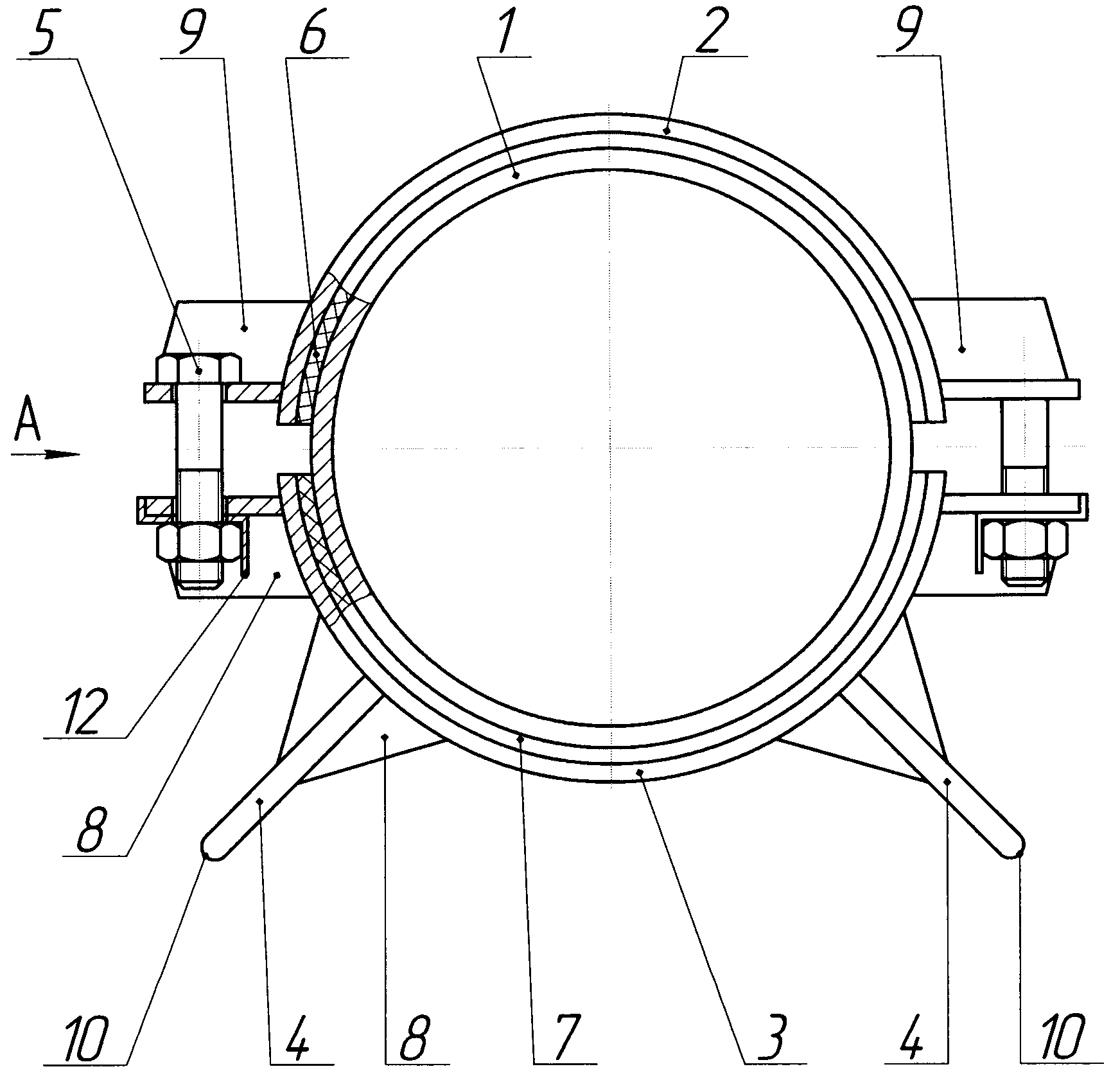
На фиг.1 изображена опора трубопровода с металлическими ножками, общий вид; на фиг.2 изображена опора трубопровода с опорной частью ножек из антифрикционно-диэлектрического материала, общий вид; на фиг.3 - вид А фиг.1, 2.Figure 1 shows the support of the pipeline with metal legs, General view; figure 2 shows the support of the pipeline with the supporting part of the legs of the antifriction dielectric material, General view; figure 3 is a view And figure 1, 2.
Опора трубопровода 1 содержит (фиг.1, 2) превышающий диаметр трубопровода 1 хомут из двух полухомутов 2 и 3, нижний 3 из которых снабжен двумя ножками 4, стягивающие полухомуты 2 и 3 болтовые соединения 5, пластину из двух частей 6 и 7, ребра жесткости 8, взаимодействующие с полухомутами 2, 3 и ножками 4. Ребра жесткости 9, взаимодействующие с болтовыми соединениями 5, расположены с обеспечением исключения вращения головки болта болтовых соединений 5.The support of the
В опоре трубопровода 1 пластина может быть выполнена, например, из паронита, полухомуты 2, 3 и ножки 4 - металлические; опорная часть 10 ножки 4 - металлическая (фиг.1) или из антифрикционно-диэлектрического материала (фиг.2), например, Susta РЕЕК и т.п. Опорная часть 10 из антифрикционно-диэлектрического материала, электроизолирующая опору от влияния источников блуждающих токов, закрепляется на металлической ножке 4 с помощью, например, запрессовки или установки на клей, или разъемного соединения 11. Торцы пластины совпадают или выступают за торцы полухомутов 2 и 3. С целью исключения саморазвинчивания гайки болтового соединения 5 при вибрации трубопровода 1 используется стопорный элемент 12.In the support of the
При необходимости верхний полухомут 2 может быть снабжен ножкой (не показана), исключающей соприкосновение наружного антикоррозийного покрытия трубопровода 1 с внутренней поверхностью футляра, что исключает нарушение наружного антикоррозийного покрытия трубопровода 1.If necessary, the
Опора трубопровода в футляре работает следующим образом.The support pipe in the case works as follows.
Под трубопровод 1 подводят полухомут 3, снабженный двумя ножками 4, с жестко закрепленной на его внутренней поверхности фрикционно-диэлектрической пластиной 7. Затем на трубопровод 1 оппозиционно полухомуту 3 накладывают полухомут 2 с жестко закрепленной на нем фрикционно-диэлектрической пластиной 6. При этом фрикционно-диэлектрические пластины 6 и 7 должны совпадать с торцами полухомутов 2 и 3 или выступать за них (фиг.3).A half-
Вставляют головку болтового соединения 5 в пространство между ребрами жесткости 9, взаимодействующими с болтовым соединением 5 (фиг.3). А под гайкой болтового соединения 5 помещают стопорный элемент 12.Insert the head of the
Стягивают полухомуты 2 и 3 болтовым соединением 5 необходимым усилием затяжки и фиксируют гайку болтового соединения 5 стопорным элементом 12. Затем располагают на трубопроводе 1 на расчетном расстоянии необходимое количество опор.The half-
После чего трубопровод 1 протаскивают через футляр с помощью лебедок, талей и других механизмов.Then the
Заявленная опора трубопровода в футляре повышает надежность эксплуатации трубопровода и может быть использована в диапазоне температуры окружающей среды от -60° до +40°C.The claimed support of the pipeline in the case increases the reliability of the pipeline and can be used in the range of ambient temperature from -60 ° to + 40 ° C.
Claims (1)
Priority Applications (1)
| Application Number | Priority Date | Filing Date | Title |
|---|---|---|---|
| RU2013121471/06U RU135386U1 (en) | 2013-05-07 | 2013-05-07 | PIPELINE SUPPORT IN CASE |
Applications Claiming Priority (1)
| Application Number | Priority Date | Filing Date | Title |
|---|---|---|---|
| RU2013121471/06U RU135386U1 (en) | 2013-05-07 | 2013-05-07 | PIPELINE SUPPORT IN CASE |
Publications (1)
| Publication Number | Publication Date |
|---|---|
| RU135386U1 true RU135386U1 (en) | 2013-12-10 |
Family
ID=49682333
Family Applications (1)
| Application Number | Title | Priority Date | Filing Date |
|---|---|---|---|
| RU2013121471/06U RU135386U1 (en) | 2013-05-07 | 2013-05-07 | PIPELINE SUPPORT IN CASE |
Country Status (1)
| Country | Link |
|---|---|
| RU (1) | RU135386U1 (en) |
Cited By (1)
| Publication number | Priority date | Publication date | Assignee | Title |
|---|---|---|---|---|
| RU2682278C1 (en) * | 2018-04-28 | 2019-03-18 | Ир Бон Сон | Culvert pipeline system |
-
2013
- 2013-05-07 RU RU2013121471/06U patent/RU135386U1/en active
Cited By (1)
| Publication number | Priority date | Publication date | Assignee | Title |
|---|---|---|---|---|
| RU2682278C1 (en) * | 2018-04-28 | 2019-03-18 | Ир Бон Сон | Culvert pipeline system |
Similar Documents
| Publication | Publication Date | Title |
|---|---|---|
| JP5993071B2 (en) | Assembly providing a sealing system for the opening | |
| CN108035771B (en) | A kind of not damaged quick-mount system of rail traffic shield tunnel | |
| US20150144747A1 (en) | Attachment plate and system for pipe-support interface | |
| KR101613466B1 (en) | Concrete pipe structural repair reinforcement construction method and structure constructed by the same | |
| RU135386U1 (en) | PIPELINE SUPPORT IN CASE | |
| CN207062988U (en) | A kind of pipe gallery | |
| CN109137965A (en) | A kind of pipe gallery | |
| CN103836268A (en) | Construction method for mounting waterproof sleeve of external concrete wall of basement | |
| KR101226849B1 (en) | Apparatus for connecting shaped tubes of manhole pipeline | |
| CN206861249U (en) | A kind of enamelled pressed steel biogas storage device | |
| RU83117U1 (en) | FLANGE CONNECTION | |
| CN205617425U (en) | Prefabricated structure of assembling of utility tunnel | |
| JP7179467B2 (en) | Electrical insulating plate and piping fixture using the same | |
| CN215165807U (en) | Assembled corrugated steel pipe gallery and concrete pipe gallery node structure | |
| CN211624424U (en) | Long defeated natural gas line mounting structure | |
| CN211257228U (en) | Novel assembled inspection shaft | |
| JP6456664B2 (en) | Valve body removal device | |
| CN203932939U (en) | Two cable pipe plugging parts | |
| CN216007188U (en) | Drainage pipe connecting part box structure for municipal works | |
| CN203963270U (en) | Wall-passing pipe waterproof framework | |
| CN208951509U (en) | A kind of exhaust pipe with expansion joint | |
| CN201748072U (en) | Novel insulating flange pipe fitting | |
| RU31427U1 (en) | Support ring for piping | |
| JP2016099003A (en) | Cutoff retainer for buried pipe or cable pipe comprising electric corrosion prevention means | |
| KR101853953B1 (en) | Installation structure of exhaust gas expulsion pipe and installation method thereof |