RU134814U1 - DEVICE FOR AUTOMATIC CONTROL OF EVAPORATOR - Google Patents
DEVICE FOR AUTOMATIC CONTROL OF EVAPORATOR Download PDFInfo
- Publication number
- RU134814U1 RU134814U1 RU2013127974/05U RU2013127974U RU134814U1 RU 134814 U1 RU134814 U1 RU 134814U1 RU 2013127974/05 U RU2013127974/05 U RU 2013127974/05U RU 2013127974 U RU2013127974 U RU 2013127974U RU 134814 U1 RU134814 U1 RU 134814U1
- Authority
- RU
- Russia
- Prior art keywords
- steam
- regulator
- evaporator
- solution
- actuator
- Prior art date
Links
Images

Abstract
Устройство для автоматического управления процессом выпаривания в выпарной установке, содержащее выпарной аппарат, теплообменник, уровнемер упаренного раствора, исполнительный механизм регулятора уровня упаренного раствора, вычислительное устройство, первичный преобразователь концентрации упаренного раствора, связанный с корректирующим регулятором, соединенным с регулятором соотношения "расход исходного раствора - расход тепла", который связан с исполнительным механизмом подачи пара и с расходомером исходного раствора, отличающееся тем, что устройство автоматического управления выпарной установкой снабжено связанными с входами вычислительного устройства первичными преобразователями температуры пара, давления пара и установленным после теплообменника расходомером конденсата греющего пара, при этом выход вычислительного устройства связан с регулятором соотношения "расход исходного раствора - расход тепла", и исполнительный механизм регулятора уровня упаренного раствора присоединен к входу исходного раствора, а исполнительный механизм подачи пара установлен после первичных преобразователей температуры и давления греющего пара.A device for automatically controlling the evaporation process in an evaporation plant, comprising an evaporator, a heat exchanger, an evaporated solution level gauge, an actuator for an evaporated solution level regulator, a computing device, a primary evaporated solution concentration transducer associated with a correction regulator connected to the regulator of the ratio heat consumption ", which is associated with the actuator of the steam supply and with the flow meter of the initial solution, distinguishing the automatic control device of the evaporator is equipped with primary converters of steam temperature, steam pressure and a steam flow condensate flow meter installed after the heat exchanger, the output of the computing device being connected to the regulator of the ratio of the flow rate of the initial solution to the flow rate, and the actuator of the evaporated solution level regulator is connected to the input of the initial solution, and the actuator of the steam supply set He after primary converters of temperature and pressure of the heating steam.
Description
Полезная модель относится к технике автоматического управления процессом выпаривания и может быть использовано в химической, строительной, бумажной, пищевой, радиохимической отраслях промышленности, а также в цветной металлургии при упаривании алюминатных щелоков.The utility model relates to techniques for automatically controlling the evaporation process and can be used in the chemical, construction, paper, food, radiochemical industries, as well as in non-ferrous metallurgy during the evaporation of aluminate liquors.
Известно устройство для автоматического регулирования процесса выпаривания, предназначенного для осуществления способа автоматического регулирования процесса выпаривания по авт. свид. СССР №281408, кл. B01D 1/14, G05D 11/06, 1983. Устройство содержит выпарной аппарат, регулятор уровня упаренного раствора (в аналоге - регулятор расхода сырья по уровню), корректирующий регулятор (в аналоге - регулятор расхода продукта по его плотности), первичный преобразователь концентрации упаренного раствора (в аналоге - датчик плотности), регулятор соотношения, расходомер исходного раствора (в аналоге - датчик расхода сырья) и расходомер пара (в аналоге - датчик расхода тепла (пара)).A device for automatically controlling the evaporation process, designed to implement a method for automatically controlling the evaporation process according to ed. testimonial. USSR No. 281408, class B01D 1/14, G05D 11/06, 1983. The device contains an evaporator, an evaporator solution level regulator (in the analogue, a raw material consumption regulator by level), a correction regulator (in an analogue, a product consumption regulator by its density), a primary evaporator concentration converter a solution (in the analogue - a density sensor), a ratio regulator, a flow meter of the initial solution (in an analogue - a sensor for the flow of raw materials) and a steam meter (in an analogue - a sensor for heat consumption (steam)).
Недостатком известного устройства является неустойчивость работы системы регулирования соотношения «пар-жидкость». Причиной является наличие в устройстве расходомера пара.A disadvantage of the known device is the instability of the control system of the ratio "vapor-liquid". The reason is the presence of a steam flow meter in the device.
Показания расходомеров пара и газообразных сред при отклонениях параметров измеряемой среды от их значений, принятых при расчете и градуировке, отличаются от действительных значений (Емельянов А.И. и др. «Практические расчеты в автоматике. Изд. «Машиностроение», Москва 1967 г., стр.179-181).The readings of steam and gaseous media with deviations of the parameters of the medium being measured from their values adopted in the calculation and calibration differ from the actual values (Emelyanov A.I. et al. "Practical calculations in automation. Publishing House" Engineering ", Moscow 1967. pg. 179-181).
Для расходомеров пара таким параметром является плотность пара, значение которой зависит от давления и температуры пара. И, как правило, эти параметры пара в реальных эксплуатационных условиях изменяются в существенном диапазоне.For steam flow meters, this parameter is the vapor density, the value of which depends on the pressure and temperature of the steam. And, as a rule, these steam parameters in real operating conditions vary in a significant range.
Для устойчивой работы систем регулирования необходимо, чтобы сигнал от расходомера пара, не откорректированный по плотности, не поступал в регулятор соотношения «расход тепла (пара) - расход сырья».For stable operation of control systems, it is necessary that the signal from the steam flow meter, not adjusted for density, does not enter the regulator of the ratio "heat (steam) - consumption of raw materials".
Недостатком известного устройства является и то, что кроме изменений параметров пара, которые происходят вне выпарной установки, например, при подключении дополнительного потребителя пара, параметры пара изменяет при работе и известное устройство. Это происходит из-за того, что регулирующий клапан размещен перед расходомером пара, и поэтому в процессе изменения подачи пара изменяет и давление пара, что приводит к отклонениям от градуировочных значений расходомера пара. Даже при постоянном расходе пара, но при изменившейся плотности пара в связи с изменением давления или температуры показания расходомера пара изменяется (Емельянов А.И. и др. «Практические расчеты в автоматике. Изд. «Машиностроение», Москва 1967 г., стр.179, табл.36). Таким образом, даже при фактически постоянном соотношении пар-жидкость расходомер пара даст ложный сигнал о необходимости изменения подачи пара. Последующая за этим подача пара приведет к более значительному отклонению концентрации упаренного раствора от заданного значения и, соответственно, к увеличению времени и колебательности переходного процесса - то есть к ухудшению качества регулирования.A disadvantage of the known device is the fact that in addition to changes in steam parameters that occur outside the evaporator, for example, when connecting an additional steam consumer, the known parameters also change the parameters of the steam during operation. This is due to the fact that the control valve is placed in front of the steam flow meter, and therefore, in the process of changing the steam supply, the steam pressure also changes, which leads to deviations from the calibration values of the steam flow meter. Even with a constant steam flow rate, but with a changed vapor density due to changes in pressure or temperature, the readings of the steam flow meter change (Emelyanov A.I. et al. "Practical Calculations in Automation. Publishing House" Engineering ", Moscow 1967, p. 179, Table 36). Thus, even with a virtually constant steam-liquid ratio, the steam flow meter will give a false signal about the need to change the steam supply. The subsequent steam supply will lead to a more significant deviation of the concentration of one stripped off solution from the set value and, accordingly, to an increase in the time and oscillation of the transient process, i.e., to a deterioration in the quality of regulation.
Наиболее близкой по технической сущности к заявляемому устройству является установка, предназначенная для осуществления способа автоматического регулирования процесса выпаривания по авт. свид. СССР №297366, кл. B01D 1/00, 1983. Данная установка принята в качестве прототипа.Closest to the technical nature of the claimed device is a device designed to implement a method of automatically controlling the evaporation process by ed. testimonial. USSR No. 297366, class B01D 1/00, 1983. This installation is adopted as a prototype.
Установка включает в себя выпарной аппарат, теплообменник (в прототипе - подогреватель), регулятор соотношения «расход исходного раствора - расход тепла» (в прототипе - регулятор соотношения «количество сырья - количество тепла»), расходомер исходного раствора (в прототипе - датчик расхода сырья), первичный преобразователь концентрации упаренного раствора (в прототипе - датчик концентрации раствора), корректирующий регулятор (регулятор концентрации раствора), вычислительное устройство, уровнемер (в прототипе - регулятор уровня).The installation includes an evaporator, a heat exchanger (in the prototype, a heater), a regulator of the ratio “flow rate of the initial solution - heat consumption” (in the prototype, a regulator of the ratio “amount of raw material - amount of heat”), a flow meter of the initial solution (in the prototype, a flow sensor ), the primary converter of the concentration of one stripped off solution (in the prototype — the sensor of the concentration of the solution), a correction regulator (regulator of the concentration of the solution), a computing device, a level gauge (in the prototype — a level regulator).
В известной установке автоматического регулирования предусмотрены регулятор уровня в корпусе установки, а также регулятор соотношения «количество сырья - количество тепла» для изменения подачи пара с коррекцией по концентрации раствора, выходящего из корпуса установки, значение сигнала которой формируется вычислительным устройством с учетом концентрации исходного раствора.In the known automatic control installation, a level controller is provided in the installation case, as well as a regulator of the ratio “amount of raw materials - amount of heat” for changing the steam supply with correction for the concentration of the solution exiting the installation, the signal value of which is generated by the computing device taking into account the concentration of the initial solution.
Для измерения количества тепла необходимы первичные преобразователи температуры и давления греющего пара, которые не предусмотрены в конструкции известной установки.To measure the amount of heat, primary transducers of temperature and pressure of the heating steam are necessary, which are not provided for in the design of the known installation.
Кроме того, известной установке присущи те же недостатки, которые отмечены выше при анализе устройства по авт. свид. №281408 (неустойчивость системы регулирования соотношения «пар-жидкость»).In addition, the known installation has the same disadvantages that are noted above when analyzing the device according to ed. testimonial. No. 281408 (instability of the steam-liquid ratio control system).
Указанные выше недостатки отсутствуют в предлагаемом в качестве полезной модели техническом решении.The above disadvantages are absent in the proposed technical solution as a utility model.
Заявляемая полезная модель «Устройство автоматического регулирования выпарной установкой» отличается от прототипа тем, что устройство содержит первичные преобразователи температуры, давления пара и установленный после теплообменника расходомер конденсата греющего пара, связанные с входами вычислительного устройства, при этом выход вычислительного устройства связан с регулятором соотношения «расход исходного раствора - расход тепла», и исполнительный механизм регулятора уровня упаренного раствора присоединен ко входу исходного раствора, а исполнительный механизм подачи пара установлен после первичных преобразователей температуры и давления греющего пара.The inventive utility model "Device for automatic control of the evaporator" differs from the prototype in that the device contains primary converters of temperature, steam pressure and a steam condensate flow meter installed after the heat exchanger, connected to the inputs of the computing device, while the output of the computing device is connected to the regulator of the ratio "flow initial solution - heat consumption ", and the actuator of the evaporator solution level controller is connected to the input of the initial astvora and actuator after the steam set temperature of transducers and pressure of the heating steam.
Следует отметить равнозначность выражений «количество сырья -количество тепла» в прототипе выражению «расход исходного раствора -расход тепла» в заявляемом устройстве.It should be noted the equivalence of the expressions “amount of raw materials - the amount of heat” in the prototype to the expression “flow rate of the initial solution-heat consumption" in the inventive device.
Заявленная полезная модель «Устройство для автоматического управления выпарной установкой» соответствует условиям патентоспособности.The claimed utility model "Device for automatic control of the evaporator" meets the conditions of patentability.
Заявляемая полезная модель обладает новизной, так как совокупность ее существенных признаков неизвестна из уровня техники, как показали проведенные заявителем патентные исследования и представленный выше анализ аналогичных заявляемому технических решений.The inventive utility model has novelty, since the totality of its essential features is unknown from the prior art, as shown by the applicant's patent research and the above analysis similar to the claimed technical solutions.
Полезная модель промышленно применима, так как она так как может быть использована в химической, строительной, пищевой, радиохимической отраслях промышленности, а также в цветной металлургии при упаривании алюминатных щелоков. И вся совокупность существенных признаков и каждый признак в отдельности воспроизводимы и не противоречат достижению желаемого технического результата.The utility model is industrially applicable, since it can be used in the chemical, construction, food, radiochemical industries, as well as in non-ferrous metallurgy during evaporation of aluminate liquors. And the whole set of essential features and each feature individually reproducible and do not contradict the achievement of the desired technical result.
Для подтверждения указанного выше представляем описание конкретного конструктивного выполнения заявляемого устройства и его работы.To confirm the above, we present a description of the specific structural design of the claimed device and its operation.
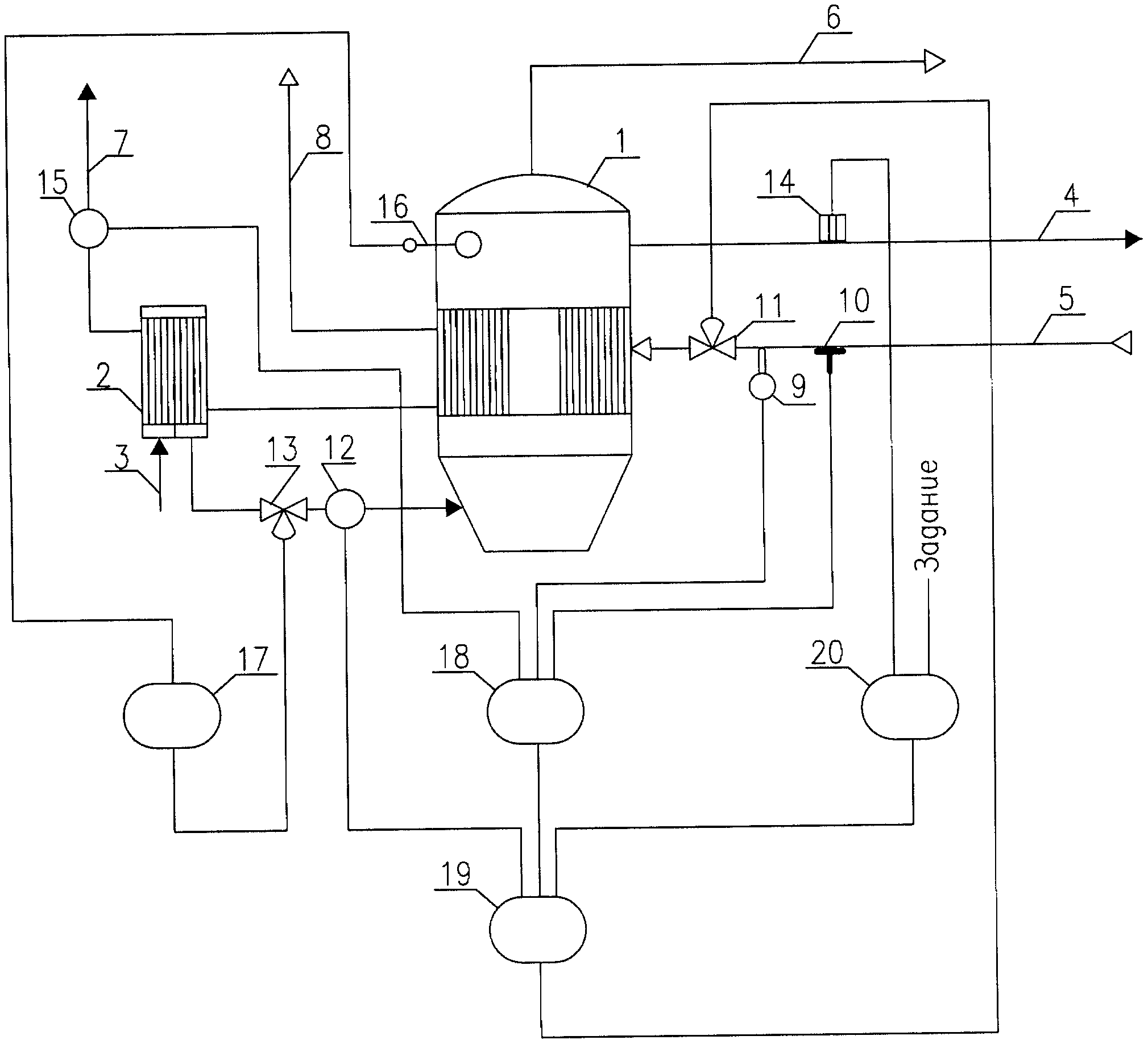
Полезная модель иллюстрируется схемой.The utility model is illustrated by a diagram.
Устройство для автоматического управления выпарной установкой состоит из выпарного аппарата 1, теплообменника 2, трубопровода 3 исходного раствора, трубопровода 4 упаренного раствора, трубопровода 5 греющего пара, трубопровода 6 вторичного пара, трубопровода 7 конденсата греющего пара и трубопровода 8 неконденсирующихся газов. На трубопроводе 5 греющего пара размещены первичный преобразователь температуры 9 греющего пара, первичный преобразователь давления 10 и регулирующий клапан 11 подачи греющего пара. На трубопроводе 3 исходного раствора размещены расходомер исходного раствора 12 и регулирующий клапан 13 подачи исходного раствора. На трубопроводе 4 упаренного раствора размещен первичный преобразователь концентрации 14. На трубопроводе 7 конденсата греющего пара размещен расходомер 15 конденсата греющего пара. В выпарном аппарате 1 размещен уровнемер 16, который соединен с регулятором уровня 17. Расходомер 15 конденсата греющего пара, первичный преобразователь температуры 9 греющего пара и первичный преобразователь давления 10 соединены с вычислительным устройством 18, которое соединено с регулятором 19 соотношения «расход исходного раствора - расход тепла». Первичный преобразователь концентрации 14 связан с корректирующим регулятором 20, который связан с регулятором 19 соотношения «расход исходного раствора - расход тепла».A device for automatic control of the evaporation plant consists of an
Заявляемое устройство работает следующим образом.The inventive device operates as follows.
В выпарной аппарат 1 через теплообменник 2 поступает исходный раствор по трубопроводу 3. Исходный раствор в теплообменнике 2 нагревают, снижая температуру пропускаемого через него конденсата греющего пара. При заполнении исходным раствором выпарного аппарата 1 до заданного уровня подают греющий пар по трубопроводу 5. Заданный уровень упаренного раствора в выпарном аппарате 1 поддерживают регулятором уровня 17, связанным с регулирующим клапаном 13. Вторичный (выпариваемый) пар удаляется из выпарного аппарата 1 по трубопроводу 6 и происходит концентрирование раствора. Значение концентрации упаренного раствора измеряют первичным преобразователем концентрации 14. Это значение появляется на корректирующем регуляторе 20 и сигнал поступает на один из входов регулятора 19 соотношения «расход исходного раствора - расход тепла». На остальные входы регулятора 19 поступают сигналы от расходомера исходного раствора 12 и вычислительного устройства 18. Вычислительное устройство 18 вычисляет расход тепла по сигналам расходомера 15 конденсата греющего пара, первичного преобразователя температуры 9 и первичного преобразователя давления 10 путем перемножения значения расхода конденсата греющего пара и значения удельной теплоты парообразования, которое вычисляется по аппроксимирующим выражениям. Аппроксимирующие выражения составляют по литературным данным («Таблицы теплофизических свойств воды и водяного пара, М.П. Вукалович и др. - Издательство стандартов, М. - 1969 г.) в зависимости от требующейся точности расчета и от технических возможностей располагаемой вычислительной техники. Соотношение «расход исходного раствора - расход тепла» поддерживают на заданном значении регулятором 19 с помощью регулирующего клапана 11 подачи греющего пара.An initial solution enters the
При изменении расхода греющего пара изменится и расход конденсата греющего пара. Вычислительное устройство 18 определит новое значение расхода тепла с учетом текущих значений температуры и давления греющего пара. Сигнал о значении расхода тепла с выхода вычислительного устройства 18 поступит на второй вход регулятора 19 соотношения, который изменит регулирующим клапаном 11 подачу необходимого количества пара для восстановления заданного соотношения «расход исходного раствора - расход тепла». В таком случае, вмешательство корректирующего регулятора 20 не потребуется.When the flow rate of the heating steam changes, the flow rate of the heating steam condensate also changes.
При изменении уровня упаренного раствора регулятор уровня 17 изменит расход исходного раствора, значение которого от расходомера 12 исходного раствора поступит на вход регулятора соотношения 19. Регулятор 19 в соответствии с заданным соотношением изменит подачу греющего пара в выпарной аппарат 1.When changing the level of one stripped off solution, the
При отклонении концентрации упаренного раствора от заданного значения, корректирующий регулятор 20 изменит задание регулятору соотношения 19. При увеличении концентрации упаренного раствора корректирующий регулятор 20 задаст новое - увеличенное соотношение «расход исходного раствора - расход тепла», и регулятор 19 соотношения уменьшит регулирующим клапаном 11 подачу пара в выпарной аппарат 1. При уменьшении концентрации упаренного раствора корректирующий регулятор 20 задаст новое - уменьшенное соотношение «расход исходного раствора - расход тепла», и регулятор соотношения 19 увеличит регулирующим клапаном 11 подачу пара в выпарной аппарат 1.If the concentration of one stripped off solution deviates from the set value, the correcting
Заданные значения исходного раствора, расхода пара определяются при конструкторской разработке выпарной установки и зависят от физико-химических свойств упариваемого раствора и требующейся производительности установки.The set values of the initial solution, steam flow rate are determined during the design development of the evaporator and depend on the physicochemical properties of the evaporated solution and the required plant capacity.
При использовании заявляемого устройства в производстве возникают следующие технические преимущества:When using the inventive device in production, the following technical advantages arise:
- устойчивость работы устройства для автоматического управления выпарной установкой;- the stability of the device for automatic control of the evaporator;
- повышение точности вычисления соотношения «расход тепла - расход сырья»;- improving the accuracy of calculating the ratio "heat consumption - consumption of raw materials";
- повышение продолжительности межпромывочного периода выпарной установки за счет замедления образования накипи на греющей поверхности и, как следствие, повышение производительности установки.- increasing the duration of the inter-washing period of the evaporation plant by slowing the formation of scale on the heating surface and, as a result, increasing the productivity of the plant.
Claims (1)
Priority Applications (1)
| Application Number | Priority Date | Filing Date | Title |
|---|---|---|---|
| RU2013127974/05U RU134814U1 (en) | 2013-06-18 | 2013-06-18 | DEVICE FOR AUTOMATIC CONTROL OF EVAPORATOR |
Applications Claiming Priority (1)
| Application Number | Priority Date | Filing Date | Title |
|---|---|---|---|
| RU2013127974/05U RU134814U1 (en) | 2013-06-18 | 2013-06-18 | DEVICE FOR AUTOMATIC CONTROL OF EVAPORATOR |
Publications (1)
| Publication Number | Publication Date |
|---|---|
| RU134814U1 true RU134814U1 (en) | 2013-11-27 |
Family
ID=49625249
Family Applications (1)
| Application Number | Title | Priority Date | Filing Date |
|---|---|---|---|
| RU2013127974/05U RU134814U1 (en) | 2013-06-18 | 2013-06-18 | DEVICE FOR AUTOMATIC CONTROL OF EVAPORATOR |
Country Status (1)
| Country | Link |
|---|---|
| RU (1) | RU134814U1 (en) |
-
2013
- 2013-06-18 RU RU2013127974/05U patent/RU134814U1/en active
Similar Documents
| Publication | Publication Date | Title |
|---|---|---|
| JP5431382B2 (en) | Evaporative load control system for dryer | |
| CN205593195U (en) | High security boiler liquid level control system | |
| RU134814U1 (en) | DEVICE FOR AUTOMATIC CONTROL OF EVAPORATOR | |
| CN106805282A (en) | A kind of method for controlling water content of chimneying formula dried material | |
| RU2534239C1 (en) | Method for automatic control of evaporation process in evaporation installation | |
| CN104047032B (en) | Method for automatically adjusting energy balance of aluminum electrolysis cell | |
| JP6500585B2 (en) | Measurement system and method | |
| RU2294556C1 (en) | Device for automatic control over semi-continuous action reactor | |
| WO2020248167A2 (en) | Method for calculating flash evaporation speed of flash evaporation procedure in aluminum oxide evaporation process | |
| CN108375310B (en) | A kind of vacuum furnace beacon flint control method | |
| CN113960109A (en) | Self-feedback online monitoring system and method for dryness of wet steam | |
| JP2011179708A (en) | Method and device for controlling water level in boiler | |
| RU2665515C1 (en) | Method for automatically controlling crystallization process in a multi-body evaporator and device for carrying it out | |
| CN104976602A (en) | Steam-heater controlling method | |
| JP6025111B2 (en) | Steam flow measurement method and heat supply system | |
| CN107817209B (en) | Dynamic simulation device for testing performance of scale and corrosion inhibitor and control method thereof | |
| CN203181983U (en) | Tobacco moistening machine | |
| CN207457863U (en) | The temperature control system of acetic synthesis reactor | |
| CN206990027U (en) | A kind of steam turbine main steam flow on-Line Monitor Device | |
| JP6531476B2 (en) | Wetness measurement system and method | |
| RU104475U1 (en) | DEVICE OF AUTOMATIC REGULATION BY THE RECTIFICATION PROCESS | |
| CN203797856U (en) | Indoor constant-temperature constant-humidity system | |
| RU2565611C1 (en) | Control method of removal of liquid and gaseous phases from well fluid separator reservoir | |
| JP6113947B2 (en) | Steam flow measurement method and heat supply system | |
| SU558042A1 (en) | Method for automatic control of heat supply to columns of a screening apparatus |