RU131978U1 - FIRE EXTINGUISHING INSTALLATION - Google Patents
FIRE EXTINGUISHING INSTALLATION Download PDFInfo
- Publication number
- RU131978U1 RU131978U1 RU2013112388/12U RU2013112388U RU131978U1 RU 131978 U1 RU131978 U1 RU 131978U1 RU 2013112388/12 U RU2013112388/12 U RU 2013112388/12U RU 2013112388 U RU2013112388 U RU 2013112388U RU 131978 U1 RU131978 U1 RU 131978U1
- Authority
- RU
- Russia
- Prior art keywords
- fire
- pipeline
- installation
- pipe
- plug
- Prior art date
Links
Images

Abstract
1. Установка пожаротушения, включающая элемент трубопровода, соединенного с пожарными гидрантами, содержащими запорное устройство, связанное с выходным патрубком для соединения с пожарным рукавом, устройство обогрева элемента трубопровода, дверной шкаф для размещения элементов установки, лотки для помещения в них пожарных рукавов и стволов, полый присоединительный элемент, размещенный внутри элемента трубопровода с возможностью подсоединения к нему запорного устройства, отличающаяся тем, что один из концов элемента трубопровода закрыт заглушкой, а другой конец элемента трубопровода выполнен с возможностью подсоединения к нему сухотруба.2. Установка по п.1, отличающаяся тем, что в качестве заглушки выбрана сферическая заглушка.3. Установка по п.1, отличающаяся тем, что в качестве заглушки выбрана фланцевая заглушка.4. Установка по п.1, отличающаяся тем, что другой конец элемента трубопровода снабжен фланцем.1. Fire extinguishing installation, including an element of a pipeline connected to fire hydrants containing a locking device associated with an outlet pipe for connecting to a fire hose, a heating device for a pipeline element, a door cabinet for placing installation elements, trays for placing fire hoses and trunks in them, a hollow connecting element placed inside the pipeline element with the possibility of connecting a locking device to it, characterized in that one of the ends of the pipeline element is closed It is plugged, and the other end of the pipeline element is configured to connect a dry pipe to it. 2. Installation according to claim 1, characterized in that a spherical plug is selected as a stub. 3. Installation according to claim 1, characterized in that the flange plug is selected as a plug. Installation according to claim 1, characterized in that the other end of the pipe element is provided with a flange.
Description
Полезная модель относится к пожарной технике, а именно к установкам пожаротушения, и предназначена для подачи воды с помощью сухотруба к удаленным от трубопровода пожарного водовода очагам пожара. Может быть использована для пожаротушения в условиях низких температур.The utility model relates to fire fighting equipment, namely to fire extinguishing installations, and is intended for supplying water by means of a dry pipe to fire centers remote from the fire conduit pipeline. It can be used for fire fighting at low temperatures.
Известна система пожаротушения площадок слива нефтепродуктов, включающая модульную установку пенного тушения и «сухотрубы подачи» компонентов в зону тушения через пеногенераторы, в которой с целью ограничения объема тушения, площадка слива выполнена в виде бокса, каркас которого сформирован из «сухотрубов подачи», а ограждающие поверхности из сетки «рабица» (Патент РФ на полезную модель №75949, МПК А62С 5/02. Опубл. 10.09.2008 г.).A known fire extinguishing system for oil product discharge platforms, including a modular installation of foam extinguishing and a “dry supply pipe” of components into the extinguishing zone through foam generators, in which, in order to limit the extinguishing, the discharge platform is made in the form of a box, the frame of which is formed of “dry supply pipes”, and the enclosing the surface of the grid "netting" (RF Patent for utility model No. 75949, IPC
Известно также устройство противопожарной защиты резервуаров для хранения жидких горючих веществ, характеризующееся тем, что в резервуаре для хранения жидких горючих веществ в систему пожаротушения установлен, по меньшей мере, один перфорированный сухотруб, состоящий из, по меньшей мере, одной секции, размещенной внутри резервуара и проходящей сквозь слой горючего вещества таким образом, что один конец сухотруба присоединен к системе пожаротушения, а другой конец сухотруба выступает над максимальным уровнем взлива жидкого горючего вещества, хранящегося в резервуаре. При этом секции сухотруба покрыты синтетической пленкой или синтетическим покрытием для обеспечения герметичности внутреннего пространства сухотруба от хранимого жидкого горючего вещества с возможностью раскрытия перфорации сухотруба под воздействием факторов пожара непосредственно над поверхностью жидкого горючего вещества и/или в зоне горения в непосредственной близости от поверхности, независимо от уровня взлива жидкости горючего вещества в резервуаре (Патент РФ на изобретение №2425702, МПК А62С 3/06, А62С 35/00. Опубл. 10.08.2011 г.).A device for the fire protection of tanks for storing liquid combustible substances is also known, characterized in that at least one perforated dry pipe is installed in the tank for storing liquid combustible substances in the fire extinguishing system, consisting of at least one section located inside the tank and passing through a layer of combustible substance in such a way that one end of the dry pipe is connected to the fire extinguishing system, and the other end of the dry pipe extends above the maximum level of liquid fuel spillage substance stored in the tank. The sections of the dry pipe are covered with a synthetic film or synthetic coating to ensure the tightness of the internal space of the dry pipe from the stored liquid combustible with the possibility of opening perforation of the dry pipe under the influence of fire factors directly above the surface of the liquid combustible substance and / or in the combustion zone in the immediate vicinity of the surface, regardless of the level of liquid spillage of a combustible substance in the tank (RF Patent for the invention No. 2425702, IPC А62С 3/06, А62С 35/00. Published. 08/10/2011).
Однако, и известная система пожаротушения, и данное устройство предназначены для пенного тушения пожаров в замкнутых объемах.However, both the known fire extinguishing system and this device are designed for foam extinguishing fires in confined spaces.
Наиболее близкой к предлагаемой по своей технической сущности является установка пожаротушения, включающая элемент трубопровода, соединенный с пожарными гидрантами, содержащими запорное устройство, связанное с выходным патрубком для соединения с пожарным рукавом, устройство обогрева элемента трубопровода, дверной шкаф для размещения элементов установки, лотки для помещения в них пожарных рукавов и стволов, в которую дополнительно введен полый присоединительный элемент, размещенный внутри элемента трубопровода с возможностью подсоединения к нему запорного устройства (Патент РФ на полезную модель №113970, МПК А62С 35/20. Опубл. 10.03.2012 г.).Closest to the proposed in its technical essence is a fire extinguishing installation, including a pipe element connected to fire hydrants, containing a locking device associated with an outlet pipe for connecting with a fire hose, a heating device for a pipeline element, a door cabinet for placing installation elements, room trays in them fire hoses and trunks, into which an additional hollow connecting element is placed, which is placed inside the pipeline element with the possibility of connecting of the connections to it a closure device (Russian utility model patent №113970, IPC A62S 35/20. Publ. of 10.03.2012).
Но эта установка, врезанная в замкнутый пожарный водовод, содержащий трубопровод, насос и трубопроводную арматуру, не обеспечивает тушение удаленных от трубопровода пожарного водовода очагов пожара.But this installation, embedded in a closed fire conduit containing a pipeline, a pump, and pipe fittings, does not extinguish fires remote from the fire conduit.
Задачей, на решение которой направлена заявленная полезная модель, является обеспечение тушения удаленных от трубопровода пожарного водовода очагов пожара.The task to which the claimed utility model is directed is to extinguish fire centers remote from the fire conduit.
Технический результат заключается в создании возможности подсоединения сухотруба к установке пожаротушения.The technical result consists in creating the possibility of connecting the dry pipe to the fire extinguishing installation.
Поставленная задача решается тем, что в установке пожаротушения, включающей элемент трубопровода, соединенного с пожарными гидрантами, содержащими запорное устройство, связанное с выходным патрубком для соединения с пожарным рукавом, устройство обогрева элемента трубопровода, дверной шкаф для размещения элементов установки, лотки для помещения в них пожарных рукавов и стволов, полый присоединительный элемент, размещенный внутри элемента трубопровода с возможностью подсоединения к нему запорного устройства, один из концов элемента трубопровода закрыт заглушкой, а другой конец элемента трубопровода выполнен с возможностью подсоединения к нему сухотруба.The problem is solved in that in a fire extinguishing installation, including a pipe element connected to fire hydrants, containing a locking device associated with an outlet pipe for connecting to a fire hose, a heating device for a pipeline element, a door cabinet for placing installation elements, trays for placement in them fire hoses and trunks, a hollow connecting element placed inside the pipeline element with the possibility of connecting a locking device to it, one of the ends of the element t uboprovoda closed cap, and the other end of the conduit member is adapted to connect thereto suhotruba.
Заглушка на одном из концов элемента трубопровода и этот элемент становятся составляющей сухотруба, способствуя тушению очагов пожара, удаленных от установки.A plug at one of the ends of the pipeline element and this element become a component of the dry pipe, contributing to extinguishing fires remote from the installation.
При этом в качестве заглушки может быть выбрана, например, сферическая или фланцевая заглушка.In this case, for example, a spherical or flange plug can be selected as a plug.
Выполнение другого конца элемента трубопровода с возможностью подсоединения к нему сухотруба позволяет тушить удаленные от трубопровода пожарного водовода очаги пожара. Другой конец элемента трубопровода снабжен, например, фланцем для обеспечения фланцевого соединения с сухотрубом.The execution of the other end of the pipeline element with the possibility of connecting a dry pipe to it allows you to extinguish the fires remote from the fire hydrant pipeline. The other end of the pipe element is provided, for example, with a flange for providing a flange connection to the dry pipe.
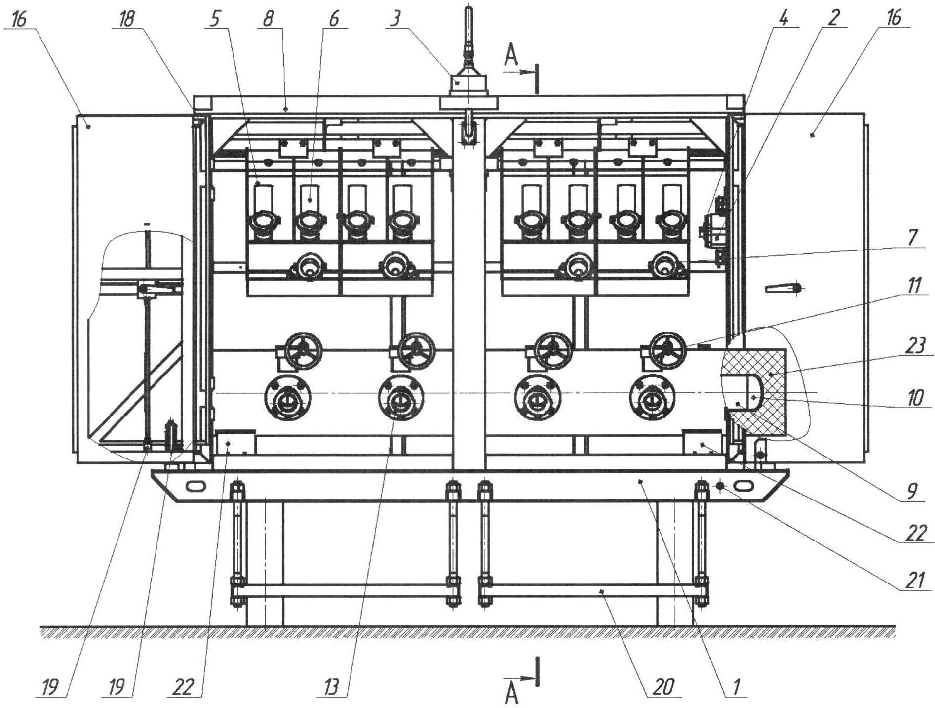
На фиг.1 показана установка пожаротушения, общий вид; на фиг.2 - сечение А-А общего вида установки пожаротушения.Figure 1 shows the installation of fire extinguishing, General view; figure 2 is a section aa of a General view of the fire extinguishing installation.
Установка содержит (фиг.1, 2) шкаф 1, пульт включения/выключения 2 насоса (не показан), светильник 3 и пульт его включения/выключения 4, лотки 5 для размещения пожарных рукавов 6 и стволов 7, объединенных попарно и прикрепленных к внутренней поверхности крыши 8 шкафа 1, элемент трубопровода 9 с заглушкой 10, соединенный с пожарным гидрантом 11, содержащим запорное устройство 12, связанное с выходным патрубком 13. Выходной патрубок 13 обеспечивает присоединение пожарного рукава 6. Запорное устройство 12 также соединено и с полым присоединительным элементом 14, размещенным внутри элемента трубопровода 9.The installation contains (Fig. 1, 2) a
Элемент трубопровода 9 снабжен устройством обогрева 15, состоящим, например, из греющего кабеля или трубы теплоспутника, входящих при монтаже установки в общую систему обогрева трубопровода (не показана). Двери 16 шкафа 1 складные, включают секции 17, 18 и закрепляются в открытом или закрытом положении фиксаторами 19. Шкаф 1 имеет регулируемые по высоте ступеньки 20 и заземление 21. А элемент трубопровода 9 жестко прикреплен к опорам 22, выполненным с возможностью их перемещения по основанию шкафа 1 при тепловом расширении элемента трубопровода 9, и снабжен тепловой изоляцией 23.The element of the
Установка работает следующим образом.Installation works as follows.
Присоединяют оснащенный задвижкой и сливным элементом сухотруб (не показаны), отходящий от пожарного водовода (не показан), подающего огнетушащую жидкость для тушения очага возгорания, к концу элемента трубопровода 9 без заглушки 10.A dry pipe (not shown) equipped with a valve and a drain element is connected, which leaves the fire line (not shown), which supplies the extinguishing fluid to extinguish the fire, to the end of the
Открывают при тушении пожара двери 16 шкафа 1, складывают их секции 17, 18 и закрепляют фиксаторами 19.When extinguishing a fire, the
Вынимают из лотков 5 пожарные рукава 6 и стволы 7, соединяют их между собой и присоединяют к выходному патрубку 13 соответствующего пожарного гидранта 11.
Включают с помощью пульта 2 насос, повышающий давление в пожарном водоводе. Затем открывают задвижку сухотруба, обеспечивая поступление воды в него и в элемент трубопровода 9 с заглушкой 10.Using the
После чего открывают запорное устройство 12 пожарного гидранта 11, и огнетушащую жидкость, положительная температура которой поддерживается с помощью устройства обогрева 15, подают через подсоединенные к выходному патрубку 13 развернутые пожарные рукава 6 и стволы 7 к месту тушения.After that, the
При необходимости в темное время суток с помощью пульта 4 включают светильник 3.If necessary, in the dark using the
Claims (4)
Priority Applications (1)
| Application Number | Priority Date | Filing Date | Title |
|---|---|---|---|
| RU2013112388/12U RU131978U1 (en) | 2013-03-19 | 2013-03-19 | FIRE EXTINGUISHING INSTALLATION |
Applications Claiming Priority (1)
| Application Number | Priority Date | Filing Date | Title |
|---|---|---|---|
| RU2013112388/12U RU131978U1 (en) | 2013-03-19 | 2013-03-19 | FIRE EXTINGUISHING INSTALLATION |
Publications (1)
| Publication Number | Publication Date |
|---|---|
| RU131978U1 true RU131978U1 (en) | 2013-09-10 |
Family
ID=49165099
Family Applications (1)
| Application Number | Title | Priority Date | Filing Date |
|---|---|---|---|
| RU2013112388/12U RU131978U1 (en) | 2013-03-19 | 2013-03-19 | FIRE EXTINGUISHING INSTALLATION |
Country Status (1)
| Country | Link |
|---|---|
| RU (1) | RU131978U1 (en) |
Cited By (1)
| Publication number | Priority date | Publication date | Assignee | Title |
|---|---|---|---|---|
| RU188164U1 (en) * | 2018-07-30 | 2019-04-01 | Игорь Валерьевич Медведев | Locking device for fire connection heads |
-
2013
- 2013-03-19 RU RU2013112388/12U patent/RU131978U1/en active
Cited By (1)
| Publication number | Priority date | Publication date | Assignee | Title |
|---|---|---|---|---|
| RU188164U1 (en) * | 2018-07-30 | 2019-04-01 | Игорь Валерьевич Медведев | Locking device for fire connection heads |
Similar Documents
| Publication | Publication Date | Title |
|---|---|---|
| US2558694A (en) | Storage tank | |
| US9228303B2 (en) | Device for a helicopter deck | |
| US7909111B1 (en) | Outdoor fire prevention system and associated method | |
| RU131978U1 (en) | FIRE EXTINGUISHING INSTALLATION | |
| RU149130U1 (en) | FIRE EXTINGUISHING INSTALLATION | |
| KR101730108B1 (en) | Connecting apparatus for fire fighting sprinkler of apartment house | |
| RU75580U1 (en) | INSTALLATION OF GAS EXTINGUISHING | |
| RU160177U1 (en) | FIRE HYDRANT BLOCK | |
| RU195409U1 (en) | HYDRANT FIRE LAND | |
| CN204134082U (en) | A kind of steam annihilator of hot oil pump sealing leak point | |
| CN106193176A (en) | A kind of hydromechanical installer engineering construction method | |
| RU140479U1 (en) | FIRE HYDRANT MODULE | |
| RU113970U1 (en) | FIRE EXTINGUISHING INSTALLATION | |
| RU167941U1 (en) | PIPELINE OUTPUT EDS IN FIRE EXTINGUISHING INSTALLATION | |
| RU2658796C2 (en) | Fire protection system of facility | |
| RU159429U1 (en) | FIRE HYDRANT CAMERA | |
| KR101174752B1 (en) | System for supressing of damage by cold wether for hot water boiler | |
| RU150587U1 (en) | FIRE HYDRANT MODULE | |
| RU150588U1 (en) | FIRE HYDRANT MODULE | |
| RU41982U1 (en) | FIRE FIGHTING PLANT | |
| KR101389799B1 (en) | Ground water supply system for forest fire prenention using ground water layer | |
| RU127642U1 (en) | FIRE HYDRANT MODULE | |
| RU134057U1 (en) | INSTALLATION OF FIRE EXTINGUISHING IN VERTICAL STEEL TANKS AND THEIR DUMPING WITH A DEVICE FOR PREVENTING EXPLOSION WHEN HEATING A PETROLEUM PRODUCT | |
| RU117298U1 (en) | INSTALLING UNDERSTANDING FIRE EXTINGUISHING IN RESERVOIRS WITH OIL PRODUCTS | |
| RU141291U1 (en) | FIRE EXTINGUISHING SYSTEM IN VERTICAL RESERVOIRS FOR STORAGE OF OIL PRODUCTS IN POINTS OF TEMPORARY ACCOMMODATION OF POPULATION AFFECTED BY AN EMERGENCY |