RU129052U1 - ELECTRIC CAR WIND GENERATOR - Google Patents
ELECTRIC CAR WIND GENERATOR Download PDFInfo
- Publication number
- RU129052U1 RU129052U1 RU2013100737/11U RU2013100737U RU129052U1 RU 129052 U1 RU129052 U1 RU 129052U1 RU 2013100737/11 U RU2013100737/11 U RU 2013100737/11U RU 2013100737 U RU2013100737 U RU 2013100737U RU 129052 U1 RU129052 U1 RU 129052U1
- Authority
- RU
- Russia
- Prior art keywords
- generator
- blades
- electric vehicle
- mounting rail
- pulleys
- Prior art date
Links
Images


Classifications
-
- Y—GENERAL TAGGING OF NEW TECHNOLOGICAL DEVELOPMENTS; GENERAL TAGGING OF CROSS-SECTIONAL TECHNOLOGIES SPANNING OVER SEVERAL SECTIONS OF THE IPC; TECHNICAL SUBJECTS COVERED BY FORMER USPC CROSS-REFERENCE ART COLLECTIONS [XRACs] AND DIGESTS
- Y02—TECHNOLOGIES OR APPLICATIONS FOR MITIGATION OR ADAPTATION AGAINST CLIMATE CHANGE
- Y02B—CLIMATE CHANGE MITIGATION TECHNOLOGIES RELATED TO BUILDINGS, e.g. HOUSING, HOUSE APPLIANCES OR RELATED END-USER APPLICATIONS
- Y02B10/00—Integration of renewable energy sources in buildings
- Y02B10/30—Wind power
-
- Y—GENERAL TAGGING OF NEW TECHNOLOGICAL DEVELOPMENTS; GENERAL TAGGING OF CROSS-SECTIONAL TECHNOLOGIES SPANNING OVER SEVERAL SECTIONS OF THE IPC; TECHNICAL SUBJECTS COVERED BY FORMER USPC CROSS-REFERENCE ART COLLECTIONS [XRACs] AND DIGESTS
- Y02—TECHNOLOGIES OR APPLICATIONS FOR MITIGATION OR ADAPTATION AGAINST CLIMATE CHANGE
- Y02E—REDUCTION OF GREENHOUSE GAS [GHG] EMISSIONS, RELATED TO ENERGY GENERATION, TRANSMISSION OR DISTRIBUTION
- Y02E10/00—Energy generation through renewable energy sources
- Y02E10/70—Wind energy
- Y02E10/74—Wind turbines with rotation axis perpendicular to the wind direction
Landscapes
- Wind Motors (AREA)
Abstract
1. Ветрогенератор электромобиля, который содержит, как минимум один генератор, как минимум один вал ротора, как минимум один шкив, лопасти, отличающийся выполнением вала ротора удлиненным, выступающим с двух сторон генератора, горизонтальным расположением вала к вертикальной оси электромобиля, перпендикулярным вектору движения электромобиля; наличием крепежной рейки; каждый генератор жестко установлен на крепежную рейку, как минимум два шкива с лопастями установлены на вал ротора по одному с каждой стороны генератора, крепежная рейка жестко крепится к корпусу электромобиля ниже уровня крыши корпуса, при этом крыша корпуса электромобиля имеет прорези в виде прямоугольных отверстий для свободного выхода лопастей, количество и расположение прорезей соответствует количеству и расположению шкивов, установленных на валу ротора, количество шкивов соответствует как минимум двум на каждый генератор, количество генераторов зависит от требуемой мощности подзарядки аккумуляторов, при этом каждый генератор установлен перпендикулярно потоку воздуха.2. Ветрогенератор электромобиля по п.1, отличающийся тем, что содержит дополнительную крепежную рейку во второй ряд, при этом генераторы на второй дополнительной крепежной рейке устанавливаются таким образом, чтобы шкивы с лопастями второго ряда не совпадали с расположением шкивов первого ряда, прорези в корпусе под лопасти выполнены в шахматном порядке и позволяют использовать воздушный поток, не заслоненный лопастями первого ряда.3. Ветрогенератор электромобиля по п.1, отличающийся тем, что крепежная рейка изготовлена из металлического проката.4. Ветрогенератор �1. The electric vehicle’s wind generator, which contains at least one generator, at least one rotor shaft, at least one pulley, blades, characterized by the rotor shaft being elongated, protruding from both sides of the generator, with a horizontal arrangement of the shaft to the vertical axis of the electric vehicle perpendicular to the electric vehicle’s motion vector ; the presence of a mounting rail; each generator is rigidly mounted on the mounting rail, at least two pulleys with blades are mounted on the rotor shaft one on each side of the generator, the mounting rail is rigidly attached to the electric car body below the level of the roof of the body, while the roof of the electric car body has slots in the form of rectangular holes for free the exit of the blades, the number and location of slots corresponds to the number and location of pulleys mounted on the rotor shaft, the number of pulleys corresponds to at least two for each generator, The number of generators depends on the required battery recharging power, with each generator installed perpendicular to the air flow. 2. The electric vehicle wind generator according to claim 1, characterized in that it contains an additional mounting rail in the second row, while the generators on the second additional mounting rail are installed so that the pulleys with the second row of blades do not coincide with the location of the pulleys of the first row, cuts in the housing under the blades made in a checkerboard pattern and allow the use of air flow not obscured by the first row of blades. 3. The electric vehicle wind generator according to claim 1, characterized in that the mounting rail is made of rolled metal. Wind generator �
Description
Полезная модель относится к ветроэнергетическим устройствам, работающим на основе использования встречного потока воздуха для выработки электроэнергии и может быть использована для автономного и бесперебойного питания электромобиля, в частности для подзарядки аккумуляторных батарей.The utility model relates to wind power devices based on the use of oncoming air flow to generate electricity and can be used for autonomous and uninterrupted power supply of an electric vehicle, in particular for recharging rechargeable batteries.
Известно техническое решение по патенту RU 2375212 C1 B60K 16/00 F03D 3/00, опубл. 10.12.2009 г., АВТОМОБИЛЬНЫЙ ВЕТРОГЕНЕРАТОР, который содержит вал, генератор, установленный на опоре с обмотками на валу, многогранную призму с насадкой лопастей с присоединением конусной части. Перед конусной частью установлен козырек, расположенный под углом и закрепленный за кабину. Лопасти закреплены сваркой или болтами под углом к граням призмы с возможностью их поворота на 90 градусов с прижатием лопастей штормовым ветром плотно к поверхности граней призмы. Лопасти имеют пружины, один конец которых соединен с лопастью, а второй - с гранью призмы. Причем пружины подобраны таким образом, что обеспечивают при штормовом ветре поворот лопастей до положения, при котором их поверхности плотно прижимаются к поверхности граней. Изобретение обеспечивает использование двух видов ветровых потоков, а именно искусственного ветра при движении автомобиля и естественного ветра при стоянках. При использовании ветровых потоков устройство работает как самоуправляемое. Недостатки: сложность конструкции, недостаточная эффективность использования воздушных потоков, что ведет к низкой производительности генератора.Known technical solution according to patent RU 2375212 C1 B60K 16/00
Известно техническое решение по заявке на патент RU 2005127106 А В60К 1/00, опубл. 10.03.2007 г., по которому ВЕТРОГЕНЕРАТОР ДЛЯ ЭЛЕКТРОМОБИЛЯ, содержащий по меньшей мере один модуль ветрогенератора и выпрямитель, в котором модуль ветрогенератора установлен на электромобиле, дополнительно содержащий плоский кожух, множество воздушных каналов и множество небольшие ветряных энергоблоков, установленных в воздушных каналах, воздуховпускные отверстия в указанном множестве воздушных каналов, направленные вперед по направлению движения электромобиля, воздуховыпускные отверстия во множестве воздушных каналов, направленные в сторону задней части электромобиля, при движении электромобиля воздух входит в указанные воздуховпускные отверстия воздушных каналов и приводит в движение множество ветряных энергоблоков, чтобы выработать электроэнергию, и вырабатываемая электроэнергия подается через выпрямитель на тяговый электродвигатель электромобиля. Между выпрямителем и тяговым электродвигателем установлено электронное реле, причем электрическая цепь электронного реле соединена с комплектом аккумуляторных батарей электромобиля, следовательно, когда электроэнергия, вырабатываемая модулем ветрогенератора недостаточна для движения электромобиля, комплект аккумуляторных батарей служит для компенсации недостаточной мощности, когда модуль ветрогенератора вырабатывает избыточную электроэнергию, дополнительная электроэнергия может быть использована для подзаряда аккумуляторной батареи. Недостатки: сложная конструкция, сложная система расположения воздушных каналов не обеспечивает поток, необходимый для выработки электроэнергии, соответственно, низкая производительность известной конструкции ветрогенератора.A technical solution is known for patent application RU 2005127106 A
Наиболее близким к заявляемому является техническое решение по патенту 115019 U1 F03D 3/00, опубл. 20.04.2012 г., ВЕТРОГЕНЕРАТОР ЭЛЕКТРОМОБИЛЯ, который содержит ветроприемник, выполненный в виде конфузора, цилиндрическую камеру, в которой размещены ветровые колеса, сборный воздушный канал и электрогенераторы, размещенные вне цилиндрической камеры, причем он снабжен системой воздушного охлаждения, ветроприемник имеет верхнюю и нижнюю камеры, выполненные в виде конфузоров с тангенциальным подходом искусственного воздушного потока к ветровым колесам, которые установлены в цилиндрической камере, причем верхнее ветровое колесо соединено с внутренним валом, а нижнее ветровое колесо соединено с внешним валом, а за пределами цилиндрической камеры к этим коаксиально установленным валам прикреплены роторы в виде дисков с П-образным поперечным сечением, к внутренним стенкам которых прикреплены постоянные магниты, причем внутренний вал вращается по часовой стрелки, а внешний вал вращается против часовой стрелки вокруг статоров - магнитопроводов с рабочими обмотками, которые имеют узлы для крепления к внешним конструкциям, а сборный воздушный канал непосредственно сообщается с атмосферой в кормовой зоне электромобиля. Система воздушного охлаждения выполнена в виде вытяжного короба соединенного с трубой, выходное отверстие которой размешено в днище нижней камеры. Ветровые колеса имеют одинаковый диаметр, выполнены из прочного синтетического материала и имеют форму цилиндра с внешними прямоугольными вырезами в виде полусегмента, лежащего между двумя смежными радиусами и занимает площадь между перпендикуляром, опущенным из конца радиуса на другой радиус, и дугой, заключенной между этими радиусами. Коаксиально установленные валы выполнены из стали повышенной прочности. Постоянные магниты имеют форму кругового кольца с прямоугольным поперечным сечением и выполнены из редкоземельных элементов (самарий Sa, кобальт Со). Магнитопровод имеет двадцать четыре Т-образных секторных консолей, на которых размещены рабочие обмотки, причем каждые восемь рабочих обмоток подключены последовательно через две и образуют круговую рабочую обмотку, таких обмоток три. Станина магнитопровода выполнена из немагнитного материала.Closest to the claimed is a technical solution according to patent 115019 U1 F03D 3/00, publ. 04/20/2012, ELECTRIC CAR WIND-GENERATOR, which contains a wind receiver made in the form of a confuser, a cylindrical chamber in which wind wheels are placed, a prefabricated air channel and electric generators located outside the cylindrical chamber, and it is equipped with an air cooling system, the wind receiver has an upper and lower chambers made in the form of confusers with a tangential approach of artificial air flow to the wind wheels, which are installed in a cylindrical chamber, the upper wind wheel being connected to the inner shaft, and the lower wind wheel is connected to the outer shaft, and outside the cylindrical chamber to these coaxially mounted shafts are rotors in the form of disks with a U-shaped cross section, permanent magnets are attached to the inner walls of which, the inner shaft rotates clockwise, and the external shaft rotates counterclockwise around the stators - magnetic cores with working windings, which have units for fastening to external structures, and the prefabricated air channel directly communicates with atmosphere in the stern area of an electric vehicle. The air cooling system is made in the form of an exhaust duct connected to a pipe, the outlet of which is placed in the bottom of the lower chamber. Wind wheels have the same diameter, are made of durable synthetic material and have the shape of a cylinder with external rectangular cutouts in the form of a half segment lying between two adjacent radii and occupy the area between the perpendicular dropped from the radius end to another radius and the arc enclosed between these radii. Coaxially mounted shafts are made of high strength steel. Permanent magnets have the shape of a circular ring with a rectangular cross section and are made of rare earth elements (Samarium Sa, cobalt Co). The magnetic circuit has twenty-four T-shaped sector consoles on which the working windings are located, and each eight working windings are connected in series through two and form a circular working winding, there are three such windings. The base of the magnetic circuit is made of non-magnetic material.
Недостатком прототипа является сложная конструкция, включающая воздуховод с нормальным, малоэффективным натеканием искусственного воздушного потока на ветровое колесо и сборный воздушный канал с боковыми рукавами, которые усложняют конструкцию сборного воздушного канала и создают незначительный аэродинамический эффект. Генераторы установлены вертикально, что затрудняет вращение оси, снижает производительность. Работает только одна половина оси генераторов - производительность очень низкая. Система воздушных камер усложняет, утяжеляет конструкцию, не достигая своей цели - скорость воздушного потока не увеличивается.The disadvantage of the prototype is a complex structure, including a duct with a normal, inefficient leakage of artificial air flow onto the wind wheel and a prefabricated air duct with side arms, which complicate the design of the prefabricated air duct and create a slight aerodynamic effect. Generators are installed vertically, which makes rotation of the axis difficult, and reduces productivity. Only one half of the generator axis works - performance is very low. The system of air chambers complicates, makes the structure heavier, not reaching its goal - the air flow rate does not increase.
Указанные недостатки решает заявляемая полезная модель.These shortcomings are solved by the claimed utility model.
Техническая задача, на решение которой направлена данная полезная модель, заключается в устранении недостатков прототипа путем упрощения конструкции, отказа от неэффективного расположения генераторов, от конфузора, от воздушных камер, и повышении эффективности, производительности, снижении себестоимости изготовления.The technical problem, which this utility model is aimed at, is to eliminate the disadvantages of the prototype by simplifying the design, rejecting the inefficient arrangement of generators, confuser, air chambers, and increasing efficiency, productivity, and reducing manufacturing costs.
Для решения технической задачи предлагается конструкция ветрогенератора электромобиля с горизонтальной установкой генераторов, при этом роль воздухоприемника выполняет шкив с лопастями. При движении электромобиля создается мощный поток встречного воздуха, который можно использовать для зарядки аккумуляторных батарей. Для этого используют обычные автомобильные генераторы.To solve the technical problem, we propose the design of an electric vehicle wind generator with horizontal installation of generators, while the pulley with blades serves as an air intake. When the electric vehicle moves, a powerful stream of oncoming air is created, which can be used to charge the batteries. For this, conventional automobile generators are used.
Для того, чтобы использовать встречный поток воздуха, на вал генератора одевают шкив с лопастями, изготовленными из пластмассы, алюминия, титана и т.д. Для увеличения производительности и скорости вращения в заводских условиях удлиняют вал генератора, на вал генератора надевают второй шкив с лопастями (фиг.1, фиг.2, фиг.3, фиг.4). Модернизированные генераторы устанавливают перпендикулярно потоку воздуха, как на электромобилях, так и на ветрогенераторах стационарных (ветряках). Крепежная рейка жестко (например, болтами) крепится к корпусу электромобиля ниже уровня крыши корпуса электромобиля, при этом крыша корпуса электромобиля имеет прорези в виде прямоугольных отверстий для свободного выхода лопастей. Для увеличения мощности на одной крепежной рейке могут быть установлены несколько генераторов, каждый жестко (например, болтами) монтируется к крепежной рейке, при этом каждый генератор содержит удлиненный вал, на каждом из которых с двух сторон от генератора установлен шкив с лопастями. Количество прорезей в виде прямоугольных отверстий в крыше корпуса электромобиля соответствует количеству шкивов, установленных на валу ротора, количество шкивов соответствует как минимум два на каждый генератор, количество генераторов зависит от требуемой мощности, каждый генератор установлен перпендикулярно потоку воздуха.In order to use a counter flow of air, a pulley with blades made of plastic, aluminum, titanium, etc., is put on the generator shaft. To increase productivity and rotation speed in the factory, the generator shaft is extended, a second pulley with blades is put on the generator shaft (Fig. 1, Fig. 2, Fig. 3, Fig. 4). Upgraded generators are installed perpendicular to the air flow, both on electric vehicles and stationary wind generators (windmills). The mounting rail is rigidly (for example, bolted) attached to the electric vehicle body below the level of the roof of the electric vehicle body, while the roof of the electric vehicle body has slots in the form of rectangular holes for free exit of the blades. To increase power, several generators can be installed on one mounting rail, each is rigidly mounted (for example, with bolts) to the mounting rail, and each generator contains an elongated shaft, on each of which a pulley with blades is installed on both sides of the generator. The number of slots in the form of rectangular holes in the roof of the electric vehicle body corresponds to the number of pulleys mounted on the rotor shaft, the number of pulleys corresponds to at least two for each generator, the number of generators depends on the required power, each generator is installed perpendicular to the air flow.
Как частный случай, при требуемой более высокой мощности зарядки аккумуляторов, возможна установка дополнительной крепежной рейки во второй ряд, при этом генераторы устанавливаются таким образом, чтобы шкивы с лопастями второго ряда не совпадали с расположением шкивов второго ряда при проекции вид спереди (вид сзади), прорези в корпусе крыши выполнены в шахматном порядке и позволяют использовать воздушный поток, не заслоняемый лопастями шкивов первого ряда.As a special case, with the required higher battery charging power, it is possible to install an additional mounting rail in the second row, while the generators are installed so that the pulleys with the second row of blades do not coincide with the location of the second row of pulleys in the projection front view (rear view), the slots in the roof housing are staggered and allow the use of an air stream not obscured by the pulleys of the first row of pulleys.
Для примера возьмем вариант установки генератора на крышу электромобиля (фиг.5, фиг.6, фиг.7). для зарядки можно использовать один, два или несколько генераторов в зависимости от мощности аккумуляторных батарей. В качестве генератора используют автомобилильный генератор. Крепежную рейку (фиг.5) изготавливают из металлопроката (например, шинки металлической, уголка и т.д.) Встречным потоком воздуха за счет движения лопастей ротор генератора начнет вращаться и вырабатывать электрический ток. При этом лопасти должны выходить за корпус электромобиля примерно на одну треть, а две трети должны быть закрыты (фиг.7). Чем больше высота и ширина лопастей, тем легче вращение лопастей генераторов. Рекомендуемые формы лопастей - фиг.8, фиг.9, фиг.10, фиг.11.For example, take the option of installing a generator on the roof of an electric vehicle (Fig. 5, Fig. 6, Fig. 7). For charging, you can use one, two or more generators, depending on the power of the batteries. A car generator is used as a generator. The mounting rail (Fig. 5) is made of rolled metal (for example, a metal bar, corner, etc.) With an oncoming air stream due to the movement of the blades, the generator rotor will begin to rotate and generate an electric current. In this case, the blades should extend beyond the body of the electric vehicle by about one third, and two thirds should be closed (Fig. 7). The greater the height and width of the blades, the easier the rotation of the blades of the generators. Recommended shape of the blades - Fig.8, Fig.9, Fig.10, Fig.11.
На электромобилях с установкой второй, сквозной крыши, которая защитит от атмосферных осадков, можно создать эффект турбины. Поток воздуха начнет прижимать лопасти, что позволит увеличить поток воздуха на каждый генератор. Этот принцип, который описан для электромобилей, можно использовать и на стационарных ветрогенераторах (ветряках) для выработки электрической энергии (фиг.12, фиг.13). Ветряк работает по принципу флюгера. Лопасти ветряка прямые и должны быть закрыты защитой примерно на две трети (фиг.12, фиг.13).On electric vehicles with the installation of a second, through roof, which protects against atmospheric precipitation, you can create the effect of a turbine. The air flow will begin to press the blades, which will increase the air flow to each generator. This principle, which is described for electric vehicles, can also be used on stationary wind generators (windmills) to generate electrical energy (Fig. 12, Fig. 13). The windmill works on the principle of a weather vane. The blades of a windmill are straight and should be closed by protection by about two-thirds (Fig. 12, Fig. 13).
Заявляемая полезная модель позволит электромобилям двигаться без дополнительной подзарядки аккумуляторных батарей, позволит снизить затраты на изготовление, повысить производительность ветрогенератора.The inventive utility model will allow electric vehicles to move without additional recharging the batteries, will reduce manufacturing costs, increase the productivity of the wind generator.
Технический результат - упрощение конструкции ветрогенератора, с одновременным повышением его производительности и снижением себестоимости его изготовления.The technical result is a simplification of the design of the wind generator, while increasing its productivity and reducing the cost of its manufacture.
Технический результат достигается за счет конструкции ветрогенератора, который содержит, как минимум один генератор, как минимум один вал ротора, как минимум один шкив, лопасти, отличающийся выполнением вала ротора удлиненным, выступающим с двух сторон генератора, горизонтальным расположением вала к вертикальной оси электромобиля, перпендикулярным вектору движения электромобиля; наличием крепежной рейки; каждый генератор жестко установлен на крепежную рейку; как минимум два шкива с лопастями установлены на вал ротора по одному с каждой стороны генератора; крепежная рейка жестко крепится к корпусу электромобиля ниже уровня крыши корпуса, при этом крыша корпуса электромобиля имеет прорези в виде прямоугольных отверстий для свободного выхода лопастей, количество и расположение прорезей соответствует количеству и расположению шкивов, установленных на валу ротора, количество шкивов соответствует как минимум двум на каждый генератор, количество генераторов зависит от требуемой мощности подзарядки аккумуляторов, при этом каждый генератор установлен перпендикулярно потоку воздуха. Как частный случай, ветрогенератор содержит дополнительную крепежную рейку во второй ряд, при этом генераторы на второй дополнительной крепежной рейке устанавливаются таким образом, чтобы шкивы с лопастями второго ряда не совпадали с расположением шкивов первого ряда, прорези в корпусе под лопасти выполнены в шахматном порядке и позволяют использовать воздушный поток, не заслоненный лопастями первого ряда. Другой частный случай, при котором крепежная рейка изготовлена из металлического проката. Еще частный случай, при котором в качестве генератора используется автомобильный генератор.The technical result is achieved due to the design of the wind generator, which contains at least one generator, at least one rotor shaft, at least one pulley, blades, characterized by the execution of the rotor shaft elongated, protruding from both sides of the generator, the horizontal location of the shaft to the vertical axis of the electric vehicle, perpendicular electric vehicle motion vector; the presence of a mounting rail; each generator is rigidly mounted on a mounting rail; at least two pulleys with blades mounted on the rotor shaft, one on each side of the generator; the mounting rail is rigidly attached to the body of the electric vehicle below the level of the roof of the body, while the roof of the body of the electric vehicle has slots in the form of rectangular holes for the free exit of the blades, the number and location of slots corresponds to the number and location of pulleys mounted on the rotor shaft, the number of pulleys corresponds to at least two on each generator, the number of generators depends on the required battery recharge power, with each generator installed perpendicular to the air flow. As a special case, the wind generator contains an additional mounting rail in the second row, while the generators on the second additional mounting rail are installed so that the pulleys with the blades of the second row do not coincide with the location of the pulleys of the first row, the slots in the housing under the blades are staggered and allow use airflow not obscured by the first row of blades. Another special case in which the mounting rail is made of rolled metal. Another special case in which a car generator is used as a generator.
Сущность технического решения поясняют графические изображения на фиг.1-13..The essence of the technical solution is illustrated in the graphic images in figures 1-13 ..
Фиг.1 - генератор до изменения,Figure 1 - generator to change,
где 1 - вал ротора генератора;where 1 is the shaft of the rotor of the generator;
2 - генератор.2 - generator.
Фиг.2 - генератор после изменения, гдеFigure 2 - generator after change, where
1 - вал ротора генератора;1 - shaft of the rotor of the generator;
2 - генератор.2 - generator.
Фиг.3 - генератор с одетыми шкивами и лопастями (вид спереди), гдеFigure 3 - generator with dressed pulleys and blades (front view), where
1 - вал ротора генератора;1 - shaft of the rotor of the generator;
2 - генератор;2 - generator;
3 - шкив;3 - a pulley;
4 - лопасти.4 - blades.
Фиг.4 - генератор с одетыми шкивами и лопастями (вид сбоку), гдеFigure 4 - generator with dressed pulleys and blades (side view), where
1 - вал ротора генератора;1 - shaft of the rotor of the generator;
3 - шкив;3 - a pulley;
4 - лопасти.4 - blades.
Фиг.5 - установка генераторов на электромобиль (вид спереди), гдеFigure 5 - installation of generators on an electric car (front view), where
1 - валы ротора генераторов;1 - shafts of the rotor of the generators;
2 - генераторы;2 - generators;
3 - шкивы;3 - pulleys;
4 - лопасти;4 - blades;
5 - крепежная рейка.5 - fixing rail.
Фиг.6 - установка генераторов на электромобиль (вид сверху), где6 - installation of generators on an electric car (top view), where
6 - крыша корпуса электромобиля;6 - roof of the electric vehicle body;
7 - прорези для лопастей.7 - slots for the blades.
Фиг.7 - расположение лопастей на крыше электромобиля (вид спереди), гдеFig.7 - the location of the blades on the roof of the electric car (front view), where
6 - крыша корпуса электромобиля;6 - roof of the electric vehicle body;
4 - лопасти.4 - blades.
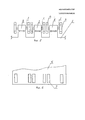
Фиг.8, фиг.9, фиг.10, фиг.11 - рекомендуемые формы лопастей.Fig.8, Fig.9, Fig.10, Fig.11 - the recommended shape of the blades.
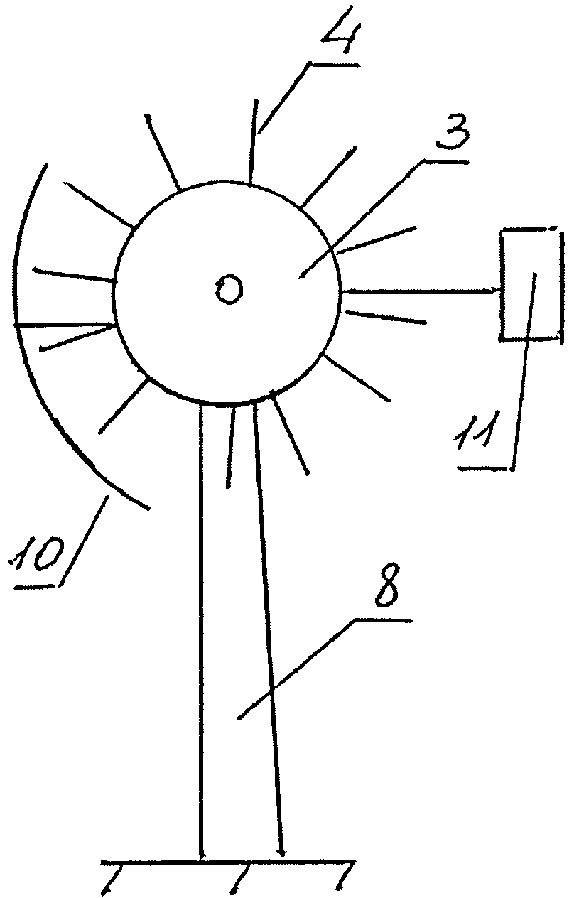
Фиг.12 - установка генератора на стационарном ветрогенераторе (ветряке) (вид спереди),Fig - installation of a generator on a stationary wind generator (windmill) (front view),
где 1 - вал генератора;where 1 is the generator shaft;
2 - генератор;2 - generator;
4 - лопасти;4 - blades;
8 - стойка ветряка;8 - stand of the windmill;
9 - подшипник;9 - bearing;
10 - защита;10 - protection;
11 - пластина (принцип флюгера);11 - plate (wind vane principle);
12 - плита для крепежа генератора и защиты.12 - plate for mounting the generator and protection.
Фиг.13 - установка генератора на стационарном ветрогенераторе (ветряке) (вид сбоку), где 3 - шкив;Fig - installation of a generator on a stationary wind generator (windmill) (side view), where 3 is a pulley;
4 - лопасти;4 - blades;
8 - стойка ветряка;8 - stand of the windmill;
10 - защита;10 - protection;
11 - пластина (принцип флюгера).11 - plate (weather vane principle).
Пример осуществления.An example implementation.
Чтобы использовать встречный поток воздуха, на вал генератора одевают шкив с лопастями, изготовленными из пластмассы, алюминия, титана и т.д. Для увеличения производительности и скорости вращения в заводских условиях удлиняют вал генератора, на вал генератора надевают второй шкив с лопастями (фиг.1, фиг.2, фиг.3, фиг.4). Модернизированные генераторы устанавливают перпендикулярно потоку воздуха, как на электромобилях, так и на стационарных ветрогенераторах (ветряках). Крепежная рейка жестко (например, болтами) крепится к корпусу электромобиля ниже уровня крыши корпуса электромобиля, при этом крыша корпуса электромобиля имеет прорези в виде прямоугольных отверстий для свободного выхода лопастей (фиг.6). Для увеличения мощности на одной крепежной рейке могут быть установлены несколько генераторов, каждый жестко (например, болтами) монтируется к крепежной рейке, при этом каждый генератор содержит удлиненный вал, на каждом из которых с двух сторон от генератора установлен шкив с лопастями. Количество прорезей в виде прямоугольных отверстий в крыше корпуса электромобиля соответствует количеству шкивов, установленных на валу ротора, количество шкивов соответствует как минимум два на каждый генератор, количество генераторов зависит от требуемой мощности, каждый генератор установлен перпендикулярно потоку воздуха. При необходимости более высокой мощности зарядки аккумуляторов, возможна установка дополнительной крепежной рейки во второй ряд, при этом генераторы устанавливаются таким образом, чтобы шкивы с лопастями второго ряда не совпадали с расположением шкивов второго ряда при фронтальной проекции (вид спереди, вид сзади), прорези в корпусе крыши выполнены в шахматном порядке и позволяют использовать воздушный поток, не заслоняемый лопастями шкивов первого ряда.To use a counter flow of air, a pulley with blades made of plastic, aluminum, titanium, etc., is put on the generator shaft. To increase productivity and rotation speed in the factory, the generator shaft is extended, a second pulley with blades is put on the generator shaft (Fig. 1, Fig. 2, Fig. 3, Fig. 4). Upgraded generators are installed perpendicular to the air flow, both on electric vehicles and on stationary wind generators (windmills). The mounting rail is rigidly (for example, bolted) attached to the body of the electric vehicle below the level of the roof of the body of the electric car, while the roof of the body of the electric car has slots in the form of rectangular holes for free exit of the blades (Fig.6). To increase power, several generators can be installed on one mounting rail, each is rigidly mounted (for example, with bolts) to the mounting rail, and each generator contains an elongated shaft, on each of which a pulley with blades is installed on both sides of the generator. The number of slots in the form of rectangular holes in the roof of the electric vehicle body corresponds to the number of pulleys mounted on the rotor shaft, the number of pulleys corresponds to at least two for each generator, the number of generators depends on the required power, each generator is installed perpendicular to the air flow. If you need a higher battery charging power, you can install an additional mounting rail in the second row, while the generators are installed so that the pulleys with the blades of the second row do not coincide with the location of the pulleys of the second row in front view (front view, rear view), slots in the roof casing is staggered and allows the use of an air stream not obscured by the blades of the pulleys of the first row.
Для примера возьмем вариант установки генератора на крышу электромобиля (фиг.5, фиг.6, фиг.7). для зарядки можно использовать один, два или несколько генераторов в зависимости от мощности аккумуляторных батарей. Крепежную рейку (фиг.5) изготавливают из металлопроката (например, шинки металлической, уголка и т.д.)For example, take the option of installing a generator on the roof of an electric vehicle (Fig. 5, Fig. 6, Fig. 7). For charging, you can use one, two or more generators, depending on the power of the batteries. The mounting rail (figure 5) is made of rolled metal (for example, a metal bar, corner, etc.)
Встречным потоком воздуха за счет движения лопастей ротор генератора начнет вращаться и вырабатывать электрический ток. При этом лопасти должны выходить за корпус электромобиля примерно на одну треть, а две трети должны быть закрыты (фиг.7). Чем больше высота и ширина лопастей, тем легче вращение лопастей генераторов. Рекомендуемые формы лопастей - фиг.8, фиг.9, фиг.10, фиг.11.The counter-flow of air due to the movement of the blades of the generator rotor will begin to rotate and generate an electric current. In this case, the blades should extend beyond the body of the electric vehicle by about one third, and two thirds should be closed (Fig. 7). The greater the height and width of the blades, the easier the rotation of the blades of the generators. Recommended shape of the blades - Fig.8, Fig.9, Fig.10, Fig.11.
Заявляемую полезную модель можно осуществить с изменением конструкции генератора (фиг.1, фиг.2), изготовления шкивов с прямыми лопастями (фиг.3, фиг.4, фиг.8, фиг.9, фиг.10, фиг.11), изготовления крепежной рейки для электромобиля и установкой генераторов с лопастными шкивами на электромобиле. Для изготовления ветрогенератора (фиг.12, фиг.13) сложностей нет.The inventive utility model can be implemented with a change in the design of the generator (figure 1, figure 2), the manufacture of pulleys with straight blades (figure 3, figure 4, figure 8, figure 9, figure 10, figure 11), manufacturing a mounting rail for an electric vehicle and installing generators with vane pulleys on an electric vehicle. For the manufacture of a wind generator (Fig, Fig, 13) there are no difficulties.
Заявляемая полезная модель позволяет существенно упростить конструкцию ветрогенератора электромобиля и повысить производительность использования встречного потока воздуха и силы ветра для подзарядки аккумуляторных батарей на электромобилях и выработки электроэнергии на ветрогенераторах, при помощи лопастных генераторов, устанавливаемых перпендикулярно потоку воздуха с прямыми лопастями, путем изменения конструкции генератора и горизонтального расположения вала генератора.The inventive utility model can significantly simplify the design of the wind generator of an electric vehicle and increase the productivity of using oncoming air flow and wind power to recharge batteries on electric vehicles and generate electricity on wind generators using vane generators installed perpendicular to the air flow with straight blades, by changing the design of the generator and horizontal location of the generator shaft.
Claims (4)
Priority Applications (1)
| Application Number | Priority Date | Filing Date | Title |
|---|---|---|---|
| RU2013100737/11U RU129052U1 (en) | 2013-01-09 | 2013-01-09 | ELECTRIC CAR WIND GENERATOR |
Applications Claiming Priority (1)
| Application Number | Priority Date | Filing Date | Title |
|---|---|---|---|
| RU2013100737/11U RU129052U1 (en) | 2013-01-09 | 2013-01-09 | ELECTRIC CAR WIND GENERATOR |
Publications (1)
| Publication Number | Publication Date |
|---|---|
| RU129052U1 true RU129052U1 (en) | 2013-06-20 |
Family
ID=48786886
Family Applications (1)
| Application Number | Title | Priority Date | Filing Date |
|---|---|---|---|
| RU2013100737/11U RU129052U1 (en) | 2013-01-09 | 2013-01-09 | ELECTRIC CAR WIND GENERATOR |
Country Status (1)
| Country | Link |
|---|---|
| RU (1) | RU129052U1 (en) |
Cited By (2)
| Publication number | Priority date | Publication date | Assignee | Title |
|---|---|---|---|---|
| RU2584054C2 (en) * | 2014-08-04 | 2016-05-20 | Петр Антипович Прохоров | Wind generator |
| RU2700802C1 (en) * | 2018-06-08 | 2019-09-23 | Александр Иванович Лобовиков | Double-sided wind generator |
-
2013
- 2013-01-09 RU RU2013100737/11U patent/RU129052U1/en not_active IP Right Cessation
Cited By (2)
| Publication number | Priority date | Publication date | Assignee | Title |
|---|---|---|---|---|
| RU2584054C2 (en) * | 2014-08-04 | 2016-05-20 | Петр Антипович Прохоров | Wind generator |
| RU2700802C1 (en) * | 2018-06-08 | 2019-09-23 | Александр Иванович Лобовиков | Double-sided wind generator |
Similar Documents
| Publication | Publication Date | Title |
|---|---|---|
| US20110037261A1 (en) | System And Method For Producing Electrical Power | |
| US6590363B2 (en) | Charging station | |
| US8362636B2 (en) | Portable 350 airpower module | |
| KR101502737B1 (en) | Power generating system using wasting energy from moving objects | |
| US9446670B1 (en) | Energy generating system | |
| JPH0715803A (en) | Wind-power charging equipment | |
| US20120085587A1 (en) | Wind Power for Electric Cars | |
| RU129052U1 (en) | ELECTRIC CAR WIND GENERATOR | |
| JP2010209786A (en) | On-vehicle wind turbine generator | |
| JP2017149168A (en) | Hybrid vehicle | |
| RU2700802C1 (en) | Double-sided wind generator | |
| KR101142460B1 (en) | Windpower generation apparatus for the vehicle | |
| WO2016006519A1 (en) | Hybrid vehicle | |
| CN210599277U (en) | Vehicle-mounted charging pile | |
| AU2014301698B2 (en) | Wind turbine for electric vehicle | |
| CA2808605C (en) | Fluid driven generator | |
| CN102785577A (en) | Electric automobile system driven by wind power generation | |
| JP3220741U (en) | Power generator using wind energy | |
| CN211830313U (en) | Movable wind power charging device | |
| CN204805032U (en) | Road antiglare equipment | |
| KR101650252B1 (en) | The Horizontal and Vertical Axis Wind Generator | |
| CN203717233U (en) | Wind wheel structure of vehicle-mounted wind power generation device | |
| JP5584741B2 (en) | Wind power generator | |
| CN203995732U (en) | A kind of wind power generation electronlmobil | |
| RU2704384C1 (en) | Locomotive wind generator |
Legal Events
| Date | Code | Title | Description |
|---|---|---|---|
| MM9K | Utility model has become invalid (non-payment of fees) |
Effective date: 20190110 |